2013 BMW 650I XDRIVE GRAN COUPE lights
[x] Cancel search: lightsPage 132 of 232
The Top View and PDC images are displayed if
the system is switched on via iDrive.
Automatic deactivation during forward
travel
The system switches off when a certain driving
distance or speed is exceeded.
Switch the system back on if necessary.
Switching on/off manually Press the button.▷On: the LED lights up.▷Off: the LED goes out.
Top View is displayed, switch on the backup
camera via the iDrive, refer to page 132.
Switching on the backup camera via the
iDrive
With Top View switched on:
"Rear view camera"
The backup camera image is displayed. The set‐
ting is stored for the remote control currently in
use.
Display
Visual warning
The approach of the vehicle to an object can be
shown on the Control Display.
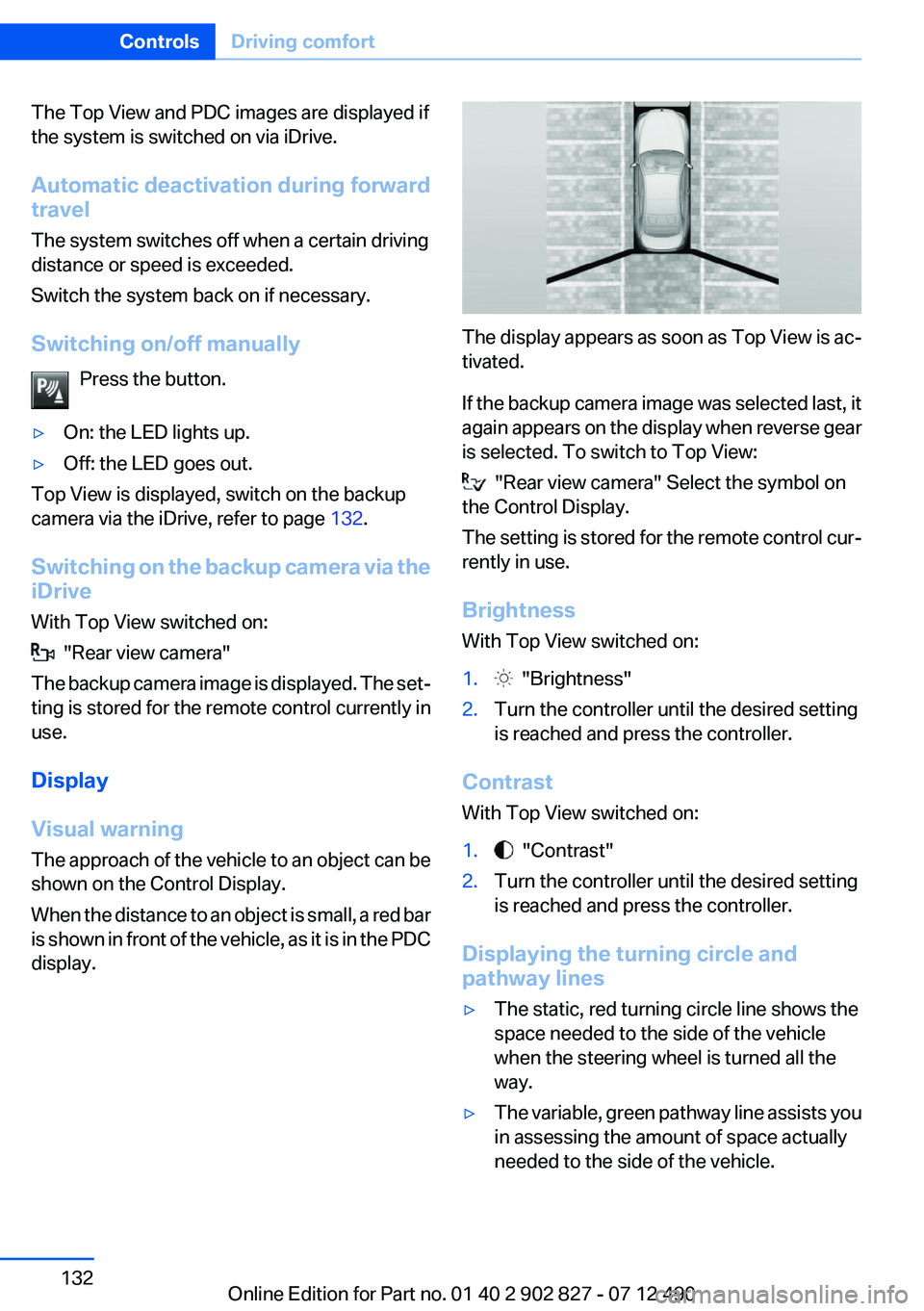
When the distance to an object is small, a red bar
is shown in front of the vehicle, as it is in the PDC
display.
The display appears as soon as Top View is ac‐
tivated.
If the backup camera image was selected last, it
again appears on the display when reverse gear
is selected. To switch to Top View:
"Rear view camera" Select the symbol on
the Control Display.
The setting is stored for the remote control cur‐
rently in use.
Brightness
With Top View switched on:
1. "Brightness"2.Turn the controller until the desired setting
is reached and press the controller.
Contrast
With Top View switched on:
1. "Contrast"2.Turn the controller until the desired setting
is reached and press the controller.
Displaying the turning circle and
pathway lines
▷The static, red turning circle line shows the
space needed to the side of the vehicle
when the steering wheel is turned all the
way.▷The variable, green pathway line assists you
in assessing the amount of space actually
needed to the side of the vehicle.Seite 132ControlsDriving comfort132
Online Edition for Part no. 01 40 2 902 827 - 07 12 490
Page 135 of 232
Therefore, always be alert and ready to inter‐
vene; otherwise, there is the danger of an acci‐
dent occurring.◀
Curbs
The parking assistant may steer the vehi‐
cle over or onto curbs.
Therefore, always be alert and ready to inter‐
vene; otherwise, the wheels, tires, or the vehicle
may become damaged.◀
An engine that has been switched off by the
Auto Start Stop function is restarted automati‐
cally when the parking assistant is activated.
Requirements
For measuring parking spaces▷Maximum speed while driving forward ap‐
prox. 22 mph/35 km/h.▷Maximum distance to row of parked vehi‐
cles: 5 ft/1.5 m.▷When parking in parking spaces on the driv‐
er's side, the corresponding turn signal must
be set.
Suitable parking space
▷Gap between two objects with a minimum
length of approx. 5 ft/1.5 m.▷Minimum length of the gap: own vehicle's
length plus approx 4 ft/1.2 m.▷Minimum depth: approx. 5 ft/1.5 m.
For parking procedure
Closed doors.
At a glance
Button in the vehicle
Parking assistant
Ultrasound sensors
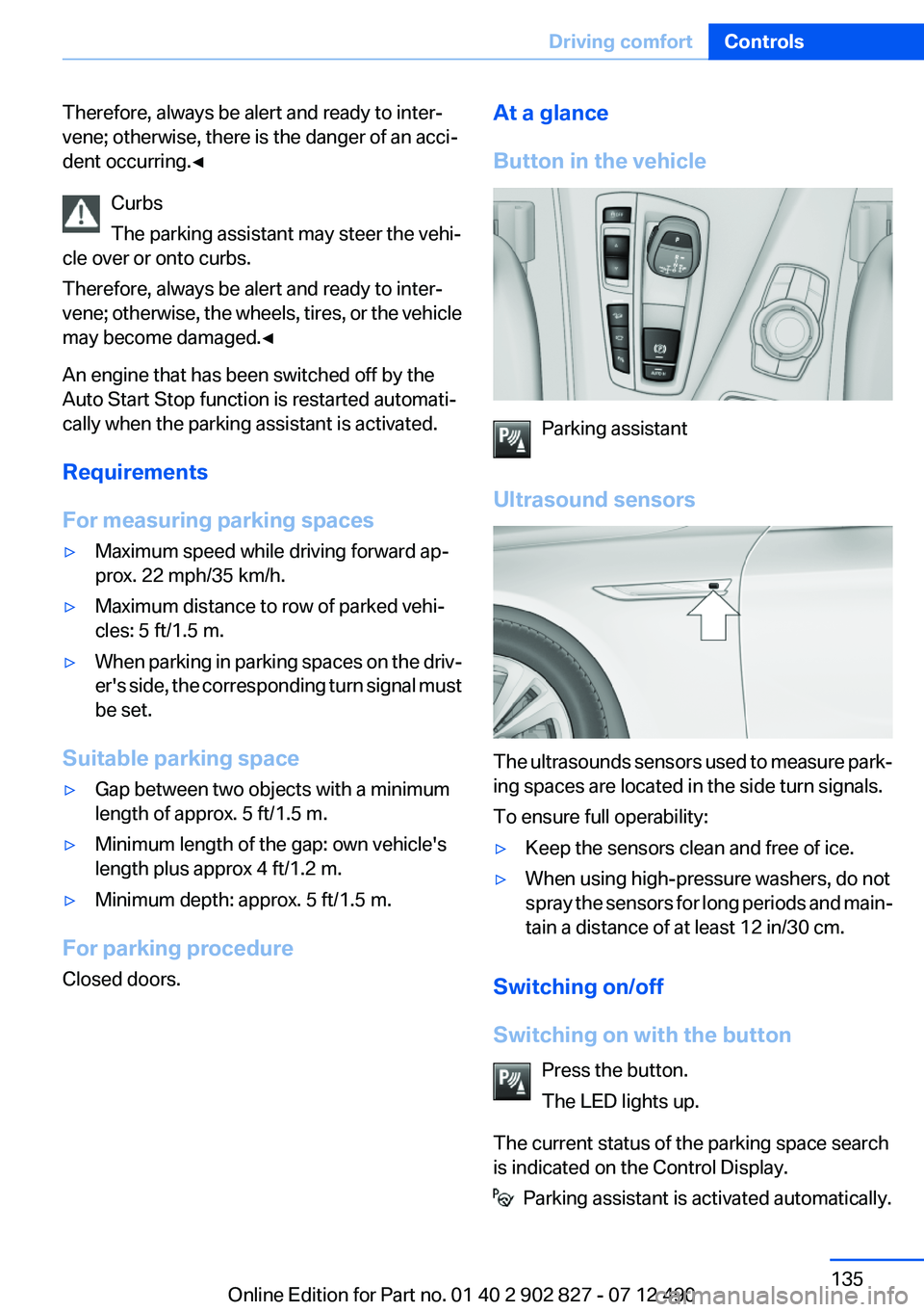
The ultrasounds sensors used to measure park‐
ing spaces are located in the side turn signals.
To ensure full operability:
▷Keep the sensors clean and free of ice.▷When using high-pressure washers, do not
spray the sensors for long periods and main‐
tain a distance of at least 12 in/30 cm.
Switching on/off
Switching on with the button Press the button.
The LED lights up.
The current status of the parking space search
is indicated on the Control Display.
Parking assistant is activated automatically.
Seite 135Driving comfortControls135
Online Edition for Part no. 01 40 2 902 827 - 07 12 490
Page 144 of 232
Toward red: warmer.▷Lever for changing the air flow direction, ar‐
row 2.▷Thumbwheels for continuous opening and
closing of the vents, arrow 3.
Parked-car ventilation
The concept
The parked-car ventilation ventilates the vehicle
interior and lowers its temperature, if necessary.
The system can be switched on and off directly
or by using two preset switch-on times. It re‐
mains switched on for 30 minutes.
Operation can be performed via iDrive.
Parked-car ventilation
Using the preset switch-on time or when oper‐
ated directly: any external temperature.
Open the vents to allow air to flow out.
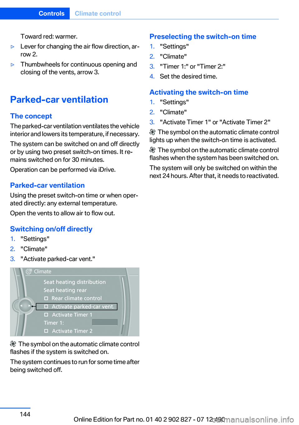
Switching on/off directly
1."Settings"2."Climate"3."Activate parked-car vent."
The symbol on the automatic climate control
flashes if the system is switched on.
The system continues to run for some time after
being switched off.
Preselecting the switch-on time1."Settings"2."Climate"3."Timer 1:" or "Timer 2:"4.Set the desired time.
Activating the switch-on time
1."Settings"2."Climate"3."Activate Timer 1" or "Activate Timer 2"
The symbol on the automatic climate control
lights up when the switch-on time is activated.
The symbol on the automatic climate control
flashes when the system has been switched on.
The system will only be switched on within the
next 24 hours. After that, it needs to reactivated.
Seite 144ControlsClimate control144
Online Edition for Part no. 01 40 2 902 827 - 07 12 490
Page 164 of 232
Switch off the engine during
longer stops
Switch off the engine during longer stops, e.g.,
at traffic lights, railroad crossings or in traffic
congestion.
Auto Start/Stop function
The Auto Start/Stop function of your vehicle au‐
tomatically switches off the engine during a
stop.
If the engine is switched off and then restarted
rather than leaving the engine running con‐
stantly, fuel consumption and emissions are re‐
duced. Savings can begin within a few seconds
of switching off the engine.
Using this system can cause certain compo‐
nents of the vehicle to become worn prema‐
turely.
Iin addition, fuel consumption is also determined
by other factors, such as driving style, road con‐
ditions, maintenance or environmental factors.
Switch off any functions that
are not currently needed
Functions such as seat heating and the rear win‐
dow defroster require a lot of energy and con‐
sume additional fuel, especially in city and stop-
and-go traffic.
Therefore, switch off these functions if they are
not actually needed.
Have maintenance carried out
Have vehicles maintained regularly to achieve
optimal vehicle economy and operating life.
Have the maintenance carried out by your serv‐
ice center.
Please also note the BMW Maintenance Sys‐
tem, refer to page 189.ECO PRO
The concept
ECO PRO supports a driving style that saves on
fuel consumption. For this purpose, the engine
control and comfort functions, e. g. the climate
control output, are adjusted.
The extension of the range that is achieved as a
result can be displayed in the instrument cluster.
Activating ECO PRO Press button repeatedly until ECO PRO
is displayed in the instrument cluster.
Display in the instrument cluster
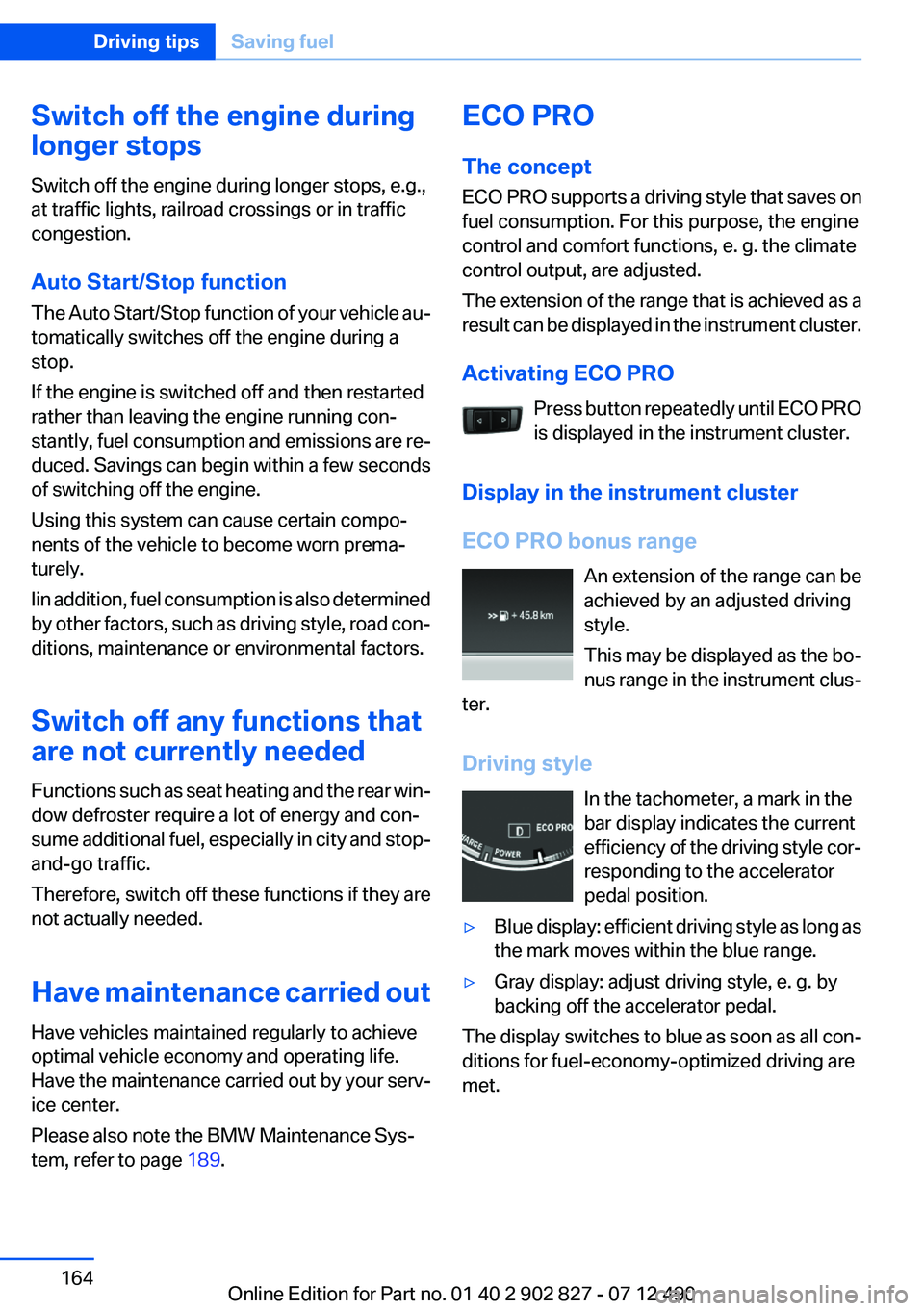
ECO PRO bonus range An extension of the range can be
achieved by an adjusted driving
style.
This may be displayed as the bo‐
nus range in the instrument clus‐
ter.
Driving style In the tachometer, a mark in the
bar display indicates the current
efficiency of the driving style cor‐
responding to the accelerator
pedal position.▷Blue display: efficient driving style as long as
the mark moves within the blue range.▷Gray display: adjust driving style, e. g. by
backing off the accelerator pedal.
The display switches to blue as soon as all con‐
ditions for fuel-economy-optimized driving are
met.
Seite 164Driving tipsSaving fuel164
Online Edition for Part no. 01 40 2 902 827 - 07 12 490
Page 187 of 232
3. "Measure engine oil level"4."Start measurement"
The oil level is checked and displayed via a scale.
Duration: approx. 1 minute.
Adding engine oil
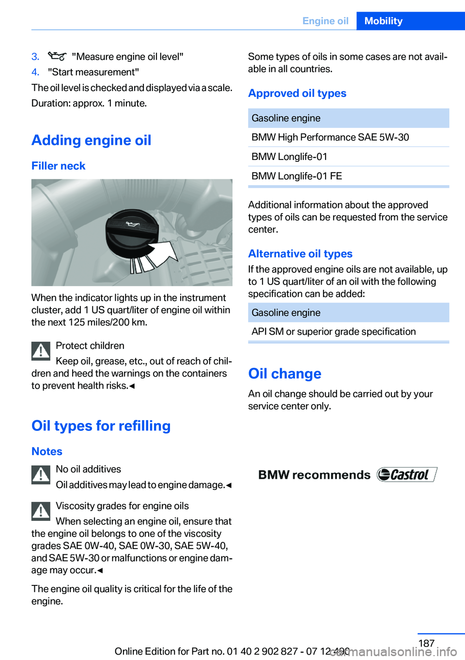
Filler neck
When the indicator lights up in the instrument
cluster, add 1 US quart/liter of engine oil within
the next 125 miles/200 km.
Protect children
Keep oil, grease, etc., out of reach of chil‐
dren and heed the warnings on the containers
to prevent health risks.◀
Oil types for refilling
Notes No oil additives
Oil additives may lead to engine damage. ◀
Viscosity grades for engine oils
When selecting an engine oil, ensure that
the engine oil belongs to one of the viscosity
grades SAE 0W-40, SAE 0W-30, SAE 5W-40,
and SAE 5W-30 or malfunctions or engine dam‐
age may occur.◀
The engine oil quality is critical for the life of the
engine.
Some types of oils in some cases are not avail‐
able in all countries.
Approved oil typesGasoline engineBMW High Performance SAE 5W-30BMW Longlife-01BMW Longlife-01 FE
Additional information about the approved
types of oils can be requested from the service
center.
Alternative oil types
If the approved engine oils are not available, up
to 1 US quart/liter of an oil with the following
specification can be added:
Gasoline engineAPI SM or superior grade specification
Oil change
An oil change should be carried out by your
service center only.
Seite 187Engine oilMobility187
Online Edition for Part no. 01 40 2 902 827 - 07 12 490
Page 190 of 232
Socket for OBD Onboard
Diagnosis
Position
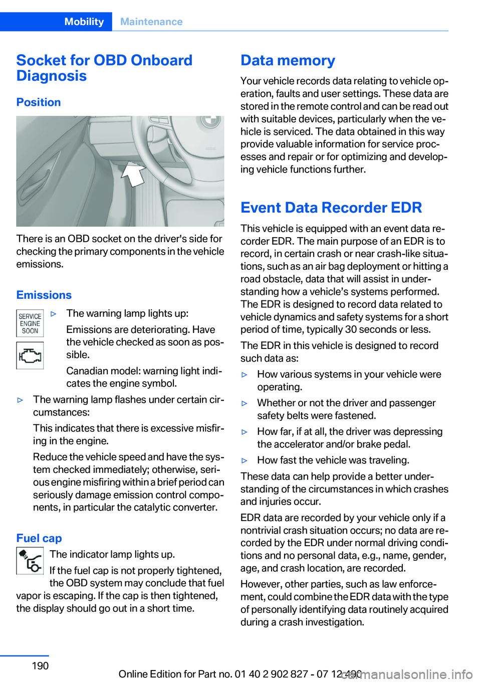
There is an OBD socket on the driver's side for
checking the primary components in the vehicle
emissions.
Emissions
▷The warning lamp lights up:
Emissions are deteriorating. Have
the vehicle checked as soon as pos‐
sible.
Canadian model: warning light indi‐
cates the engine symbol.▷The warning lamp flashes under certain cir‐
cumstances:
This indicates that there is excessive misfir‐
ing in the engine.
Reduce the vehicle speed and have the sys‐
tem checked immediately; otherwise, seri‐
ous engine misfiring within a brief period can
seriously damage emission control compo‐
nents, in particular the catalytic converter.
Fuel cap
The indicator lamp lights up.
If the fuel cap is not properly tightened,
the OBD system may conclude that fuel
vapor is escaping. If the cap is then tightened,
the display should go out in a short time.
Data memory
Your vehicle records data relating to vehicle op‐
eration, faults and user settings. These data are
stored in the remote control and can be read out
with suitable devices, particularly when the ve‐
hicle is serviced. The data obtained in this way
provide valuable information for service proc‐
esses and repair or for optimizing and develop‐
ing vehicle functions further.
Event Data Recorder EDR
This vehicle is equipped with an event data re‐
corder EDR. The main purpose of an EDR is to
record, in certain crash or near crash-like situa‐
tions, such as an air bag deployment or hitting a
road obstacle, data that will assist in under‐
standing how a vehicle’s systems performed.
The EDR is designed to record data related to
vehicle dynamics and safety systems for a short
period of time, typically 30 seconds or less.
The EDR in this vehicle is designed to record
such data as:▷How various systems in your vehicle were
operating.▷Whether or not the driver and passenger
safety belts were fastened.▷How far, if at all, the driver was depressing
the accelerator and/or brake pedal.▷How fast the vehicle was traveling.
These data can help provide a better under‐
standing of the circumstances in which crashes
and injuries occur.
EDR data are recorded by your vehicle only if a
nontrivial crash situation occurs; no data are re‐
corded by the EDR under normal driving condi‐
tions and no personal data, e.g., name, gender,
age, and crash location, are recorded.
However, other parties, such as law enforce‐
ment, could combine the EDR data with the type
of personally identifying data routinely acquired
during a crash investigation.
Seite 190MobilityMaintenance190
Online Edition for Part no. 01 40 2 902 827 - 07 12 490
Page 193 of 232
Danger of burns
Only change bulbs when they are cool;
otherwise, there is the danger of getting
burned.◀
Working on the lighting system
When working on the lighting system, you
should always switch off the lights affected to
prevent short circuits.
To avoid possible injury or equipment damage
when replacing bulbs, observe any instructions
provided by the bulb manufacturer.◀
Do not perform work/bulb replacement on
xenon headlamps
Have any work on the xenon lighting system, in‐
cluding bulb replacement, performed only by a
service center. Due to the high voltage present
in the system, there is the danger of fatal injuries
if work is carried out improperly.◀
Do not touch the bulbs
Do not touch the glass of new bulbs with
your bare hands, as even minute amounts of
contamination will burn into the bulb's surface
and reduce its service life.
Use a clean tissue, cloth or something similar, or
hold the bulb by its base.◀
Light-emitting diodes (LEDs)
Light-emitting diodes installed behind a cover
serve as the light source for controls, display el‐
ements and other equipment.
These light-emitting diodes, which are related
to conventional lasers, are officially designated
as Class 1 light-emitting diodes.
Do not remove the covers
Do not remove the covers, and never stare
into the unfiltered light for several hours; other‐
wise, irritation of the retina could result.◀Headlamp glass
Condensation can form on the inside of the ex‐
ternal lamps in cool or humid weather. When
driving with the light switched on, the conden‐
sation evaporates after a short time. The head‐
lamp glasses do not need to be changed.
If the headlamps do not dim despite driving with
the light switched on, increasing humidity forms,
e. g. water droplets in the light, have the service
center check this.
Xenon headlamps
Notes
Because of the long life of these bulbs, the like‐
lihood of failure is very low. Switching the lamps
on and off frequently shortens their life.
If a xenon bulb fails, switch on the front fog lamps
and continue the trip with great care. Comply
with local regulations.
Do not perform work/bulb replacement on
xenon headlamps
Have any work on the xenon lighting system, in‐
cluding bulb replacement, performed only by a
service center. Due to the high voltage present
in the system, there is the danger of fatal injuries
if work is carried out improperly.◀
For checking and adjusting headlamp aim,
please contact your BMW center.
Light-emitting diodes (LEDs)
Follow the general instructions on lamps and
bulbs, refer to page 192.
With Xenon-headlamps, the following lamps are
designed with LED technology:▷Parking lamps and roadside parking lamps▷Turn signals, incl. side indicators▷Front fog lamps▷Daytime running lights
Contact your service center in the event of a
malfunction.
Seite 193Replacing componentsMobility193
Online Edition for Part no. 01 40 2 902 827 - 07 12 490
Page 194 of 232
Turning lamp on the Xenon headlamp
Follow the general instructions on lamps and
bulbs, refer to page 192.
The illustration shows the left side of the engine
compartment.
55-watt bulb, H31.Turn the cap and remove it.2.Detach the wire bracket.3.Disconnect the cable at the plug-in connec‐
tion and remove the bulb.4.Insert the new bulb. Ensure that the bulb has
the correct orientation. Because of its
shape, the bulb can only be inserted in one
direction.5.Secure the bulb with the wire bracket.6.Connect the bulb.7.Mount the cap.
LED headlamps
Light-emitting diodes (LEDs)
Follow the general instructions on lamps and
bulbs, refer to page 192.
With LED headlamps, all front lamps and side
indicators are designed with LED technology.
If and LED fails, switch on the front fog lamps
and continue the trip with great care. Comply
with local regulations.
Contact your service center in the event of a
malfunction.
Tail lamps, bulb replacement
At a glance1Turn signal/brake lamp2Reversing lamp3Inside brake lamp4Tail lamp5Outside brake lamp6Rear reflector
Turn signal, outer brake, tail, and
license plate lamps
Follow the general instructions on lamps and
bulbs, refer to page 192.
These lights feature LED technology.
Contact your service center in the event of a
malfunction.
Seite 194MobilityReplacing components194
Online Edition for Part no. 01 40 2 902 827 - 07 12 490