2013 BMW 650I XDRIVE CONVERTIBLE check engine
[x] Cancel search: check enginePage 195 of 240
MaintenanceVehicle equipment
All standard, country-specific and optional
equipment that is offered in the model series is
described in this chapter. Therefore, equipment
is also described that is not available in a vehicle,
e. g., because of the selected optional equip‐
ment or country variant. This also applies for
safety-related functions and systems.
BMW Maintenance System
The maintenance system directs you to re‐
quired maintenance measures and thereby sup‐
ports you in maintaining road safety and the op‐
erational reliability of the vehicle.
Condition Based Service CBS
Sensors and special algorithms take into ac‐
count the driving conditions of your vehicle.
Based on this, Condition Based Service deter‐
mines the maintenance requirements.
The system makes it possible to adapt the
amount of maintenance you need to your user
profile.
Details on the service requirements, refer to
page 84, can be displayed on the Control Dis‐
play.
Service data in the remote control
Information on the required maintenance is con‐
tinuously stored in the remote control. Your
service center will read out this data and suggest
the right array of service procedures for your ve‐
hicle.
Therefore, hand your service specialist the re‐
mote control that you used most recently.Storage periods
Storage periods during which the vehicle bat‐
tery was disconnected are not taken into ac‐
count.
If this occurs, have a service center update the
time-dependent maintenance procedures,
such as checking brake fluid and, if necessary,
changing the engine oil and the microfilter/acti‐
vated-charcoal filter.
Service and Warranty
Information Booklet for US
models and Warranty and
Service Guide Booklet for
Canadian models
Please consult your Service and Warranty Infor‐
mation Booklet for US models and Warranty and
Service Guide Booklet for Canadian models for
additional information on service requirements.
Maintenance and repair should be performed by
your service center. Make sure to have regular
maintenance procedures recorded in the vehi‐
cle's Service and Warranty Information Booklet
for US models, and in the Warranty and Service
Guide Booklet for Canadian models. These en‐
tries are proof of regular maintenance.Seite 195MaintenanceMobility195
Online Edition for Part no. 01 40 2 903 169 - 07 12 490
Page 196 of 240
Socket for OBD Onboard
Diagnosis
Position
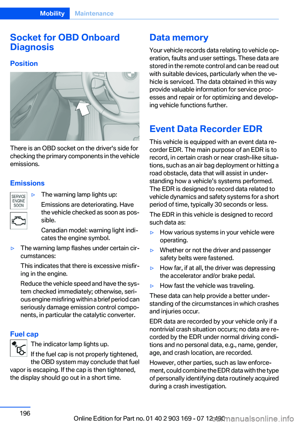
There is an OBD socket on the driver's side for
checking the primary components in the vehicle
emissions.
Emissions
▷The warning lamp lights up:
Emissions are deteriorating. Have
the vehicle checked as soon as pos‐
sible.
Canadian model: warning light indi‐
cates the engine symbol.▷The warning lamp flashes under certain cir‐
cumstances:
This indicates that there is excessive misfir‐
ing in the engine.
Reduce the vehicle speed and have the sys‐
tem checked immediately; otherwise, seri‐
ous engine misfiring within a brief period can
seriously damage emission control compo‐
nents, in particular the catalytic converter.
Fuel cap
The indicator lamp lights up.
If the fuel cap is not properly tightened,
the OBD system may conclude that fuel
vapor is escaping. If the cap is then tightened,
the display should go out in a short time.
Data memory
Your vehicle records data relating to vehicle op‐
eration, faults and user settings. These data are
stored in the remote control and can be read out
with suitable devices, particularly when the ve‐
hicle is serviced. The data obtained in this way
provide valuable information for service proc‐
esses and repair or for optimizing and develop‐
ing vehicle functions further.
Event Data Recorder EDR
This vehicle is equipped with an event data re‐
corder EDR. The main purpose of an EDR is to
record, in certain crash or near crash-like situa‐
tions, such as an air bag deployment or hitting a
road obstacle, data that will assist in under‐
standing how a vehicle’s systems performed.
The EDR is designed to record data related to
vehicle dynamics and safety systems for a short
period of time, typically 30 seconds or less.
The EDR in this vehicle is designed to record
such data as:▷How various systems in your vehicle were
operating.▷Whether or not the driver and passenger
safety belts were fastened.▷How far, if at all, the driver was depressing
the accelerator and/or brake pedal.▷How fast the vehicle was traveling.
These data can help provide a better under‐
standing of the circumstances in which crashes
and injuries occur.
EDR data are recorded by your vehicle only if a
nontrivial crash situation occurs; no data are re‐
corded by the EDR under normal driving condi‐
tions and no personal data, e.g., name, gender,
age, and crash location, are recorded.
However, other parties, such as law enforce‐
ment, could combine the EDR data with the type
of personally identifying data routinely acquired
during a crash investigation.
Seite 196MobilityMaintenance196
Online Edition for Part no. 01 40 2 903 169 - 07 12 490
Page 202 of 240
Lug bolt lock
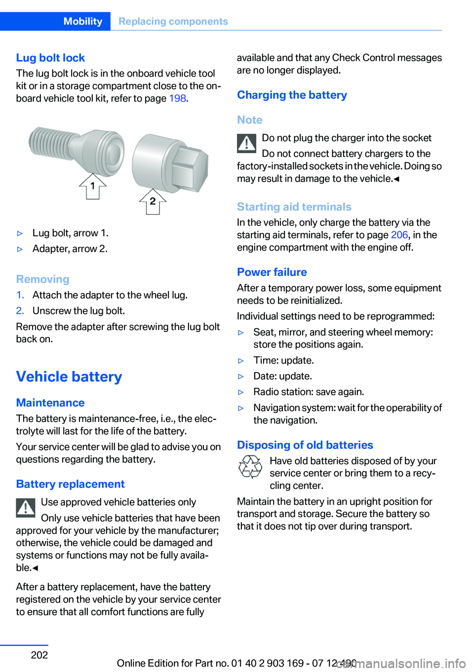
The lug bolt lock is in the onboard vehicle tool
kit or in a storage compartment close to the on‐
board vehicle tool kit, refer to page 198.▷Lug bolt, arrow 1.▷Adapter, arrow 2.
Removing
1.Attach the adapter to the wheel lug.2.Unscrew the lug bolt.
Remove the adapter after screwing the lug bolt
back on.
Vehicle battery
Maintenance
The battery is maintenance-free, i.e., the elec‐
trolyte will last for the life of the battery.
Your service center will be glad to advise you on
questions regarding the battery.
Battery replacement Use approved vehicle batteries only
Only use vehicle batteries that have been
approved for your vehicle by the manufacturer;
otherwise, the vehicle could be damaged and
systems or functions may not be fully availa‐
ble.◀
After a battery replacement, have the battery
registered on the vehicle by your service center
to ensure that all comfort functions are fully
available and that any Check Control messages
are no longer displayed.
Charging the battery
Note Do not plug the charger into the socket
Do not connect battery chargers to the
factory-installed sockets in the vehicle. Doing so
may result in damage to the vehicle.◀
Starting aid terminals
In the vehicle, only charge the battery via the
starting aid terminals, refer to page 206, in the
engine compartment with the engine off.
Power failure
After a temporary power loss, some equipment
needs to be reinitialized.
Individual settings need to be reprogrammed:▷Seat, mirror, and steering wheel memory:
store the positions again.▷Time: update.▷Date: update.▷Radio station: save again.▷Navigation system: wait for the operability of
the navigation.
Disposing of old batteries
Have old batteries disposed of by your
service center or bring them to a recy‐
cling center.
Maintain the battery in an upright position for
transport and storage. Secure the battery so
that it does not tip over during transport.
Seite 202MobilityReplacing components202
Online Edition for Part no. 01 40 2 903 169 - 07 12 490
Page 206 of 240
Roadside Assistance
The Roadside Assistance phone number can be
viewed on the iDrive or a connection to Roadside
Assistance can be established directly. Phone,
see user's manual for Navigation, Entertainment
and Communication.
Jump-starting
Notes
If the battery is discharged, an engine can be
started using the battery of another vehicle and
two jumper cables. Only use jumper cables with
fully insulated clamp handles.
To prevent personal injury or damage to both
vehicles, adhere strictly to the following proce‐
dure.
Do not touch live parts
To avoid the risk of potentially fatal injury,
always avoid all contact with electrical compo‐
nents while the engine is running.◀
Preparation1.Check whether the battery of the other ve‐
hicle has a voltage of 12 volts. This informa‐
tion can be found on the battery.2.Switch off the engine of the assisting vehi‐
cle.3.Switch off any electronic systems/power
consumers in both vehicles.
Bodywork contact between vehicles
Make sure that there is no contact be‐
tween the bodywork of the two vehicles; other‐
wise, there is the danger of short circuits.◀
Starting aid terminals Connecting order
Connect the jumper cables in the correct
order; otherwise, there is the danger of injury
from sparking.◀
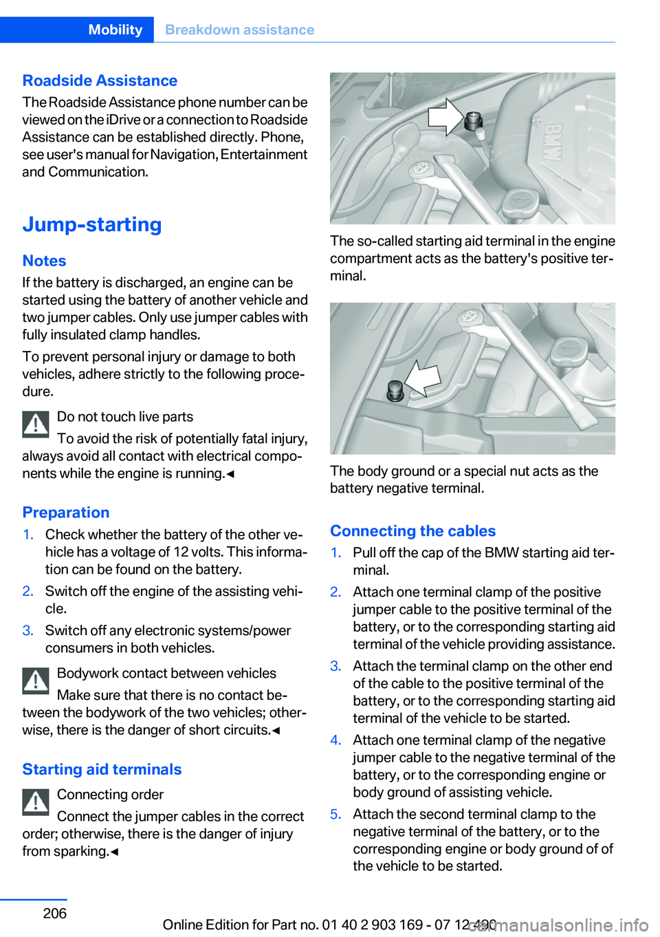
The so-called starting aid terminal in the engine
compartment acts as the battery's positive ter‐
minal.
The body ground or a special nut acts as the
battery negative terminal.
Connecting the cables
1.Pull off the cap of the BMW starting aid ter‐
minal.2.Attach one terminal clamp of the positive
jumper cable to the positive terminal of the
battery, or to the corresponding starting aid
terminal of the vehicle providing assistance.3.Attach the terminal clamp on the other end
of the cable to the positive terminal of the
battery, or to the corresponding starting aid
terminal of the vehicle to be started.4.Attach one terminal clamp of the negative
jumper cable to the negative terminal of the
battery, or to the corresponding engine or
body ground of assisting vehicle.5.Attach the second terminal clamp to the
negative terminal of the battery, or to the
corresponding engine or body ground of of
the vehicle to be started.Seite 206MobilityBreakdown assistance206
Online Edition for Part no. 01 40 2 903 169 - 07 12 490
Page 207 of 240
Starting the engine
Never use spray fluids to start the engine.1.Start the engine of the assisting vehicle and
let it run for several minutes at an increased
idle speed.2.Start the engine of the vehicle being started
in the usual way.
If the first starting attempt is not successful,
wait a few minutes before making another
attempt in order to allow the discharged bat‐
tery to recharge.3.Let both engines run for several minutes.4.Disconnect the jumper cables in the reverse
order.
Check the battery and recharge if necessary.
Tow-starting and towing
Manual transmission
Observe before towing your vehicle
Gearshift lever in neutral position.
Towing When the parking brake is blocked
The parking brake cannot be released
manually.
Do not tow the vehicle with the parking brake
blocked, or the vehicle can be damaged.
Contact your service center.◀
Follow the towing instructions
Follow all towing instructions; otherwise,
vehicle damage or accidents may occur.◀
▷Make sure that the ignition is switched on;
otherwise, the low beams, tail lamps, turn
signals, and windshield wipers may be un‐
available.▷Do not tow the vehicle with the rear axle
tilted, as the front wheels could turn.▷When the engine is stopped, there is no
power assist. Consequently, more force
needs to be applied when braking and steer‐
ing.▷Larger steering wheel movements are re‐
quired.▷The towing vehicle must not be lighter than
the vehicle being towed; otherwise, it will not
be possible to control the vehicle response.
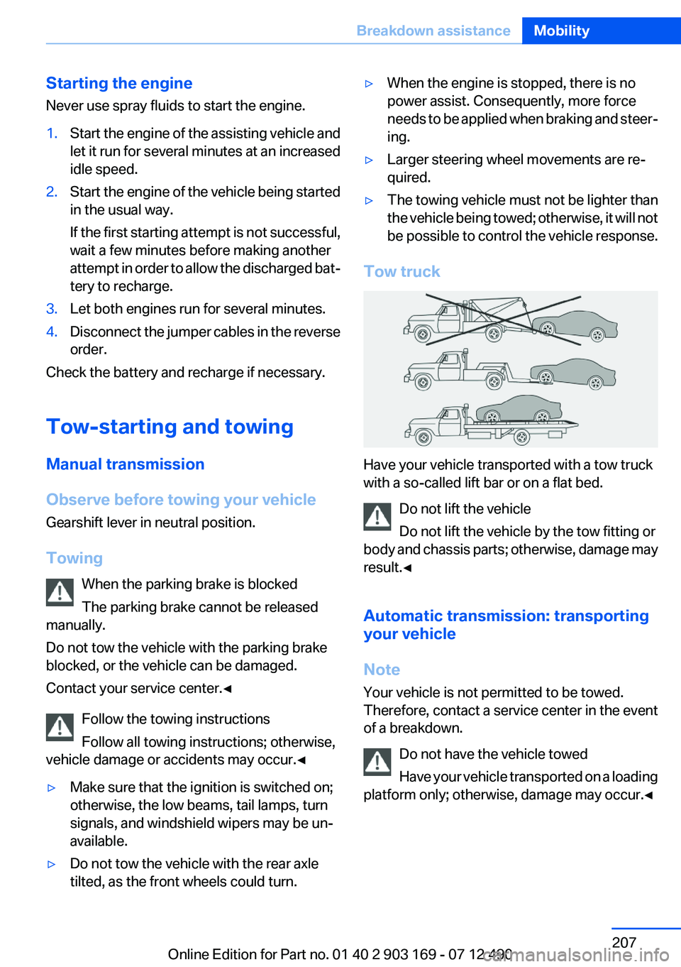
Tow truck
Have your vehicle transported with a tow truck
with a so-called lift bar or on a flat bed.
Do not lift the vehicle
Do not lift the vehicle by the tow fitting or
body and chassis parts; otherwise, damage may
result.◀
Automatic transmission: transporting
your vehicle
Note
Your vehicle is not permitted to be towed.
Therefore, contact a service center in the event
of a breakdown.
Do not have the vehicle towed
Have your vehicle transported on a loading
platform only; otherwise, damage may occur.◀
Seite 207Breakdown assistanceMobility207
Online Edition for Part no. 01 40 2 903 169 - 07 12 490
Page 209 of 240
▷Avoid lateral loading of the tow fitting, e.g.,
do not lift the vehicle by the tow fitting.
Otherwise, damage to the tow fitting and the ve‐
hicle can occur.◀
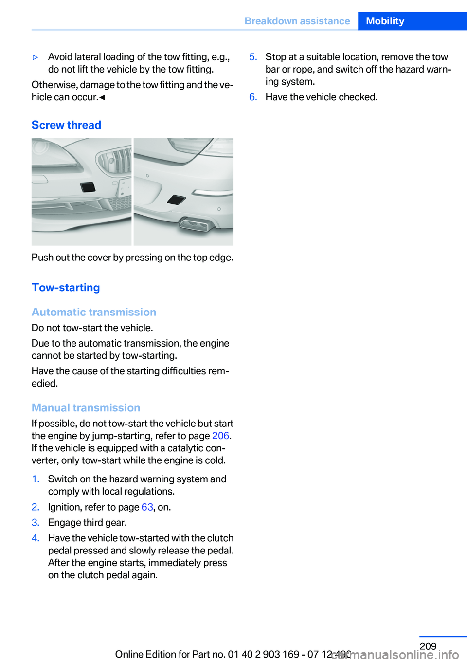
Screw thread
Push out the cover by pressing on the top edge.
Tow-starting
Automatic transmission
Do not tow-start the vehicle.
Due to the automatic transmission, the engine
cannot be started by tow-starting.
Have the cause of the starting difficulties rem‐
edied.
Manual transmission
If possible, do not tow-start the vehicle but start
the engine by jump-starting, refer to page 206.
If the vehicle is equipped with a catalytic con‐
verter, only tow-start while the engine is cold.
1.Switch on the hazard warning system and
comply with local regulations.2.Ignition, refer to page 63, on.3.Engage third gear.4.Have the vehicle tow-started with the clutch
pedal pressed and slowly release the pedal.
After the engine starts, immediately press
on the clutch pedal again.5.Stop at a suitable location, remove the tow
bar or rope, and switch off the hazard warn‐
ing system.6.Have the vehicle checked.Seite 209Breakdown assistanceMobility209
Online Edition for Part no. 01 40 2 903 169 - 07 12 490
Page 211 of 240
Manual transmission:1.Release the parking brake.2.Drive into the car wash.3.Shift to neutral.4.Switch the engine off.5.Switch on the ignition.
Automatic transmission:
1.Release parking brake, refer to page 67, and
deactivate Automatic Hold, refer to
page 68.2.Drive into the car wash.3.Depress the brake pedal as needed.4.Engage transmission position N.5.Switch the engine off. In this way, the igni‐
tion remains switched on, and a Check-Con‐
trol message is displayed.
Transmission position P with the igni‐
tion off
When the ignition is switched off, position P
is engaged automatically. When in an auto‐
matic car wash, for example, ensure that the
ignition is not switched off accidentally.◀
The vehicle cannot be locked from the outside
when in transmission position N. A signal is
sounded when an attempt is made to lock the
vehicle.
Transmission position
Transmission position P is engaged automati‐
cally:
▷When the ignition is switched off.▷After approx. 15 minutes.
Headlamps
▷Do not rub dry and do not use abrasive or
caustic cleansers.▷Soak areas that have been soiled e.g. due to
insects, with shampoo and wash off with
water.▷Thaw ice with deicing spray; do not use an
ice scraper.
After washing the vehicle
After washing the vehicle, apply the brakes
briefly to dry them; otherwise, braking action can
be reduced and corrosion of the brake discs can
occur.
Remove all residue completely from the wind‐
shields, otherwise streaking may cause loss of
visibility and wiper noise when the windshield
wipers are operated.
Vehicle care
Car care products
BMW recommends using cleaning and care
products from BMW, since these have been
tested and approved.
Car care and cleaning products
Follow the instructions on the container.
When cleaning the interior, open the doors or
windows.
Only use products intended for cleaning vehi‐
cles.
Cleansers can contain substances that are dan‐
gerous and harmful to your health.◀
Vehicle paint
Regular care contributes to driving safety and
value retention. Environmental influences in
areas with elevated air pollution or natural con‐
taminants, such as tree resin or pollen can affect
the vehicle's paintwork. Tailor the frequency
and extent of your car care to these influences.
Aggressive substances such as spilled fuel, oil,
grease or bird droppings must be removed im‐
mediately to prevent the finish from being al‐
tered or discolored.
Seite 211CareMobility211
Online Edition for Part no. 01 40 2 903 169 - 07 12 490
Page 233 of 240
Exterior mirror, automatic dim‐ming feature 58
Exterior mirrors 57
External start 206
External temperature dis‐ play 83
External temperature warn‐ ing 83
Eyes for securing cargo 168
F
Failure message, refer to Check Control 80
False alarm, refer to Uninten‐ tional alarm 42
Fan, refer to Air flow 149
Fault displays, refer to Check Control 80
Filler neck for engine oil 192
Fine wood, care 213
First aid kit 205
Fitting for towing, refer to Tow fitting 208
Flat tire, changing wheels 201
Flat Tire Monitor FTM 105
Flat tire, Tire Pressure Monitor TPM 102
Flat tire, warning lamp 103, 106
Flooding 165
Floor carpet, care 213
Floor mats, care 213
Fold-out position, windshield wipers 72
Foot brake 165
Front airbags 98
Front center armrest 159
Front fog lamps 96
Front lamps 0
Front passenger airbags, au‐ tomatic deactivation 99
Front passenger airbags, indi‐ cator lamp 100
Front seats 51 Front turn signals, refer to
Light-emitting diodes,
LEDs 199
FTM Flat Tire Monitor 105
Fuel cap 176
Fuel consumption, current 84
Fuel consumption, refer to Average fuel consump‐
tion 88
Fuel filler flap 176
Fuel gauge 83
Fuel quality 178
Fuel, tank capacity 220
Fuse 203
G
Garage door opener, refer to Integrated universal remote
control 153
Gasoline 178
Gasoline quality 178
Gear change, automatic trans‐ mission 73
Gear shift indicator 85
General driving notes 164
Glove compartment 158
Gross vehicle weight, ap‐ proved 219
H
Handbrake, refer to Parking brake 67
Hand-held transmitter, alter‐ nating code 154
Hazard warning flashers 204
HDC Hill Descent Control 120
Headlamp control, auto‐ matic 94
Headlamp courtesy delay fea‐ ture 94
Headlamp courtesy delay fea‐ ture via remote control 35
Headlamp flasher 70
Headlamp glass 199 Headlamps 0
Headlamps, care 211
Headlamp washer system 70
Head restraints 51
Head restraints, front 55
Head-Up Display 146
Head-up Display, care 214
Heavy cargo, stowing 168
Height, seats 51
Height, vehicle 218
High-beam Assistant 95
High beams 70
High beams/low beams, refer to High-beam Assistant 95
Hill Descent Control HDC 120
Hills 166
Hill start assistant, refer to Drive-off assistant 118
Hints 6
Holder for beverages 159
Homepage 6
Hood 189
Horn 12
Hotel function, trunk lid 39
Hot exhaust system 165
HUD Head-Up Display 146
Hydroplaning 165
I
Ice warning, refer to External temperature warning 83
Icy roads, refer to External temperature warning 83
Identification marks, tires 184
Identification number, refer to Important features in the en‐
gine compartment 189
iDrive 16
Ignition key, refer to Remote control 30
Ignition off 63
Ignition on 63
Indication of a flat tire 103 , 106
Individual air distribution 149 Seite 233Everything from A to ZReference233
Online Edition for Part no. 01 40 2 903 169 - 07 12 490