2013 BMW 650I CONVERTIBLE lane
[x] Cancel search: lanePage 12 of 240
CockpitVehicle equipment
All standard, country-specific and optional
equipment that is offered in the model series is
described in this chapter. Therefore, equipmentis also described that is not available in a vehicle,
e. g., because of the selected optional equip‐
ment or country variant. This also applies for
safety-related functions and systems.
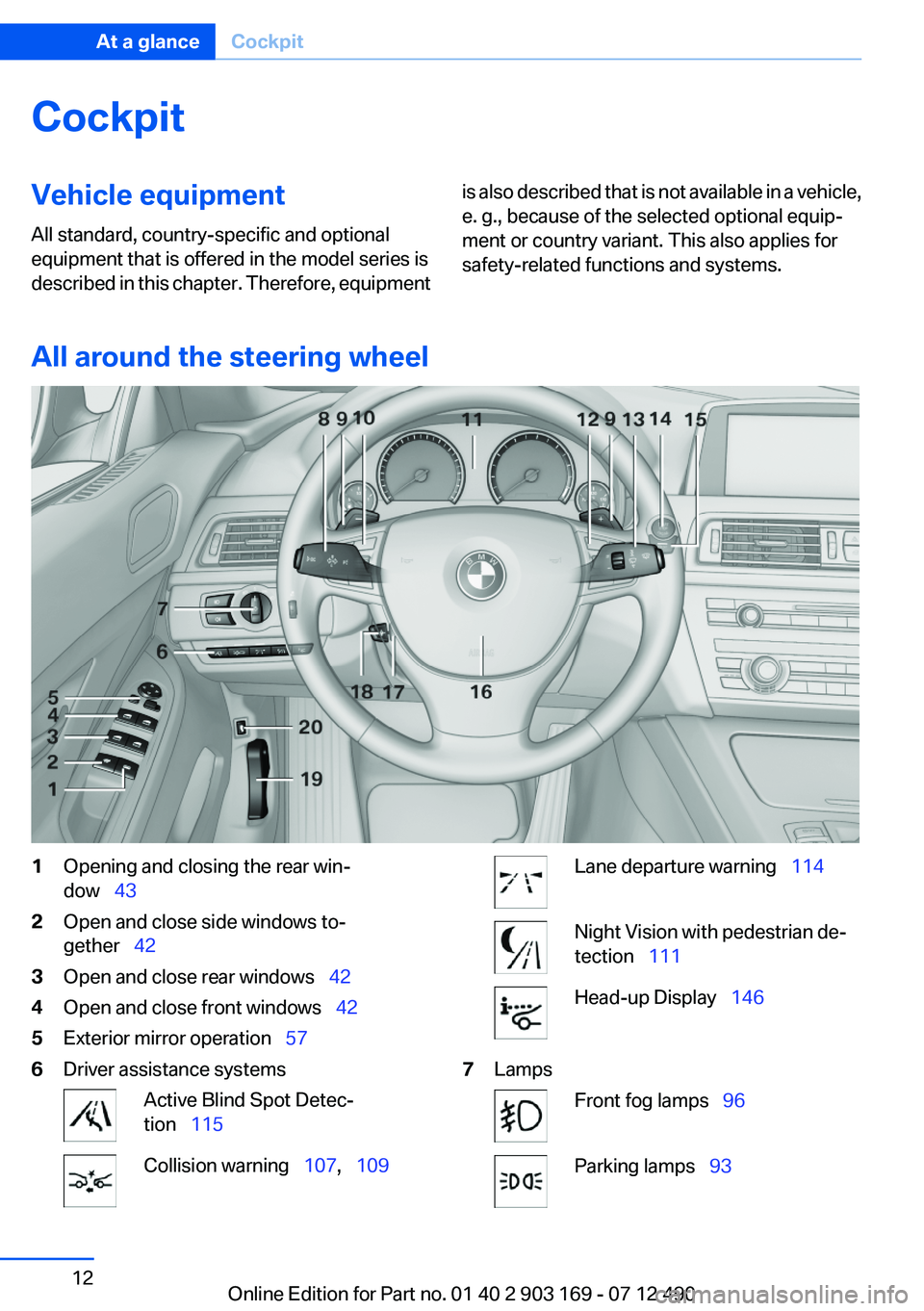
All around the steering wheel
1Opening and closing the rear win‐
dow 432Open and close side windows to‐
gether 423Open and close rear windows 424Open and close front windows 425Exterior mirror operation 576Driver assistance systemsActive Blind Spot Detec‐
tion 115Collision warning 107, 109Lane departure warning 114Night Vision with pedestrian de‐
tection 111Head-up Display 1467LampsFront fog lamps 96Parking lamps 93Seite 12At a glanceCockpit12
Online Edition for Part no. 01 40 2 903 169 - 07 12 490
Page 33 of 240
Using the guest profile
The guest profile can be used to make individual
settings without affecting the three Personal
Profiles.
This can be useful for drivers who are using the
vehicle temporarily and do not have their own
profile.1."Settings"2."Profiles"3.The current profile is selected.4.Open "Guest".5.Adjust the settings.
Note: the guest profile cannot be renamed.
Display profile list during start
The profile list can be displayed during each
start for selecting the desired profile.
1."Settings"2."Profiles"3.Open "Options".4."Display user list at startup"
Personal Profile settings
The following functions and settings can be
stored in a profile.
More information on the settings can be found
under:
▷Active Cruise Control: collision warning.▷Collision warning: warning time, last setting
on/off.▷Exterior mirror position.▷CD/Multimedia: audio source listened to
last.▷Driving Experience Switch: sport program.▷Driver's seat position: automatic retrieval af‐
ter unlocking.▷Programmable memory buttons: assign‐
ment.▷Head-up Display: selection, brightness, po‐
sition and rotation of the display.▷Headlamp courtesy delay feature: time set‐
ting.▷Tone: tone settings.▷Automatic climate control: settings.▷Steering wheel position.▷Navigation: map views, route criteria, voice
output on/off.▷Night Vision with pedestrian detection: se‐
lection of functions and type of display.▷Park Distance Control PDC: adjusting the
signal tone volume.▷Radio: stored stations, station listened to
last, special settings.▷Backup camera: selection of functions and
type of display.▷Side View: selection of the display type.▷Language on the Control Display.▷Lane departure warning: last setting, on/off.▷Active Blind Spot Detection: last setting, on/
off.▷Daytime running lights: current setting.▷Triple turn signal activation.▷Locking the vehicle: after a brief period or
after starting to drive.
Central locking system
The concept
The central locking system becomes active
when the driver's door is closed.
The system simultaneously engages and re‐
leases the locks on the following:
▷Doors.▷Compartment in the center armrest.▷Trunk lid.▷Fuel filler flap.Seite 33Opening and closingControls33
Online Edition for Part no. 01 40 2 903 169 - 07 12 490
Page 81 of 240
Instrument display
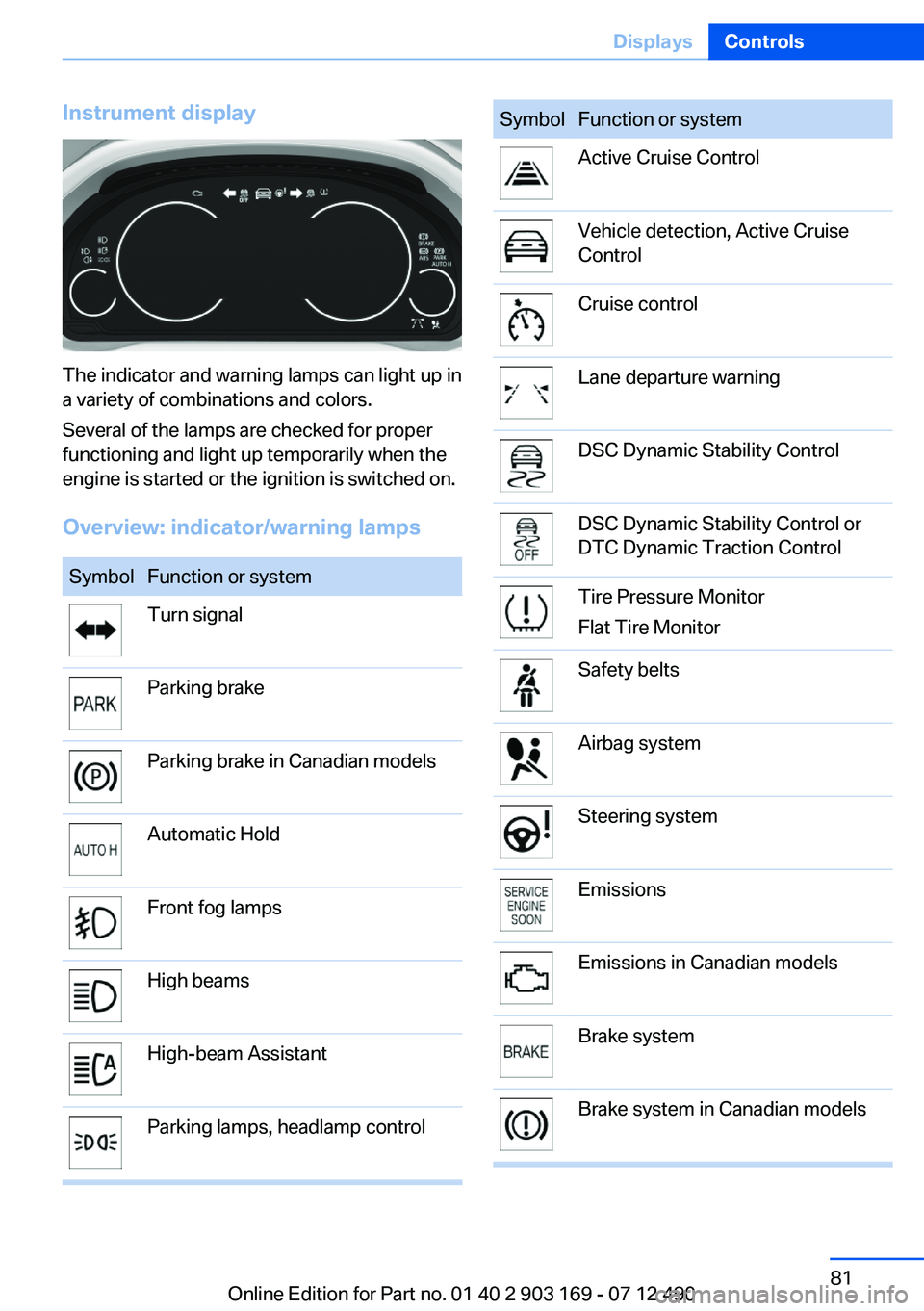
The indicator and warning lamps can light up in
a variety of combinations and colors.
Several of the lamps are checked for proper
functioning and light up temporarily when the
engine is started or the ignition is switched on.
Overview: indicator/warning lamps
SymbolFunction or systemTurn signalParking brakeParking brake in Canadian modelsAutomatic HoldFront fog lampsHigh beamsHigh-beam AssistantParking lamps, headlamp controlSymbolFunction or systemActive Cruise ControlVehicle detection, Active Cruise
ControlCruise controlLane departure warningDSC Dynamic Stability ControlDSC Dynamic Stability Control or
DTC Dynamic Traction ControlTire Pressure Monitor
Flat Tire MonitorSafety beltsAirbag systemSteering systemEmissionsEmissions in Canadian modelsBrake systemBrake system in Canadian modelsSeite 81DisplaysControls81
Online Edition for Part no. 01 40 2 903 169 - 07 12 490
Page 104 of 240
If an identification is not possible, please
contact the service center.2.Rectify the flat tire.
Use of tire sealant, e.g., the Mobility System,
may damage the TPM wheel electronics. In
this case, have the electronics checked at
the next opportunity and have them re‐
placed if necessary.
Run-flat tires
Maximum speed
You can continue driving with a damaged tire at
speeds up to 50 mph/80 km/h.
Continued driving with a flat tire
If continuing to drive with a damaged tire:
1.Avoid sudden braking and steering maneu‐
vers.2.Do not exceed a speed of 50 mph/80 km/h.3.Check the air pressure in all four tires at the
next opportunity.
If the tire inflation pressure in all four tires is
correct, the Tire Pressure Monitor may not
have been initialized. In this case, initialize
the system.
Possible driving distance with complete loss of
tire inflation pressure:
The possible driving distance after a loss of tire
inflation pressure depends on the cargo load
and the driving style and conditions.
For a vehicle containing an average load, the
possible driving distance is approx.
50 miles/80 km.
When the vehicle is driven with a damaged tire,
its handling characteristics change, e.g., re‐
duced lane stability during braking, a longer
braking distance, and altered self-steering
properties. Adjust your driving style accord‐
ingly. Avoid abrupt steering maneuvers or driv‐
ing over obstacles, e.g., curbs, potholes, etc.
Because the possible driving distance depends
on how the vehicle is used during the trip, the
actual distance may be smaller or greater de‐
pending on the driving speed, road conditions,
external temperature, cargo load, etc.
Continued driving with a flat tire
Drive moderately and do not exceed a
speed of 50 mph/80 km/h.
A loss of tire inflation pressure results in a
change in the handling characteristics, e.g., re‐
duced lane stability during braking, a longer
braking distance and altered self-steering prop‐
erties.◀
Final tire failure
Vibrations or loud noises while driving can
indicate the final failure of the tire. Reduce speed
and stop; otherwise, pieces of the tire could
come loose and cause an accident. Do not con‐
tinue driving, and contact your service center. ◀
Message when the system was not
reset
A Check Control message is displayed.
The system detected a wheel change but was
not reset.
Warnings regarding the current tire inflation
pressure are not reliable.
Check the tire inflation pressure and reset the
system.
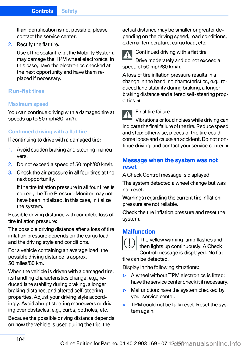
Malfunction The yellow warning lamp flashes and
then lights up continuously. A Check
Control message is displayed. No flat
tire can be detected.
Display in the following situations:▷A wheel without TPM electronics is fitted:
have the service center check it if necessary.▷Malfunction: have the system checked by
your service center.▷TPM could not be fully reset. Reset the sys‐
tem again.Seite 104ControlsSafety104
Online Edition for Part no. 01 40 2 903 169 - 07 12 490
Page 107 of 240
Continued driving with a flat tire
If continuing to drive with a damaged tire:1.Avoid sudden braking and steering maneu‐
vers.2.Do not exceed a speed of 50 mph/80 km/h.3.Check the air pressure in all four tires at the
next opportunity.
If the tire inflation pressure in all four tires is
correct, the Flat Tire Monitor may not have
been initialized. In this case, initialize the
system.
Possible driving distance with complete loss of
tire inflation pressure:
The possible driving distance after a loss of tire
inflation pressure depends on the cargo load
and the driving style and conditions.
For a vehicle containing an average load, the
possible driving distance is approx.
50 miles/80 km.
When the vehicle is driven with a damaged tire,
its handling characteristics change, e.g., re‐
duced lane stability during braking, a longer
braking distance, and altered self-steering
properties. Adjust your driving style accord‐
ingly. Avoid abrupt steering maneuvers or driv‐
ing over obstacles, e.g., curbs, potholes, etc.
Because the possible driving distance depends
on how the vehicle is used during the trip, the
actual distance may be smaller or greater de‐
pending on the driving speed, road conditions,
external temperature, cargo load, etc.
Continued driving with a flat tire
Drive moderately and do not exceed a
speed of 50 mph/80 km/h.
A loss of tire inflation pressure results in a
change in the handling characteristics, e.g., re‐
duced lane stability during braking, a longer
braking distance and altered self-steering prop‐
erties.◀
Final tire failure
Vibrations or loud noises while driving can
indicate the final failure of the tire. Reduce speed
and stop; otherwise, pieces of the tire could
come loose and cause an accident. Do not con‐
tinue driving, and contact your service center. ◀
Collision warning
The concept
If the vehicle does not include Active Cruise
Control with Stop & Go, the collision warning is
controlled via the camera in the base of the in‐
terior rearview mirror.
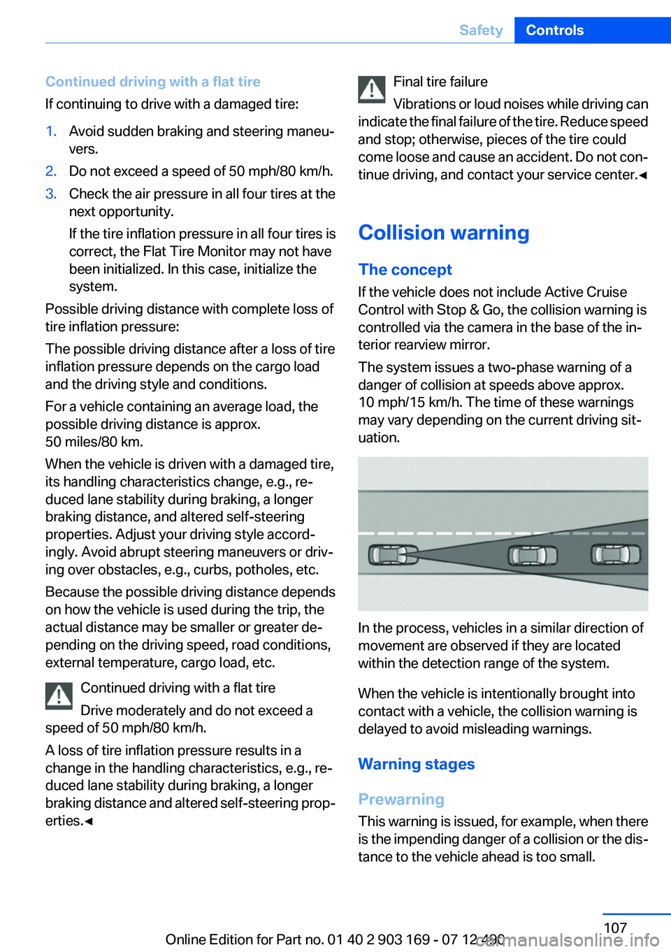
The system issues a two-phase warning of a
danger of collision at speeds above approx.
10 mph/15 km/h. The time of these warnings
may vary depending on the current driving sit‐
uation.
In the process, vehicles in a similar direction of
movement are observed if they are located
within the detection range of the system.
When the vehicle is intentionally brought into
contact with a vehicle, the collision warning is
delayed to avoid misleading warnings.
Warning stages
Prewarning
This warning is issued, for example, when there
is the impending danger of a collision or the dis‐
tance to the vehicle ahead is too small.
Seite 107SafetyControls107
Online Edition for Part no. 01 40 2 903 169 - 07 12 490
Page 114 of 240
Camera
Rain, dirt, snow, or ice can impair camera oper‐
ation.
The camera is automatically heated when the
external temperatures are low.
The camera is automatically cleaned together
with the headlamps.
Clean the lens, refer to page 214.
Lane departure warning
The concept
Starting at a specific speed, this system alerts
you when the vehicle on streets with lane mark‐
ings is about to leave the lane. Depending on the
country-specific version of the vehicle, the
speed is between 35 mph/55 km/h and
45 mph/70 km/h. When switching on the system
below this speed, a message appears in the in‐
strument cluster.
The steering wheel begins vibrating gently in the
event of warnings. The time of the warning may
vary depending on the current driving situation.
The system does not provide a warning if the
turn signal is set before leaving the lane.
Notes Personal responsibility
The system cannot serve as a substitute
for the driver's personal judgment of the course
of the road and the traffic situation.
In the event of a warning, do not jerk the steering
wheel, as you may lose control of the vehicle.◀
At a glance
Button in the vehicle
Lane departure warning
Camera
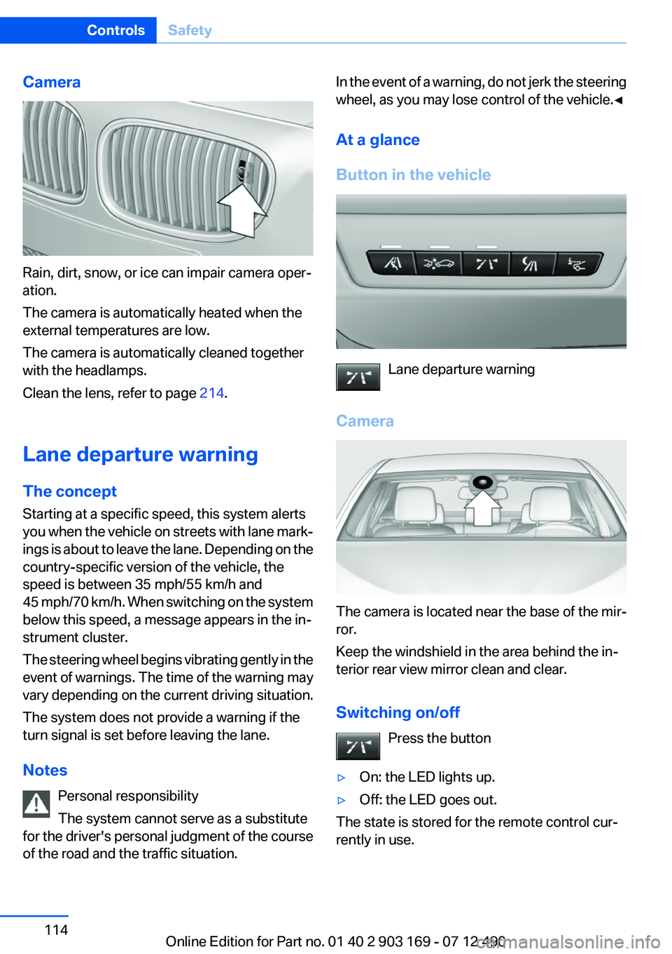
The camera is located near the base of the mir‐
ror.
Keep the windshield in the area behind the in‐
terior rear view mirror clean and clear.
Switching on/off Press the button
▷On: the LED lights up.▷Off: the LED goes out.
The state is stored for the remote control cur‐
rently in use.
Seite 114ControlsSafety114
Online Edition for Part no. 01 40 2 903 169 - 07 12 490
Page 115 of 240
Display in the instrument cluster▷Lines: system is activated.▷Arrows: at least one lane marking
was detected and warnings can be
issued.
Display in the instrument display
▷Symbol red: system is activated.▷Symbol green: at least one lane
marking was detected and warnings
can be issued.
Issued warning
If you leave the lane and if a lane marking has
been detected, the steering wheel begins vi‐
brating.
If the turn signal is set before changing the lane,
a warning is not issued.
End of warning
The warning ends:
▷Automatically after approx. 3 seconds.▷When returning to your own lane.▷When braking hard.▷When using the turn signal.
System limits
The system may not be fully functional in the
following situations:
▷In heavy fog, rain or snowfall.▷In the event of worn, poorly visible, merging,
diverging, or multiple lane markings such as
in construction areas.▷When lane markings are covered in snow,
ice, dirt or water.▷In tight curves or on narrow lanes.▷When the lane markings are covered by ob‐
jects.▷When driving very close to the vehicle in
front of you.▷When driving toward bright lights.▷When the windshield behind the interior
rearview mirror is fogged over, dirty or cov‐
ered with stickers, etc.▷During calibration of the camera immedi‐
ately after vehicle shipment.
Active Blind Spot Detection
The concept
Two radar sensors below the rear bumper mon‐
itor the area behind and next to the vehicle at
speeds above approx. 30 mph/50 km/h.
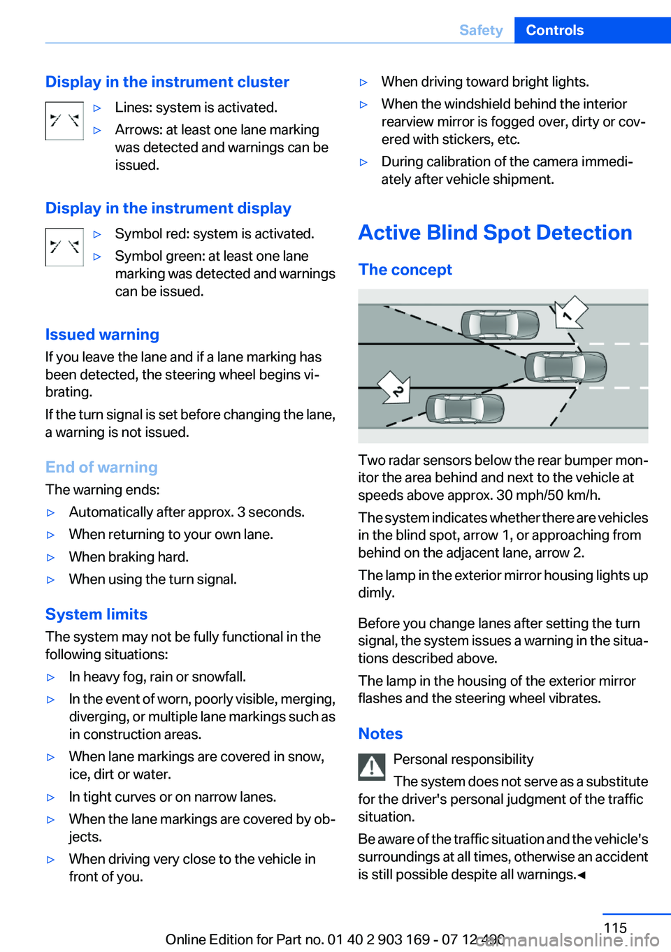
The system indicates whether there are vehicles
in the blind spot, arrow 1, or approaching from
behind on the adjacent lane, arrow 2.
The lamp in the exterior mirror housing lights up
dimly.
Before you change lanes after setting the turn
signal, the system issues a warning in the situa‐
tions described above.
The lamp in the housing of the exterior mirror
flashes and the steering wheel vibrates.
Notes Personal responsibility
The system does not serve as a substitute
for the driver's personal judgment of the traffic
situation.
Be aware of the traffic situation and the vehicle's
surroundings at all times, otherwise an accident
is still possible despite all warnings.◀
Seite 115SafetyControls115
Online Edition for Part no. 01 40 2 903 169 - 07 12 490
Page 116 of 240
At a glance
Radar sensors
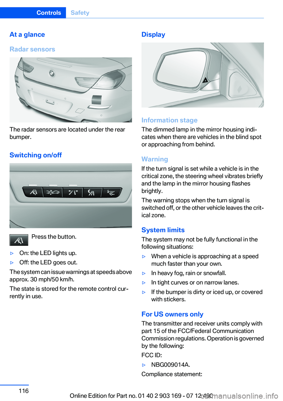
The radar sensors are located under the rear
bumper.
Switching on/off
Press the button.
▷On: the LED lights up.▷Off: the LED goes out.
The system can issue warnings at speeds above
approx. 30 mph/50 km/h.
The state is stored for the remote control cur‐
rently in use.
Display
Information stage
The dimmed lamp in the mirror housing indi‐
cates when there are vehicles in the blind spot
or approaching from behind.
Warning
If the turn signal is set while a vehicle is in the
critical zone, the steering wheel vibrates briefly
and the lamp in the mirror housing flashes
brightly.
The warning stops when the turn signal is
switched off, or the other vehicle leaves the crit‐
ical zone.
System limits
The system may not be fully functional in the
following situations:
▷When a vehicle is approaching at a speed
much faster than your own.▷In heavy fog, rain or snowfall.▷In tight curves or on narrow lanes.▷If the bumper is dirty or iced up, or covered
with stickers.
For US owners only
The transmitter and receiver units comply with
part 15 of the FCC/Federal Communication
Commission regulations. Operation is governed
by the following:
FCC ID:
▷NBG009014A.
Compliance statement:
Seite 116ControlsSafety116
Online Edition for Part no. 01 40 2 903 169 - 07 12 490