2013 BMW 650I CONVERTIBLE display
[x] Cancel search: displayPage 110 of 240
▷On: the LED lights up.▷Off: the LED goes out.
The state is stored for the remote control cur‐
rently in use.
Setting the warning time
The warning time can be set via iDrive.
These settings have no effect on the time of the
warning with which Active Cruise Control ACC
prompts the driver to intervene or brake.
1.Activate collision warning.2.Activate the desired warning time on the
Control Display.
The selected channel is stored for the remote
control currently in use.
Display
Warning stages
Prewarning
This warning is issued, for example, when there
is the impending danger of a collision or the dis‐
tance to the vehicle ahead is too small.
Acute warning with braking function
Warning of the imminent danger of a collision
when the vehicle approaches another object at
a relatively high differential speed.
The acute warning prompts the driver to inter‐
vene and, if there is the danger of a collision, is
accompanied by a braking intervention.
The braking intervention is executed with lim‐
ited braking force and for a brief period only. The
intervention will not bring the vehicle to a com‐
plete standstill.
The braking intervention is executed only if DSC
Dynamic Stability Control is switched on.
Adapting your speed and driving style
The acute warning does not relieve the
driver of the responsibility to adapt his or her
driving speed and style to the traffic condi‐
tions.◀
The braking intervention can be interrupted by
pressing on the accelerator or by actively mov‐
ing the steering wheel.
When towing or tow-starting the vehicle, switch
off the collision warning with braking function to
prevent undesired interventions.
The braking function is deactivated if the DSC
Dynamic Stability Control or DTC Dynamic
Traction Control is deactivated.
Display in the instrument cluster
The collision warning can be issued in the in‐
strument cluster, in the Head-up Display, and
acoustically.
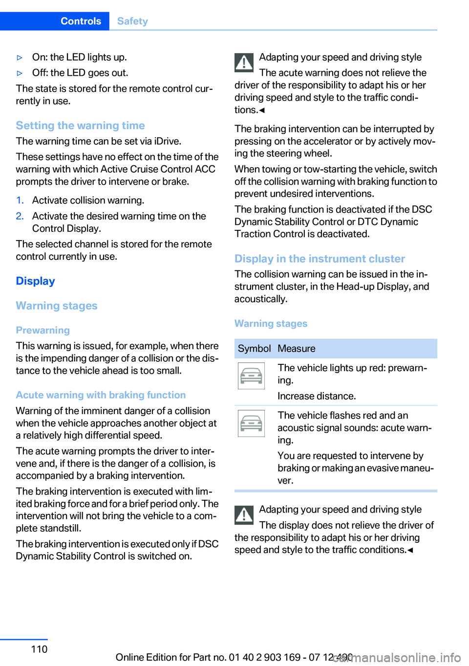
Warning stagesSymbolMeasureThe vehicle lights up red: prewarn‐
ing.
Increase distance.The vehicle flashes red and an
acoustic signal sounds: acute warn‐
ing.
You are requested to intervene by
braking or making an evasive maneu‐
ver.
Adapting your speed and driving style
The display does not relieve the driver of
the responsibility to adapt his or her driving
speed and style to the traffic conditions.◀
Seite 110ControlsSafety110
Online Edition for Part no. 01 40 2 903 169 - 07 12 490
Page 111 of 240
System limitsBe alert
Due to system limitations, warnings may
be not be issued at all, or may be issued late or
improperly. Therefore, always be alert and ready
to intervene; otherwise, there is the danger of an
accident occurring.◀
Detection range
The detection capacity of the radar sensor and
the collision warning has limitations.
This may result in the warning not being issued
or being issued late.
For example, the following situations may not be
detected:▷Slow moving vehicles when you approach
them at high speed.▷Vehicles that suddenly swerve in front of you
or sharply decelerating vehicles.▷Vehicles with an unusual rear appearance.▷Two-wheeled vehicles ahead of you.▷Pedestrians.
Functional limitations
The system may not be fully functional in the
following situations:
▷In heavy fog, rain, sprayed water or snowfall.▷In tight curves.▷If the radar sensor is dirty or obscured.
Prewarning sensitivity
Depending on the set prewarning time, this may
result in increased false warnings.
Night Vision with pedestrian
detection
The concept
Night Vision with pedestrian detection is a night
vision system.
An infrared camera records the area in front of
the vehicle and displays the image on the Con‐
trol Display.
The picture is a heat image. The system has an
integrated pedestrian detection function that
detects pedestrians and cyclists. Warm objects
that are similar in shape to human beings are
detected by the system.
Personal responsibility
Night Vision cannot replace the driver's
personal judgment of the visibility conditions
and the traffic situation. The view ahead and the
actual visibility conditions must always be the
basis on which the vehicle speed is adjusted;
otherwise, there is a risk to road safety.◀
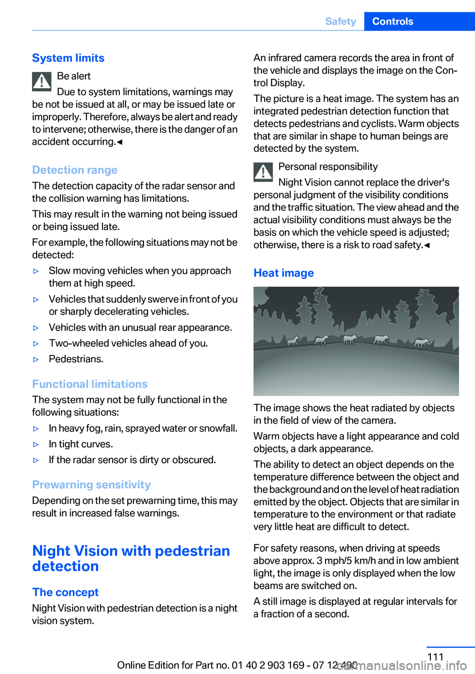
Heat image
The image shows the heat radiated by objects
in the field of view of the camera.
Warm objects have a light appearance and cold
objects, a dark appearance.
The ability to detect an object depends on the
temperature difference between the object and
the background and on the level of heat radiation
emitted by the object. Objects that are similar in
temperature to the environment or that radiate
very little heat are difficult to detect.
For safety reasons, when driving at speeds
above approx. 3 mph/5 km/h and in low ambient
light, the image is only displayed when the low
beams are switched on.
A still image is displayed at regular intervals for
a fraction of a second.
Seite 111SafetyControls111
Online Edition for Part no. 01 40 2 903 169 - 07 12 490
Page 112 of 240
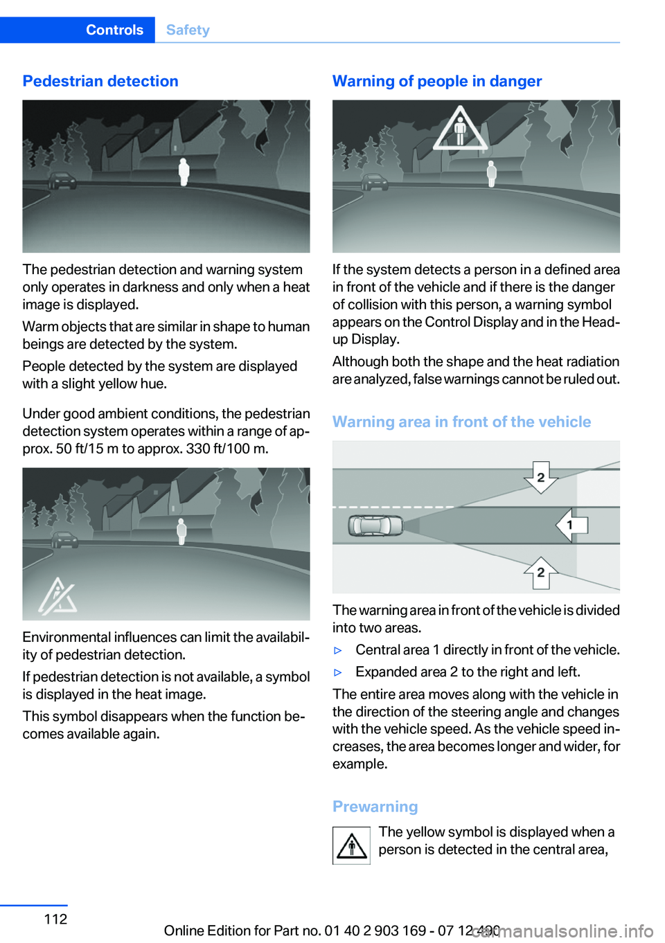
Pedestrian detection
The pedestrian detection and warning system
only operates in darkness and only when a heat
image is displayed.
Warm objects that are similar in shape to human
beings are detected by the system.
People detected by the system are displayed
with a slight yellow hue.
Under good ambient conditions, the pedestrian
detection system operates within a range of ap‐
prox. 50 ft/15 m to approx. 330 ft/100 m.
Environmental influences can limit the availabil‐
ity of pedestrian detection.
If pedestrian detection is not available, a symbol
is displayed in the heat image.
This symbol disappears when the function be‐
comes available again.
Warning of people in danger
If the system detects a person in a defined area
in front of the vehicle and if there is the danger
of collision with this person, a warning symbol
appears on the Control Display and in the Head-
up Display.
Although both the shape and the heat radiation
are analyzed, false warnings cannot be ruled out.
Warning area in front of the vehicle
The warning area in front of the vehicle is divided
into two areas.
▷Central area 1 directly in front of the vehicle.▷Expanded area 2 to the right and left.
The entire area moves along with the vehicle in
the direction of the steering angle and changes
with the vehicle speed. As the vehicle speed in‐
creases, the area becomes longer and wider, for
example.
Prewarning The yellow symbol is displayed when a
person is detected in the central area,
Seite 112ControlsSafety112
Online Edition for Part no. 01 40 2 903 169 - 07 12 490
Page 113 of 240
arrow 1, immediately in front of the vehicle.The yellow symbol is displayed when a
person detected in the extended area,
arrow 2, is moving from the right or left
to the central area.
Acute warning The red symbol is displayed and a signal
sounds. You are requested to intervene
immediately by braking or making an
evasive maneuver.
Display in the Head-up Display The warning is displayed simultane‐
ously in the Head-Up Display and on the
Control Display. The displayed symbol
can vary with the people detected. For people
located in the central area, the distance to the
person is indicated by the size of the symbol.
System limits
Basic limits
System operation is limited in situations such as
the following:▷On steep hills, in steep depressions or in
tight curves.▷When the camera is dirty or the protective
glass is damaged.▷In heavy fog, rain or snowfall.▷At very high external temperatures.
Limits of pedestrian detection
Animals are not detected by the pedestrian de‐
tection function, even if they are clearly visible in
the image.
Limited pedestrian detection:
▷People who are fully or partially covered, es‐
pecially when their heads are covered.▷People who are not in an upright position,
e.g., lying down.▷Cyclists on unconventional bicycles (e.g.,
recumbent bicycles).▷After physical damage to the system, e.g.,
after an accident.
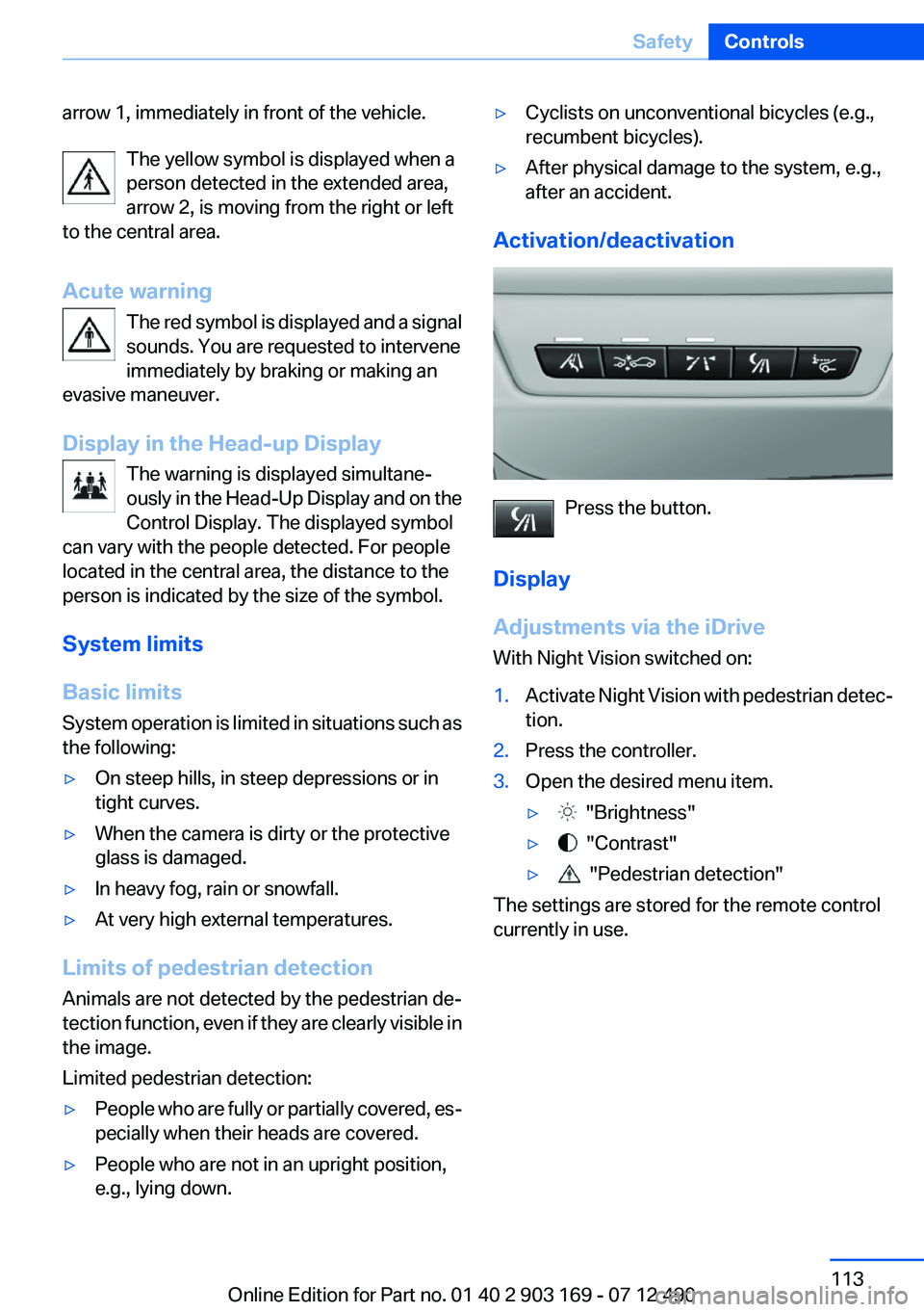
Activation/deactivation
Press the button.
Display
Adjustments via the iDrive
With Night Vision switched on:
1.Activate Night Vision with pedestrian detec‐
tion.2.Press the controller.3.Open the desired menu item.▷ "Brightness"▷ "Contrast"▷ "Pedestrian detection"
The settings are stored for the remote control
currently in use.
Seite 113SafetyControls113
Online Edition for Part no. 01 40 2 903 169 - 07 12 490
Page 115 of 240
Display in the instrument cluster▷Lines: system is activated.▷Arrows: at least one lane marking
was detected and warnings can be
issued.
Display in the instrument display
▷Symbol red: system is activated.▷Symbol green: at least one lane
marking was detected and warnings
can be issued.
Issued warning
If you leave the lane and if a lane marking has
been detected, the steering wheel begins vi‐
brating.
If the turn signal is set before changing the lane,
a warning is not issued.
End of warning
The warning ends:
▷Automatically after approx. 3 seconds.▷When returning to your own lane.▷When braking hard.▷When using the turn signal.
System limits
The system may not be fully functional in the
following situations:
▷In heavy fog, rain or snowfall.▷In the event of worn, poorly visible, merging,
diverging, or multiple lane markings such as
in construction areas.▷When lane markings are covered in snow,
ice, dirt or water.▷In tight curves or on narrow lanes.▷When the lane markings are covered by ob‐
jects.▷When driving very close to the vehicle in
front of you.▷When driving toward bright lights.▷When the windshield behind the interior
rearview mirror is fogged over, dirty or cov‐
ered with stickers, etc.▷During calibration of the camera immedi‐
ately after vehicle shipment.
Active Blind Spot Detection
The concept
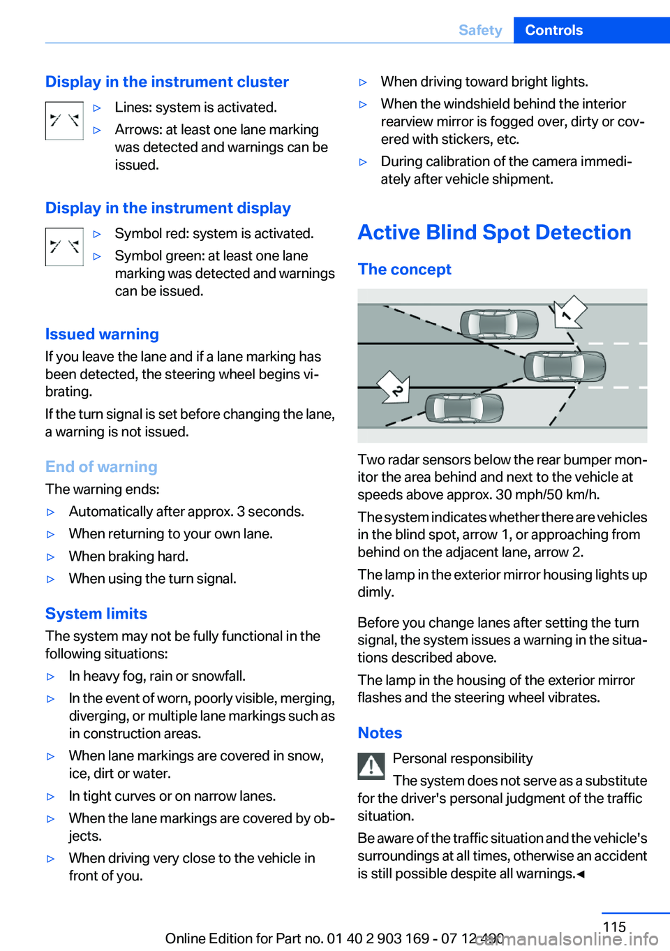
Two radar sensors below the rear bumper mon‐
itor the area behind and next to the vehicle at
speeds above approx. 30 mph/50 km/h.
The system indicates whether there are vehicles
in the blind spot, arrow 1, or approaching from
behind on the adjacent lane, arrow 2.
The lamp in the exterior mirror housing lights up
dimly.
Before you change lanes after setting the turn
signal, the system issues a warning in the situa‐
tions described above.
The lamp in the housing of the exterior mirror
flashes and the steering wheel vibrates.
Notes Personal responsibility
The system does not serve as a substitute
for the driver's personal judgment of the traffic
situation.
Be aware of the traffic situation and the vehicle's
surroundings at all times, otherwise an accident
is still possible despite all warnings.◀
Seite 115SafetyControls115
Online Edition for Part no. 01 40 2 903 169 - 07 12 490
Page 116 of 240
At a glance
Radar sensors
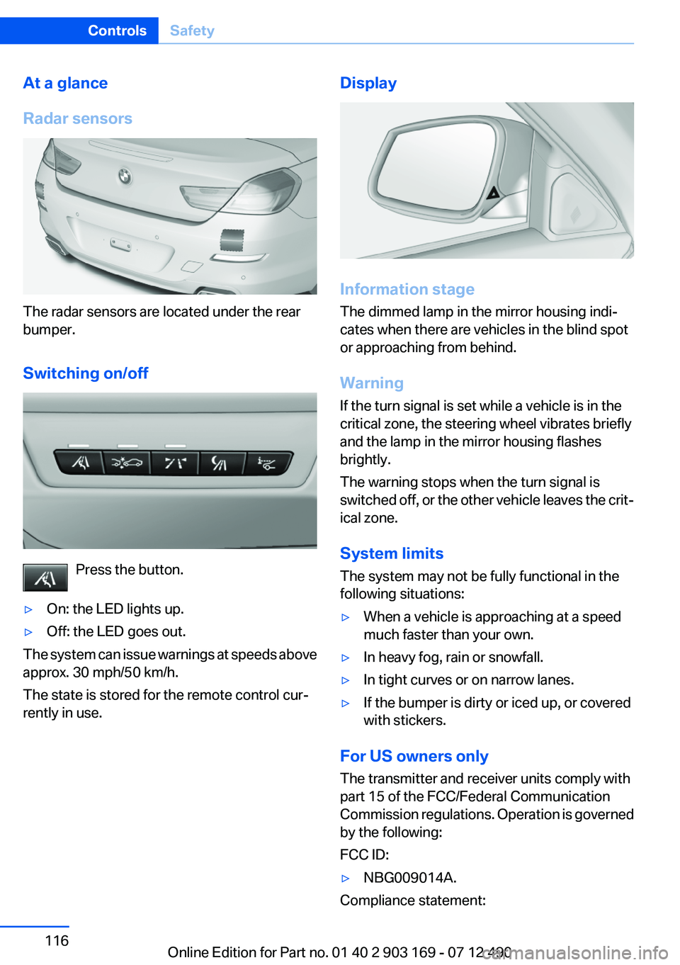
The radar sensors are located under the rear
bumper.
Switching on/off
Press the button.
▷On: the LED lights up.▷Off: the LED goes out.
The system can issue warnings at speeds above
approx. 30 mph/50 km/h.
The state is stored for the remote control cur‐
rently in use.
Display
Information stage
The dimmed lamp in the mirror housing indi‐
cates when there are vehicles in the blind spot
or approaching from behind.
Warning
If the turn signal is set while a vehicle is in the
critical zone, the steering wheel vibrates briefly
and the lamp in the mirror housing flashes
brightly.
The warning stops when the turn signal is
switched off, or the other vehicle leaves the crit‐
ical zone.
System limits
The system may not be fully functional in the
following situations:
▷When a vehicle is approaching at a speed
much faster than your own.▷In heavy fog, rain or snowfall.▷In tight curves or on narrow lanes.▷If the bumper is dirty or iced up, or covered
with stickers.
For US owners only
The transmitter and receiver units comply with
part 15 of the FCC/Federal Communication
Commission regulations. Operation is governed
by the following:
FCC ID:
▷NBG009014A.
Compliance statement:
Seite 116ControlsSafety116
Online Edition for Part no. 01 40 2 903 169 - 07 12 490
Page 117 of 240
This device complies with part 15 of the FCC
Rules. Operation is subject to the following two
conditions:▷This device may not cause harmful interfer‐
ence, and▷this device must accept any interference re‐
ceived, including interference that may
cause undesired operation.
Any unauthorized modifications or changes to
these devices could void the user's authority to
operate this equipment.
Brake force display
The concept
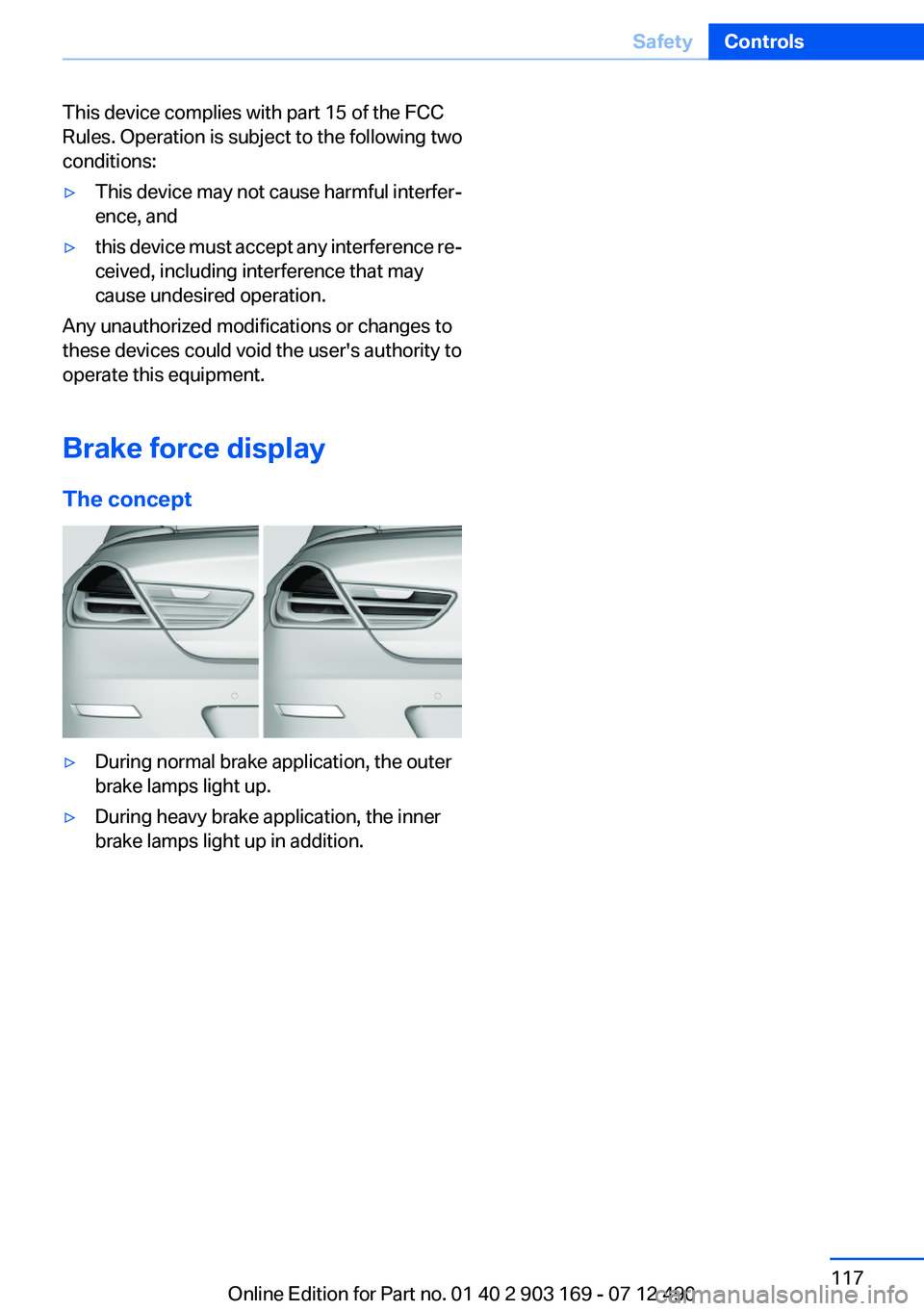
▷During normal brake application, the outer
brake lamps light up.▷During heavy brake application, the inner
brake lamps light up in addition.Seite 117SafetyControls117
Online Edition for Part no. 01 40 2 903 169 - 07 12 490
Page 119 of 240
Indicator/warning lampsThe indicator lamp flashes: DSC con‐
trols the drive forces and brake forces.
The indicator lamp lights up: DSC has
failed.
Deactivating DSC: DSC OFF
When DSC is deactivated, driving stability is re‐
duced during acceleration and when driving in
bends.
Stabilizing interventions by the Integral Active
Steering system are only performed by the rear
axle steering.
To increase vehicle stability, activate DSC again
as soon as possible.
Deactivating DSC Press and hold the button, but not lon‐
ger than approx. 10 seconds, until the
indicator lamp for DSC OFF lights up in the in‐
strument cluster and DSC OFF is displayed.
The DSC system is switched off.
Activating DSC Press the button.
DSC OFF and the DSC OFF indicator
lamp go out.
Indicator/warning lamps
When DSC is deactivated, DSC OFF is dis‐
played in the instrument cluster.
The indicator lamp lights up: DSC is de‐
activated.DTC Dynamic Traction
Control
The concept
The DTC system is a version of the DSC in which
forward momentum is optimized.
The system ensures maximum forward momen‐
tum on special road conditions, e.g., unplowed
snowy roads, but driving stability is limited.
It is therefore necessary to drive with appropri‐
ate caution.
You may find it useful to briefly activate DTC un‐
der the following special circumstances:▷When driving in slush or on uncleared,
snow-covered roads.▷When rocking the vehicle or driving off in
deep snow or on loose surfaces.▷When driving with snow chains.
Deactivating/activating DTC Dynamic
Traction Control
Activating the Dynamic Traction Control DTC
provides maximum traction on loose ground.
Driving stability is limited during acceleration
and when driving in bends.
Activating DTC Press the button.
TRACTION is displayed in the instru‐
ment cluster and the indicator lamp for DSC
OFF lights up.
Deactivating DTC Press the button again.
TRACTION and the DSC OFF indicator
lamp go out.
Indicator/warning lamps
When DTC is activated, TRACTION is displayed
in the tachometer.
Seite 119Driving stability control systemsControls119
Online Edition for Part no. 01 40 2 903 169 - 07 12 490