2013 BMW 650I CONVERTIBLE navigation system
[x] Cancel search: navigation systemPage 88 of 240
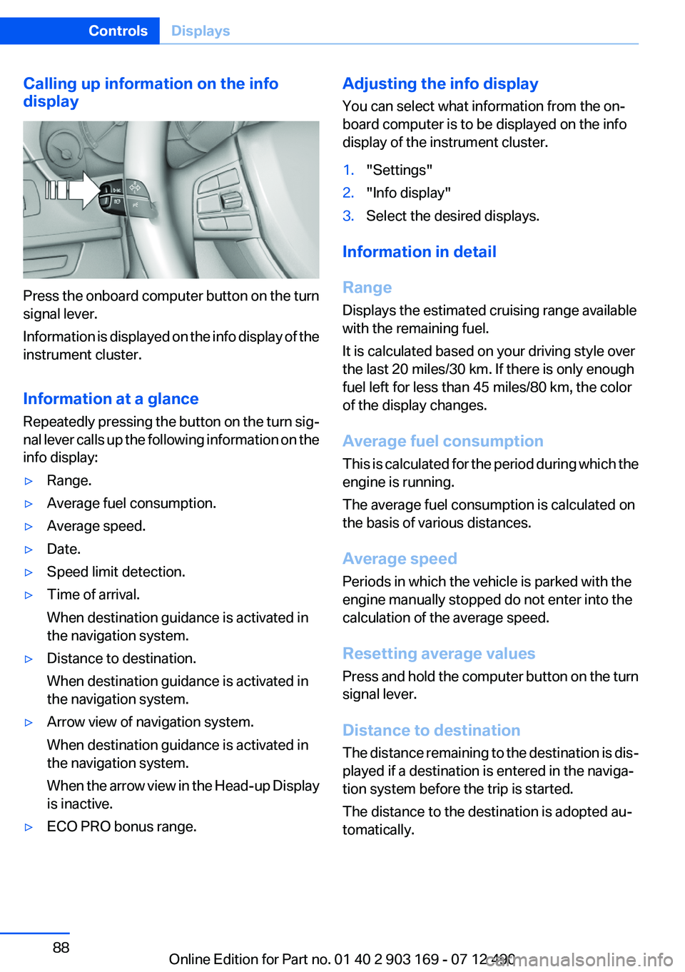
Calling up information on the info
display
Press the onboard computer button on the turn
signal lever.
Information is displayed on the info display of the
instrument cluster.
Information at a glance
Repeatedly pressing the button on the turn sig‐
nal lever calls up the following information on the
info display:
▷Range.▷Average fuel consumption.▷Average speed.▷Date.▷Speed limit detection.▷Time of arrival.
When destination guidance is activated in
the navigation system.▷Distance to destination.
When destination guidance is activated in
the navigation system.▷Arrow view of navigation system.
When destination guidance is activated in
the navigation system.
When the arrow view in the Head-up Display
is inactive.▷ECO PRO bonus range.Adjusting the info display
You can select what information from the on‐
board computer is to be displayed on the info
display of the instrument cluster.1."Settings"2."Info display"3.Select the desired displays.
Information in detail
Range
Displays the estimated cruising range available
with the remaining fuel.
It is calculated based on your driving style over
the last 20 miles/30 km. If there is only enough
fuel left for less than 45 miles/80 km, the color
of the display changes.
Average fuel consumption
This is calculated for the period during which the
engine is running.
The average fuel consumption is calculated on
the basis of various distances.
Average speed
Periods in which the vehicle is parked with the
engine manually stopped do not enter into the
calculation of the average speed.
Resetting average values
Press and hold the computer button on the turn
signal lever.
Distance to destination
The distance remaining to the destination is dis‐
played if a destination is entered in the naviga‐
tion system before the trip is started.
The distance to the destination is adopted au‐
tomatically.
Seite 88ControlsDisplays88
Online Edition for Part no. 01 40 2 903 169 - 07 12 490
Page 89 of 240
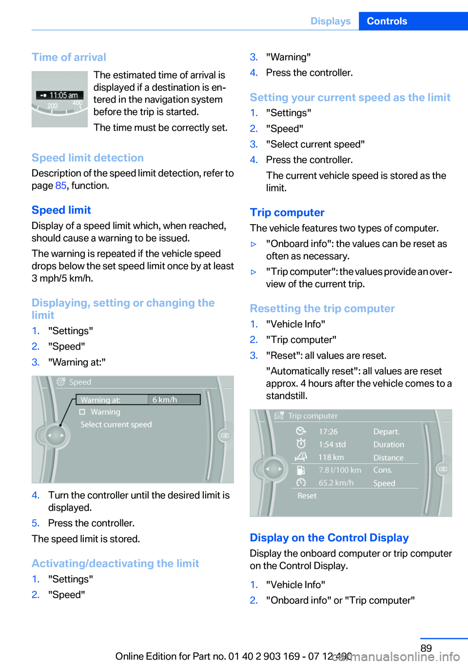
Time of arrivalThe estimated time of arrival is
displayed if a destination is en‐
tered in the navigation system
before the trip is started.
The time must be correctly set.
Speed limit detection
Description of the speed limit detection, refer to
page 85, function.
Speed limit
Display of a speed limit which, when reached,
should cause a warning to be issued.
The warning is repeated if the vehicle speed
drops below the set speed limit once by at least
3 mph/5 km/h.
Displaying, setting or changing the
limit1."Settings"2."Speed"3."Warning at:"4.Turn the controller until the desired limit is
displayed.5.Press the controller.
The speed limit is stored.
Activating/deactivating the limit
1."Settings"2."Speed"3."Warning"4.Press the controller.
Setting your current speed as the limit
1."Settings"2."Speed"3."Select current speed"4.Press the controller.
The current vehicle speed is stored as the
limit.
Trip computer
The vehicle features two types of computer.
▷"Onboard info": the values can be reset as
often as necessary.▷" Trip computer": the values provide an over‐
view of the current trip.
Resetting the trip computer
1."Vehicle Info"2."Trip computer"3."Reset": all values are reset.
"Automatically reset": all values are reset
approx. 4 hours after the vehicle comes to a
standstill.
Display on the Control Display
Display the onboard computer or trip computer
on the Control Display.
1."Vehicle Info"2."Onboard info" or "Trip computer"Seite 89DisplaysControls89
Online Edition for Part no. 01 40 2 903 169 - 07 12 490
Page 99 of 240
▷Keep at a distance from the airbags.▷Always grasp the steering wheel on the
steering wheel rim, holding your hands at
the 3 o'clock and 9 o'clock positions, to keep
the danger of injury to your hands or arms as
low as possible if the airbag is triggered.▷There should be no people, animals, or ob‐
jects between an airbag and a person.▷Do not use the cover of the front airbag on
the front passenger side as a storage area.▷Keep the dashboard and window on the
front passenger side clear, i.e., do not cover
with adhesive labels or coverings, and do not
attach holders such as for navigation instru‐
ments and mobile phones.▷Make sure that the front passenger is sitting
correctly, i.e., keeps his or her feet and legs
in the footwell; otherwise, leg injuries can
occur if the front airbag is triggered.▷Do not place slip covers, seat cushions or
other objects on the front passenger seat
that are not approved specifically for seats
with integrated side airbags.▷Do not hang pieces of clothing, such as jack‐
ets, over the backrests.▷Make sure that occupants keep their heads
away from the side airbag; otherwise, inju‐
ries can occur if the airbags are deployed.▷Do not remove the airbag restraint system.▷Do not remove the steering wheel.▷Do not apply adhesive materials to the air‐
bag cover panels, cover them or modify
them in any way.▷Never modify either the individual compo‐
nents or the wiring in the airbag system. This
also applies to steering wheel covers, the
dashboard, and the seats.◀
Even when all instructions are followed closely,
injury from contact with the airbags cannot be
ruled out in certain situations.
The ignition and inflation noise may lead to
short-term and, in most cases, temporary hear‐
ing impairment in sensitive individuals.
In the case of a malfunction, deactivation
and after triggering of the airbags
Do not touch the individual components imme‐
diately after the system has been triggered; oth‐
erwise, there is the danger of burns.
Only have the airbags checked, repaired or dis‐
mantled and the airbag generator scrapped by
your service center or a workshop that has the
necessary authorization for handling explosives.
Non-professional attempts to service the sys‐
tem could lead to failure in an emergency or un‐
desired triggering of the airbag, either of which
could result in injury.◀
Warnings and information on the airbags are
also found on the sun visors.
Functional readiness of the airbag
system
When the ignition is switch on, the warn‐
ing lamp in the instrument cluster lights
up briefly and thereby indicates the op‐
erational readiness of the entire airbag system
and the belt tensioner.
Airbag system malfunctioning▷Warning lamp does not come on when the
ignition is turned on.▷The warning lamp lights up continuously.
When there is a malfunction, have the air‐
bag system checked immediately
When there is a malfunction, have the airbag
system checked immediately; otherwise, there
is a risk that the system does not function as ex‐
pected in the event of an accident despite cor‐
responding severity of the accident.◀
Automatic deactivation of the front
passenger airbags
The system determines whether the front pas‐
senger seat is occupied by measuring the re‐
sistance of the human body.
Seite 99SafetyControls99
Online Edition for Part no. 01 40 2 903 169 - 07 12 490
Page 135 of 240
At a glance
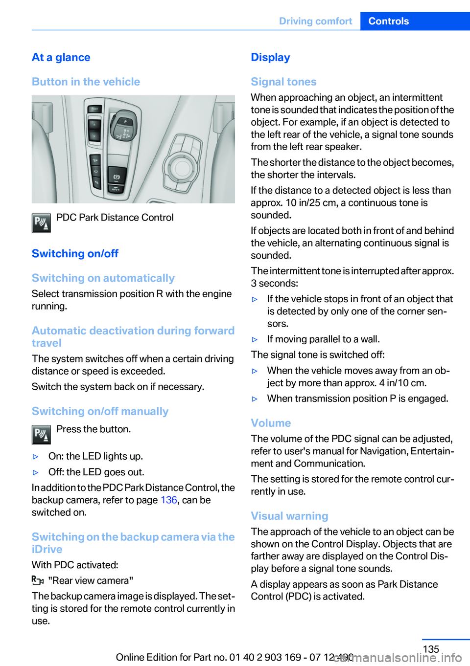
Button in the vehicle
PDC Park Distance Control
Switching on/off
Switching on automatically
Select transmission position R with the engine
running.
Automatic deactivation during forward
travel
The system switches off when a certain driving
distance or speed is exceeded.
Switch the system back on if necessary.
Switching on/off manually Press the button.
▷On: the LED lights up.▷Off: the LED goes out.
In addition to the PDC Park Distance Control, the
backup camera, refer to page 136, can be
switched on.
Switching on the backup camera via the
iDrive
With PDC activated:
"Rear view camera"
The backup camera image is displayed. The set‐
ting is stored for the remote control currently in
use.
Display
Signal tones
When approaching an object, an intermittent
tone is sounded that indicates the position of the
object. For example, if an object is detected to
the left rear of the vehicle, a signal tone sounds
from the left rear speaker.
The shorter the distance to the object becomes,
the shorter the intervals.
If the distance to a detected object is less than
approx. 10 in/25 cm, a continuous tone is
sounded.
If objects are located both in front of and behind
the vehicle, an alternating continuous signal is
sounded.
The intermittent tone is interrupted after approx.
3 seconds:▷If the vehicle stops in front of an object that
is detected by only one of the corner sen‐
sors.▷If moving parallel to a wall.
The signal tone is switched off:
▷When the vehicle moves away from an ob‐
ject by more than approx. 4 in/10 cm.▷When transmission position P is engaged.
Volume
The volume of the PDC signal can be adjusted,
refer to user's manual for Navigation, Entertain‐
ment and Communication.
The setting is stored for the remote control cur‐
rently in use.
Visual warning
The approach of the vehicle to an object can be
shown on the Control Display. Objects that are
farther away are displayed on the Control Dis‐
play before a signal tone sounds.
A display appears as soon as Park Distance
Control (PDC) is activated.
Seite 135Driving comfortControls135
Online Edition for Part no. 01 40 2 903 169 - 07 12 490
Page 146 of 240
Head-up Display
The concept
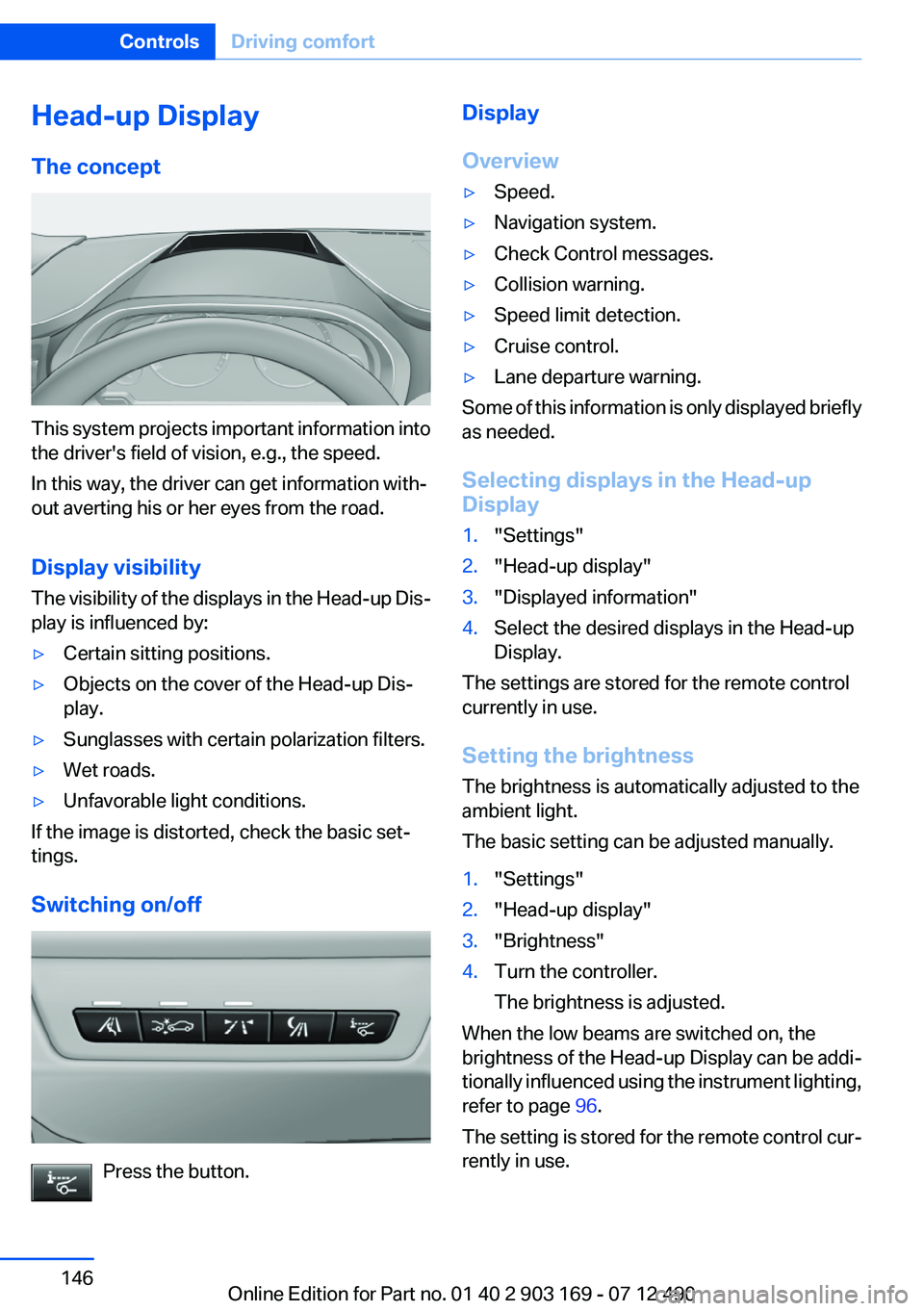
This system projects important information into
the driver's field of vision, e.g., the speed.
In this way, the driver can get information with‐
out averting his or her eyes from the road.
Display visibility
The visibility of the displays in the Head-up Dis‐
play is influenced by:
▷Certain sitting positions.▷Objects on the cover of the Head-up Dis‐
play.▷Sunglasses with certain polarization filters.▷Wet roads.▷Unfavorable light conditions.
If the image is distorted, check the basic set‐
tings.
Switching on/off
Press the button.
Display
Overview▷Speed.▷Navigation system.▷Check Control messages.▷Collision warning.▷Speed limit detection.▷Cruise control.▷Lane departure warning.
Some of this information is only displayed briefly
as needed.
Selecting displays in the Head-up
Display
1."Settings"2."Head-up display"3."Displayed information"4.Select the desired displays in the Head-up
Display.
The settings are stored for the remote control
currently in use.
Setting the brightness
The brightness is automatically adjusted to the
ambient light.
The basic setting can be adjusted manually.
1."Settings"2."Head-up display"3."Brightness"4.Turn the controller.
The brightness is adjusted.
When the low beams are switched on, the
brightness of the Head-up Display can be addi‐
tionally influenced using the instrument lighting,
refer to page 96.
The setting is stored for the remote control cur‐
rently in use.
Seite 146ControlsDriving comfort146
Online Edition for Part no. 01 40 2 903 169 - 07 12 490
Page 202 of 240
Lug bolt lock
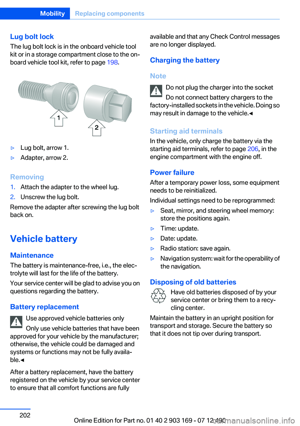
The lug bolt lock is in the onboard vehicle tool
kit or in a storage compartment close to the on‐
board vehicle tool kit, refer to page 198.▷Lug bolt, arrow 1.▷Adapter, arrow 2.
Removing
1.Attach the adapter to the wheel lug.2.Unscrew the lug bolt.
Remove the adapter after screwing the lug bolt
back on.
Vehicle battery
Maintenance
The battery is maintenance-free, i.e., the elec‐
trolyte will last for the life of the battery.
Your service center will be glad to advise you on
questions regarding the battery.
Battery replacement Use approved vehicle batteries only
Only use vehicle batteries that have been
approved for your vehicle by the manufacturer;
otherwise, the vehicle could be damaged and
systems or functions may not be fully availa‐
ble.◀
After a battery replacement, have the battery
registered on the vehicle by your service center
to ensure that all comfort functions are fully
available and that any Check Control messages
are no longer displayed.
Charging the battery
Note Do not plug the charger into the socket
Do not connect battery chargers to the
factory-installed sockets in the vehicle. Doing so
may result in damage to the vehicle.◀
Starting aid terminals
In the vehicle, only charge the battery via the
starting aid terminals, refer to page 206, in the
engine compartment with the engine off.
Power failure
After a temporary power loss, some equipment
needs to be reinitialized.
Individual settings need to be reprogrammed:▷Seat, mirror, and steering wheel memory:
store the positions again.▷Time: update.▷Date: update.▷Radio station: save again.▷Navigation system: wait for the operability of
the navigation.
Disposing of old batteries
Have old batteries disposed of by your
service center or bring them to a recy‐
cling center.
Maintain the battery in an upright position for
transport and storage. Secure the battery so
that it does not tip over during transport.
Seite 202MobilityReplacing components202
Online Edition for Part no. 01 40 2 903 169 - 07 12 490
Page 206 of 240
Roadside Assistance
The Roadside Assistance phone number can be
viewed on the iDrive or a connection to Roadside
Assistance can be established directly. Phone,
see user's manual for Navigation, Entertainment
and Communication.
Jump-starting
Notes
If the battery is discharged, an engine can be
started using the battery of another vehicle and
two jumper cables. Only use jumper cables with
fully insulated clamp handles.
To prevent personal injury or damage to both
vehicles, adhere strictly to the following proce‐
dure.
Do not touch live parts
To avoid the risk of potentially fatal injury,
always avoid all contact with electrical compo‐
nents while the engine is running.◀
Preparation1.Check whether the battery of the other ve‐
hicle has a voltage of 12 volts. This informa‐
tion can be found on the battery.2.Switch off the engine of the assisting vehi‐
cle.3.Switch off any electronic systems/power
consumers in both vehicles.
Bodywork contact between vehicles
Make sure that there is no contact be‐
tween the bodywork of the two vehicles; other‐
wise, there is the danger of short circuits.◀
Starting aid terminals Connecting order
Connect the jumper cables in the correct
order; otherwise, there is the danger of injury
from sparking.◀
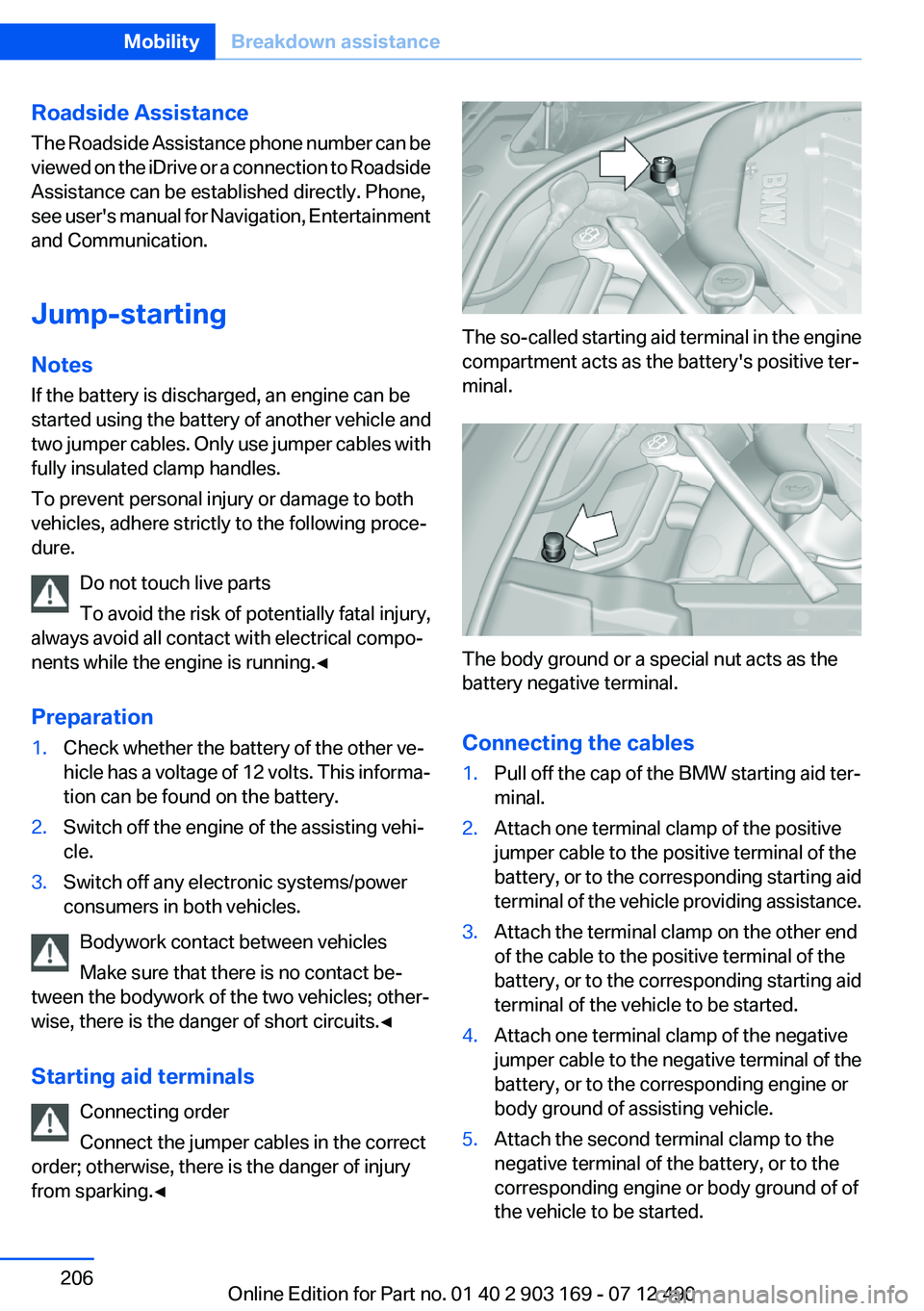
The so-called starting aid terminal in the engine
compartment acts as the battery's positive ter‐
minal.
The body ground or a special nut acts as the
battery negative terminal.
Connecting the cables
1.Pull off the cap of the BMW starting aid ter‐
minal.2.Attach one terminal clamp of the positive
jumper cable to the positive terminal of the
battery, or to the corresponding starting aid
terminal of the vehicle providing assistance.3.Attach the terminal clamp on the other end
of the cable to the positive terminal of the
battery, or to the corresponding starting aid
terminal of the vehicle to be started.4.Attach one terminal clamp of the negative
jumper cable to the negative terminal of the
battery, or to the corresponding engine or
body ground of assisting vehicle.5.Attach the second terminal clamp to the
negative terminal of the battery, or to the
corresponding engine or body ground of of
the vehicle to be started.Seite 206MobilityBreakdown assistance206
Online Edition for Part no. 01 40 2 903 169 - 07 12 490
Page 223 of 240
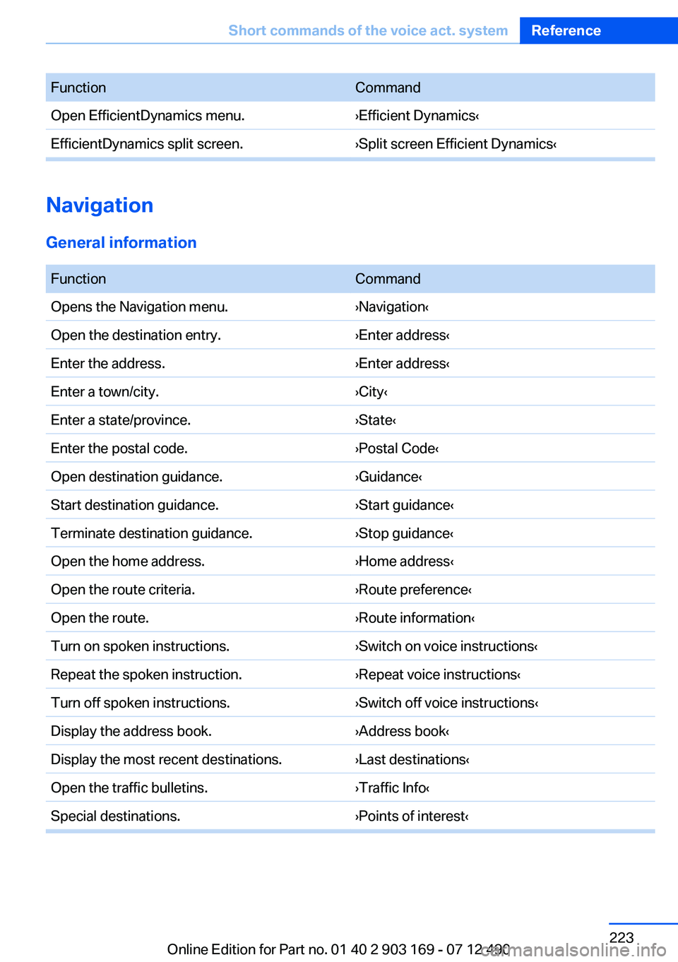
FunctionCommandOpen EfficientDynamics menu.›Efficient Dynamics‹EfficientDynamics split screen.›Split screen Efficient Dynamics‹
Navigation
General information
FunctionCommandOpens the Navigation menu.›Navigation‹Open the destination entry.›Enter address‹Enter the address.›Enter address‹Enter a town/city.›City‹Enter a state/province.›State‹Enter the postal code.›Postal Code‹Open destination guidance.›Guidance‹Start destination guidance.›Start guidance‹Terminate destination guidance.›Stop guidance‹Open the home address.›Home address‹Open the route criteria.›Route preference‹Open the route.›Route information‹Turn on spoken instructions.›Switch on voice instructions‹Repeat the spoken instruction.›Repeat voice instructions‹Turn off spoken instructions.›Switch off voice instructions‹Display the address book.›Address book‹Display the most recent destinations.›Last destinations‹Open the traffic bulletins.›Traffic Info‹Special destinations.›Points of interest‹Seite 223Short commands of the voice act. systemReference223
Online Edition for Part no. 01 40 2 903 169 - 07 12 490