2013 BMW 640I GRAN COUPE check engine
[x] Cancel search: check enginePage 31 of 305
4.Insert a battery of the same type with the
positive side facing upwards.5.Press the cover closed.
Take the used battery to a recycling cen‐
ter or to your service center.
New remote controls
You can obtain new remote controls from your
service center.
Loss of the remote controls
Lost remote controls can be blocked by your
service center.
Emergency detection of remote control
It is possible to switch on the ignition or start the
engine in situations such as the following:
▷Interference of radio transmission to remote
control by external sources.▷Discharged battery in the remote control.▷Interference of radio transmission by mobile
devices in close proximity to the remote
control.▷Interference of radio transmission by
charger while charging items such as mobile
devices in the vehicle.
A Check Control message is displayed if an at‐
tempt is made to switch on the ignition or start
the engine.
Starting the engine in case of
emergency detection of remote control
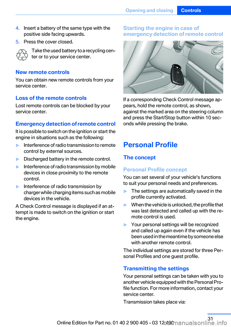
If a corresponding Check Control message ap‐
pears, hold the remote control, as shown,
against the marked area on the steering column
and press the Start/Stop button within 10 sec‐
onds while pressing the brake.
Personal Profile
The concept
Personal Profile concept
You can set several of your vehicle's functions
to suit your personal needs and preferences.
▷The settings are automatically saved in the
profile currently activated.▷When the vehicle is unlocked, the profile that
was last detected and called up with the re‐
mote control is used.▷Your personal settings will be recognized
and called up again even if the vehicle has
been used in the meantime by someone else
with another remote control.
The individual settings are stored for three Per‐
sonal Profiles and one guest profile.
Transmitting the settings
Your personal settings can be taken with you to
another vehicle equipped with the Personal Pro‐
file function. For more information, contact your
service center.
Transmission takes place via:
Seite 31Opening and closingControls31
Online Edition for Part no. 01 40 2 900 405 - 03 12 490
Page 61 of 305
Preventing an automatic engine stop
with automatic transmission
The concept
To make it possible to drive away very quickly,
such as at an intersection, the automatic engine
stop can be actively prevented.
Preventing an engine stop using the
brake pedal
The engine stop can be actively prevented
within one second after the vehicle comes to a
standstill.▷Immediately after the vehicle comes to a
standstill, briefly press the brake pedal
forcefully.▷Then press the brake pedal with normal
braking force.
Activating/deactivating the system
manually
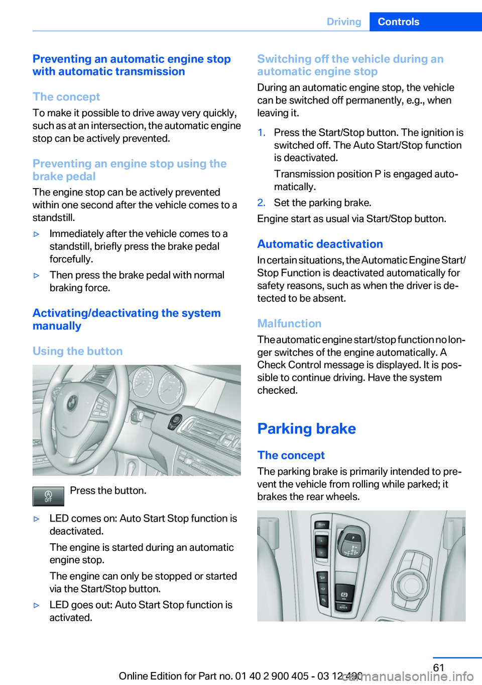
Using the button
Press the button.
▷LED comes on: Auto Start Stop function is
deactivated.
The engine is started during an automatic
engine stop.
The engine can only be stopped or started
via the Start/Stop button.▷LED goes out: Auto Start Stop function is
activated.Switching off the vehicle during an
automatic engine stop
During an automatic engine stop, the vehicle
can be switched off permanently, e.g., when
leaving it.1.Press the Start/Stop button. The ignition is
switched off. The Auto Start/Stop function
is deactivated.
Transmission position P is engaged auto‐
matically.2.Set the parking brake.
Engine start as usual via Start/Stop button.
Automatic deactivation
In certain situations, the Automatic Engine Start/
Stop Function is deactivated automatically for
safety reasons, such as when the driver is de‐
tected to be absent.
Malfunction
The automatic engine start/stop function no lon‐
ger switches of the engine automatically. A
Check Control message is displayed. It is pos‐
sible to continue driving. Have the system
checked.
Parking brake
The concept
The parking brake is primarily intended to pre‐
vent the vehicle from rolling while parked; it
brakes the rear wheels.
Seite 61DrivingControls61
Online Edition for Part no. 01 40 2 900 405 - 03 12 490
Page 72 of 305
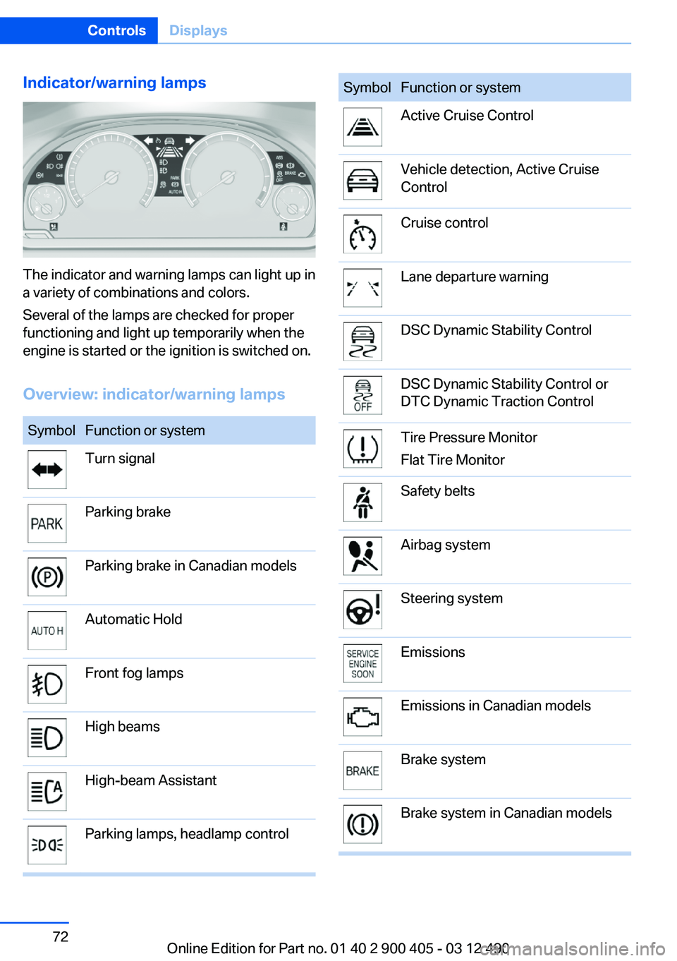
Indicator/warning lamps
The indicator and warning lamps can light up in
a variety of combinations and colors.
Several of the lamps are checked for proper
functioning and light up temporarily when the
engine is started or the ignition is switched on.
Overview: indicator/warning lamps
SymbolFunction or systemTurn signalParking brakeParking brake in Canadian modelsAutomatic HoldFront fog lampsHigh beamsHigh-beam AssistantParking lamps, headlamp controlSymbolFunction or systemActive Cruise ControlVehicle detection, Active Cruise
ControlCruise controlLane departure warningDSC Dynamic Stability ControlDSC Dynamic Stability Control or
DTC Dynamic Traction ControlTire Pressure Monitor
Flat Tire MonitorSafety beltsAirbag systemSteering systemEmissionsEmissions in Canadian modelsBrake systemBrake system in Canadian modelsSeite 72ControlsDisplays72
Online Edition for Part no. 01 40 2 900 405 - 03 12 490
Page 74 of 305
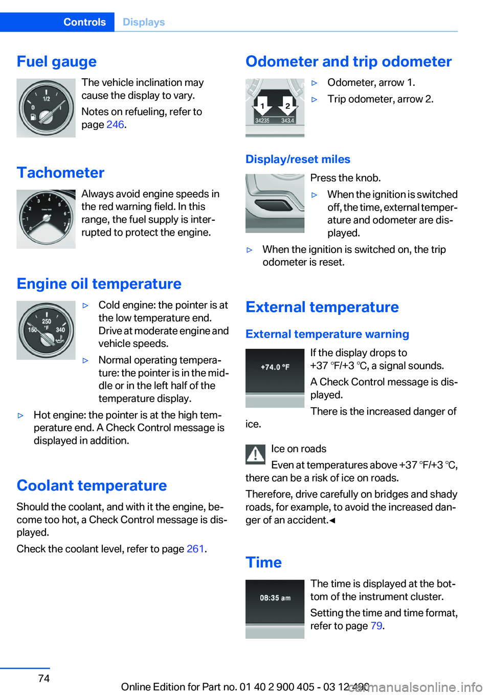
Fuel gaugeThe vehicle inclination may
cause the display to vary.
Notes on refueling, refer to
page 246.
Tachometer Always avoid engine speeds in
the red warning field. In this
range, the fuel supply is inter‐
rupted to protect the engine.
Engine oil temperature▷Cold engine: the pointer is at
the low temperature end.
Drive at moderate engine and
vehicle speeds.▷Normal operating tempera‐
ture: the pointer is in the mid‐
dle or in the left half of the
temperature display.▷Hot engine: the pointer is at the high tem‐
perature end. A Check Control message is
displayed in addition.
Coolant temperature
Should the coolant, and with it the engine, be‐
come too hot, a Check Control message is dis‐
played.
Check the coolant level, refer to page 261.
Odometer and trip odometer▷Odometer, arrow 1.▷Trip odometer, arrow 2.
Display/reset miles
Press the knob.
▷When the ignition is switched
off, the time, external temper‐
ature and odometer are dis‐
played.▷When the ignition is switched on, the trip
odometer is reset.
External temperature
External temperature warning If the display drops to
+37 ℉/+3 ℃, a signal sounds.
A Check Control message is dis‐
played.
There is the increased danger of
ice.
Ice on roads
Even at temperatures above +37 ℉/+3 ℃,
there can be a risk of ice on roads.
Therefore, drive carefully on bridges and shady
roads, for example, to avoid the increased dan‐
ger of an accident.◀
Time The time is displayed at the bot‐
tom of the instrument cluster.
Setting the time and time format,
refer to page 79.
Seite 74ControlsDisplays74
Online Edition for Part no. 01 40 2 900 405 - 03 12 490
Page 75 of 305

DateThe date is displayed in the in‐
strument cluster.
Setting the date and date format,
refer to page 80.
Range After the reserve range is
reached:▷A Check Control message is
displayed briefly.▷The remaining range is
shown on the onboard com‐
puter.▷When a dynamic driving style is used, such
as when cornering quickly, operation of the
engine is not always ensured.
The Check Control message appears continu‐
ously below a range of approx. 30 miles/50 km.
Refuel promptly
Refuel no later than at a range of
30 miles/50 km, or operation of the engine is not
ensured and damage may occur.◀
Displaying the cruising range
1."Settings"2."Info display"3."Additional indicators"
The range is displayed in the instrument cluster.
Range when destination guidance is
activated in the navigation system
When destination guidance is ac‐
tivated in the navigation system,
the range up to the destination is
displayed.
Current fuel consumption
Displays the current fuel con‐
sumption. You can check
whether you are currently driving
in an efficient and environmen‐
tally-friendly manner.
Displaying the current fuel
consumption1."Settings"2."Info display"3."Additional indicators"
The bar display for the current fuel consumption
is displayed in the instrument cluster.
Energy recovery The kinetic energy of the vehicle
is converted to electrical energy
while coasting. The vehicle bat‐
tery is partially charged and fuel
consumption can be reduced.
Service requirements
Display The driving distance or the time
to the next scheduled mainte‐
nance is displayed briefly after
the ignition is switched on.
The current service require‐
ments can be read out from the remote control
by the service specialist.
Data regarding the maintenance status or legally
mandated inspections of the vehicle are auto‐
matically transmitted to your service center be‐
fore a service due date, Automatic Service Re‐
quest, refer to page 238.
Seite 75DisplaysControls75
Online Edition for Part no. 01 40 2 900 405 - 03 12 490
Page 91 of 305
A change in the tire inflation pressure during
driving is taken into account.
A correction is only necessary if this is indicated
by the TPM
Wheels, green
The tire inflation pressure is equal to the target
state.
One wheel is yellow
A flat tire or major drop in inflation pressure in
the indicated tire.
All wheels are yellow▷A flat tire or major drop in inflation pressure
in several tires.▷The system was not reset after a wheel
change and thus warns based on the infla‐
tion pressures initialized last.▷A flat tire in one or more tires while the sys‐
tem is being reset.
Wheels, gray
The system cannot detect a flat tire. Reasons for
this may be:
▷TPM is being reset.▷Disturbance by systems or devices with the
same radio frequency.▷Malfunction.
For Canadian models: additional
information
The status display additionally shows the cur‐
rent tire inflation pressures and tire tempera‐
tures.
When correcting the tire inflation pressures,
note the following:
The tire pressure increases as the tire temper‐
ature increases.
Therefore, only correct the tire inflation pres‐
sure when the tire is at the ambient temperature.
Compare the displayed tire temperature with
the external temperature in the instrument clus‐
ter.
Resetting the system
Reset the system after each correction of the
tire inflation pressure and after every tire or
wheel change.1."Vehicle Info"2."Vehicle status"3. "Reset"4.Start the engine - do not drive away.5.Reset the tire pressure using "Reset".6.Drive away.
The tires are shown in gray and "Resetting
TPM..." is displayed.
After driving for a few minutes, the set tire infla‐
tion pressures are applied as set values. The re‐
setting process is completed automatically dur‐
ing driving. The tires are shown in green and
"TPM active" is shown on the Control Display.
The trip can be interrupted at any time. If you
drive away again, the process resumes auto‐
matically.
If a flat tire is detected during a reset, all tires are
displayed in yellow.
Low tire pressure message The yellow warning lamp lights up. A
Check Control message is displayed.
▷There is a flat tire or a major loss in
tire inflation pressure.▷The system was not reset after a wheel
change and thus warns based on the infla‐
tion pressures initialized last.1.Reduce your speed and stop cautiously.
Avoid sudden braking and steering maneu‐
vers.2.Check whether the vehicle is fitted with reg‐
ular tires or run-flat tires.Seite 91SafetyControls91
Online Edition for Part no. 01 40 2 900 405 - 03 12 490
Page 94 of 305
In the event of a pressure loss, the diameter and
therefore the rotational speed of the corre‐
sponding wheel change. This is detected and
reported as a flat tire.
Functional requirements
The system must have been initialized when the
tire inflation pressure was correct; otherwise,
reliable signaling of a flat tire is not ensured. In‐
itialize the system after each correction of the
tire inflation pressure and after every tire or
wheel change.
System limits Sudden tire damage
Sudden serious tire damage caused by
external influences cannot be indicated in ad‐
vance.◀
A natural, even pressure loss in all four tires can‐
not be detected. Therefore, check the tire infla‐
tion pressure regularly.
The system could be delayed or malfunction in
the following situations:▷When the system has not been initialized.▷When driving on a snowy or slippery road
surface.▷Sporty driving style: slip in the drive wheels,
high lateral acceleration.▷When driving with snow chains.
Status display
The current status of the Flat Tire Monitor can
be displayed on the Control Display, e.g.,
whether or not the FTM is active.
1."Vehicle Info"2."Vehicle status"3. "Flat Tire Monitor"
The status is displayed.
Initialization
The initialization process adopts the set inflation
tire pressures as reference values for the detec‐
tion of a flat tire. Initialization is started by con‐
firming the inflation pressures.
Do not initialize the system when driving with
snow chains.1."Vehicle Info"2."Vehicle status"3. "Reset"4.Start the engine - do not drive away.5.Start the initialization with "Reset".6.Drive away.
The initialization is completed while driving,
which can be interrupted at any time.
The initialization automatically continues when
driving resumes.
Indication of a flat tire The yellow warning lamp lights up. A
Check Control message is displayed.
There is a flat tire or a major loss in tire
inflation pressure.
1.Reduce your speed and stop cautiously.
Avoid sudden braking and steering maneu‐
vers.2.Check whether the vehicle is fitted with reg‐
ular tires or run-flat tires.
Run-flat tires, refer to page 255, are labeled
with a circular symbol containing the letters
RSC marked on the tire sidewall.
Do not continue driving without run-flat
tires
Do not continue driving if the vehicle is not
equipped with run-flat tires; continued driving
may result in serious accidents.◀
When a flat tire is indicated, DSC Dynamic Sta‐
bility Control is switched on if necessary.
Actions in the event of a flat tire
Normal tires
1.Identify the damaged tire.Seite 94ControlsSafety94
Online Edition for Part no. 01 40 2 900 405 - 03 12 490
Page 102 of 305
At higher speeds, the steering angle is increas‐
ingly reduced.
The rear wheels are turned to the same angle as
the front wheels.
In critical situations, Integral Active Steering can
specifically steer the front and rear wheels to
stabilize the vehicle before the driver intervenes,
e.g., when braking where road conditions differ
on the left and right sides of the vehicle.
Initializing
In rare cases, it may become necessary to initi‐
alize the Integral Active Steering.
The warning lamp lights up. A Check
Control message is displayed.1.With the engine running, turn the steering
wheel all the way to the left and right several
times in a uniform manner until the warning
lamp disappears.2.Have the system checked if the warning
lamp does not go out after moving the steer‐
ing wheel approx. 6 times or if the steering
wheel is at an angle.
Using snow chains
Ensure that the rear axle steering is deactivated
when using snow chains, refer to page 256.
Programs
The system offers two different programs.
The programs can be selected via the Driving
Experience Switch, refer to page 102.
SPORT
Consistently sporty tuning of the Integral Active
Steering for greater driving agility.
COMFORT
Balanced tuning of the Integral Active Steering
for optimal traveling comfort.
Malfunction
In the event of a malfunction, the steering wheel
must be turned further, while the vehicle re‐
sponds more sensitively to steering wheel
movements in the higher speed range.
The stability-enhancing intervention may be de‐
activated.
Proceed cautiously and drive defensively.
Have the system checked.
Driving Experience Switch
The concept
The Driving Experience Switch can be used to
adjust the driving dynamics of the vehicle. For
this purpose various programs are available for
selection that are activated via the two buttons
of the Driving Experience Switch and the DSC
OFF-button.
Operating the programsPress the buttonProgramDSC OFF
TRACTIONSPORT+
SPORT
COMFORT
COMFORT+
ECO PRO
For Dynamic Damper Control, the lower button
is labeled with COMFORT.
Automatic program change
The system automatically switches to COM‐
FORT in the following situations:
▷Failure of Integral Active Steering.▷Failure of Dynamic Damping Control.▷The vehicle has a flat tire.Seite 102ControlsDriving stability control systems102
Online Edition for Part no. 01 40 2 900 405 - 03 12 490