2013 BMW 640I GRAN COUPE sensor
[x] Cancel search: sensorPage 106 of 305
▷If active: press twice.▷If interrupted: press once.
The displays go out. The stored desired speed
and distance are deleted.
Interrupting the system When active, press the button.
If interrupting the system while stationary, press
on the brake pedal at the same time.
The system is automatically interrupted if:
▷The brakes are applied.▷Transmission position D is disengaged.▷DTC Dynamic Traction Control is activated
or DSC is deactivated.▷DSC is actively controlling stability.▷The safety belt and the driver's door are
opened when the vehicle is standing.▷The system has not detected objects for an
extended period, e.g., on a road with very lit‐
tle traffic without road edge line markings.▷Radar sensor is soiled.
Maintaining/storing the speed
Press the button.
or:
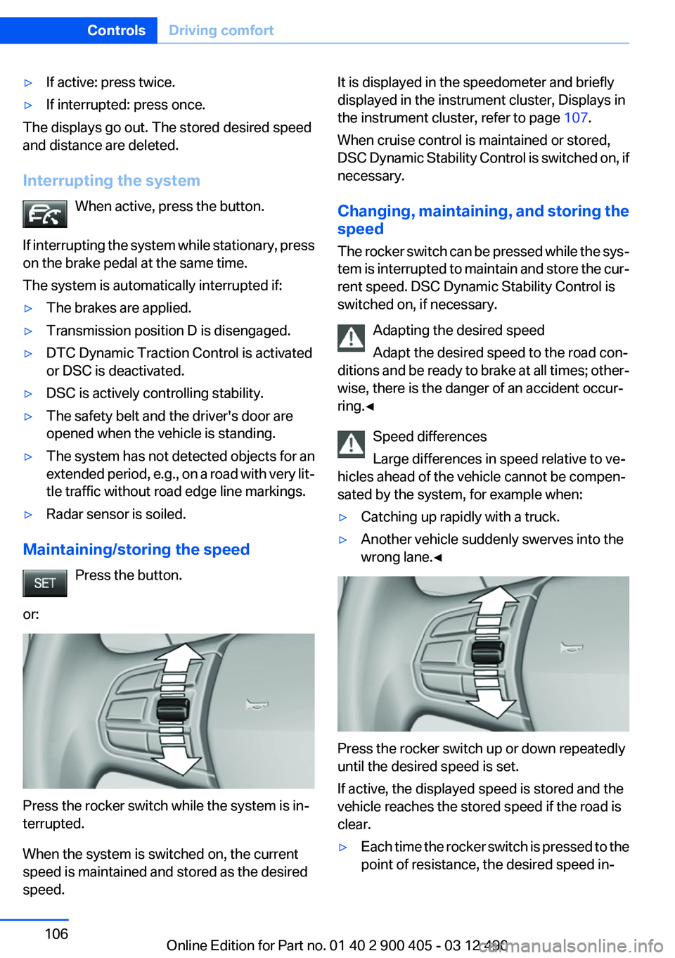
Press the rocker switch while the system is in‐
terrupted.
When the system is switched on, the current
speed is maintained and stored as the desired
speed.
It is displayed in the speedometer and briefly
displayed in the instrument cluster, Displays in
the instrument cluster, refer to page 107.
When cruise control is maintained or stored,
DSC Dynamic Stability Control is switched on, if
necessary.
Changing, maintaining, and storing the
speed
The rocker switch can be pressed while the sys‐
tem is interrupted to maintain and store the cur‐
rent speed. DSC Dynamic Stability Control is
switched on, if necessary.
Adapting the desired speed
Adapt the desired speed to the road con‐
ditions and be ready to brake at all times; other‐
wise, there is the danger of an accident occur‐
ring.◀
Speed differences
Large differences in speed relative to ve‐
hicles ahead of the vehicle cannot be compen‐
sated by the system, for example when:▷Catching up rapidly with a truck.▷Another vehicle suddenly swerves into the
wrong lane.◀
Press the rocker switch up or down repeatedly
until the desired speed is set.
If active, the displayed speed is stored and the
vehicle reaches the stored speed if the road is
clear.
▷Each time the rocker switch is pressed to the
point of resistance, the desired speed in‐Seite 106ControlsDriving comfort106
Online Edition for Part no. 01 40 2 900 405 - 03 12 490
Page 110 of 305
Cornering
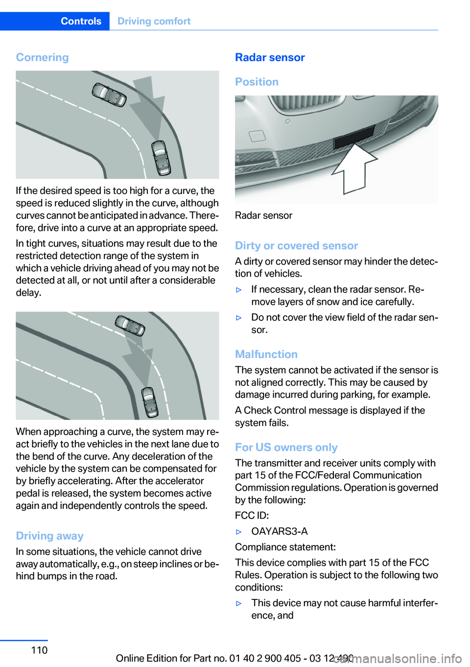
If the desired speed is too high for a curve, the
speed is reduced slightly in the curve, although
curves cannot be anticipated in advance. There‐
fore, drive into a curve at an appropriate speed.
In tight curves, situations may result due to the
restricted detection range of the system in
which a vehicle driving ahead of you may not be
detected at all, or not until after a considerable
delay.
When approaching a curve, the system may re‐
act briefly to the vehicles in the next lane due to
the bend of the curve. Any deceleration of the
vehicle by the system can be compensated for
by briefly accelerating. After the accelerator
pedal is released, the system becomes active
again and independently controls the speed.
Driving away
In some situations, the vehicle cannot drive
away automatically, e.g., on steep inclines or be‐
hind bumps in the road.
Radar sensor
Position
Radar sensor
Dirty or covered sensor
A dirty or covered sensor may hinder the detec‐
tion of vehicles.
▷If necessary, clean the radar sensor. Re‐
move layers of snow and ice carefully.▷Do not cover the view field of the radar sen‐
sor.
Malfunction
The system cannot be activated if the sensor is
not aligned correctly. This may be caused by
damage incurred during parking, for example.
A Check Control message is displayed if the
system fails.
For US owners only
The transmitter and receiver units comply with
part 15 of the FCC/Federal Communication
Commission regulations. Operation is governed
by the following:
FCC ID:
▷OAYARS3-A
Compliance statement:
This device complies with part 15 of the FCC
Rules. Operation is subject to the following two
conditions:
▷This device may not cause harmful interfer‐
ence, andSeite 110ControlsDriving comfort110
Online Edition for Part no. 01 40 2 900 405 - 03 12 490
Page 111 of 305
▷this device must accept any interference re‐
ceived, including interference that may
cause undesired operation.
Any unauthorized modifications or changes to
these devices could void the user's authority to
operate this equipment.
Collision warning with
braking function
The concept
If the vehicle is equipped with Active Cruise
Control with Stop & Go, the collision warning is
controlled via the cruise control radar sensor.
The system issues a two-phase warning of a
danger of collision at speeds above approx.
10 mph/15 km/h. The time of these warnings
may vary depending on the current driving sit‐
uation.
The collision warning is available even if cruise
control has been deactivated.
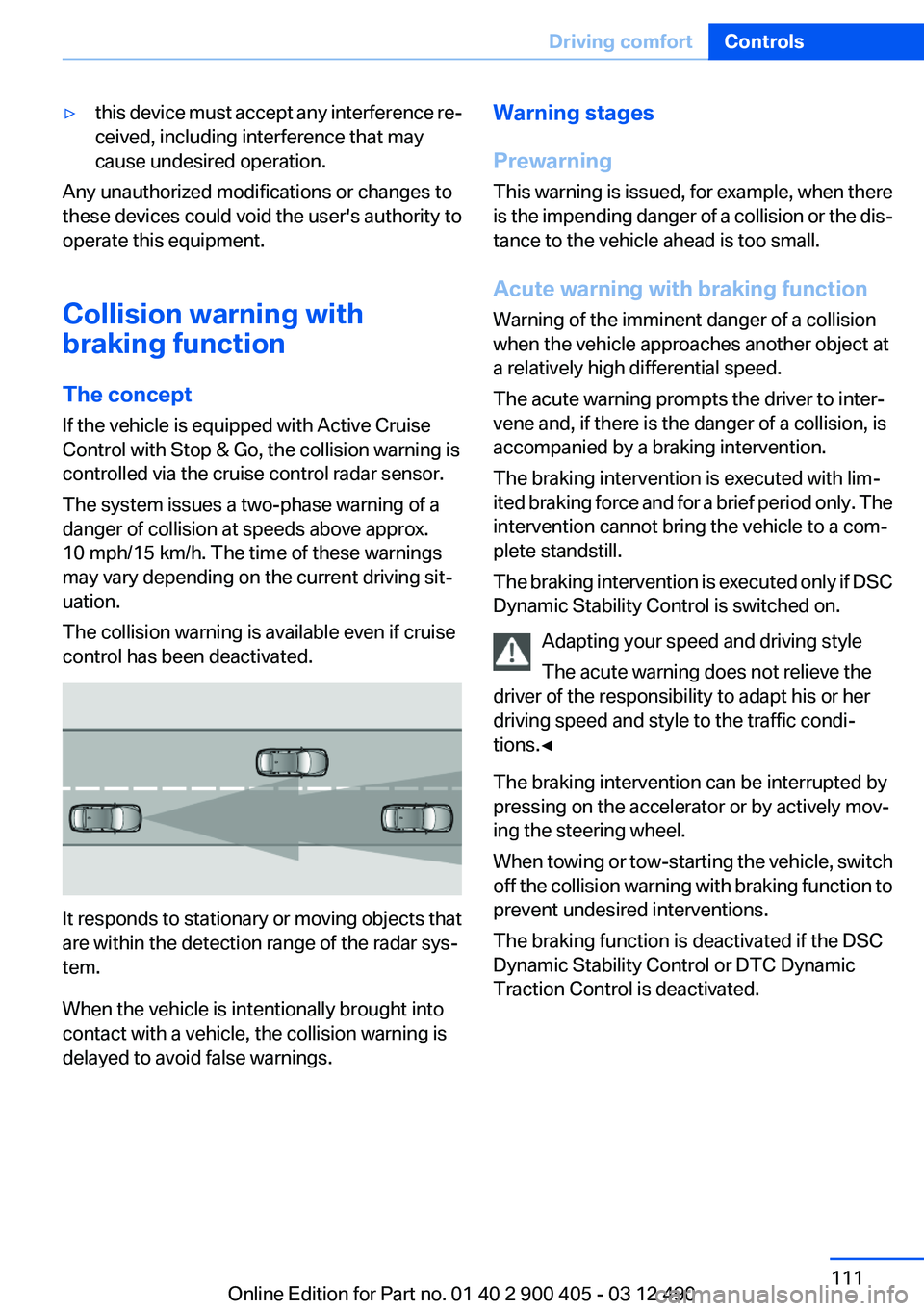
It responds to stationary or moving objects that
are within the detection range of the radar sys‐
tem.
When the vehicle is intentionally brought into
contact with a vehicle, the collision warning is
delayed to avoid false warnings.
Warning stages
Prewarning
This warning is issued, for example, when there
is the impending danger of a collision or the dis‐
tance to the vehicle ahead is too small.
Acute warning with braking function
Warning of the imminent danger of a collision
when the vehicle approaches another object at
a relatively high differential speed.
The acute warning prompts the driver to inter‐
vene and, if there is the danger of a collision, is
accompanied by a braking intervention.
The braking intervention is executed with lim‐
ited braking force and for a brief period only. The
intervention cannot bring the vehicle to a com‐
plete standstill.
The braking intervention is executed only if DSC
Dynamic Stability Control is switched on.
Adapting your speed and driving style
The acute warning does not relieve the
driver of the responsibility to adapt his or her
driving speed and style to the traffic condi‐
tions.◀
The braking intervention can be interrupted by
pressing on the accelerator or by actively mov‐
ing the steering wheel.
When towing or tow-starting the vehicle, switch
off the collision warning with braking function to
prevent undesired interventions.
The braking function is deactivated if the DSC
Dynamic Stability Control or DTC Dynamic
Traction Control is deactivated.Seite 111Driving comfortControls111
Online Edition for Part no. 01 40 2 900 405 - 03 12 490
Page 112 of 305
Switching the warning function on/off
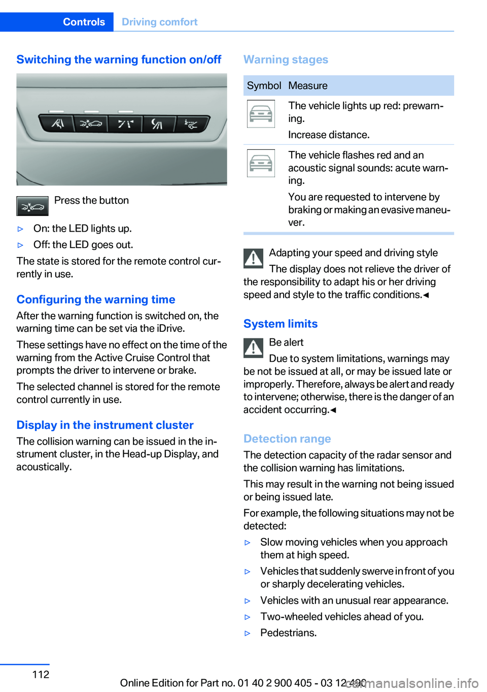
Press the button
▷On: the LED lights up.▷Off: the LED goes out.
The state is stored for the remote control cur‐
rently in use.
Configuring the warning time
After the warning function is switched on, the
warning time can be set via the iDrive.
These settings have no effect on the time of the
warning from the Active Cruise Control that
prompts the driver to intervene or brake.
The selected channel is stored for the remote
control currently in use.
Display in the instrument cluster
The collision warning can be issued in the in‐
strument cluster, in the Head-up Display, and
acoustically.
Warning stagesSymbolMeasureThe vehicle lights up red: prewarn‐
ing.
Increase distance.The vehicle flashes red and an
acoustic signal sounds: acute warn‐
ing.
You are requested to intervene by
braking or making an evasive maneu‐
ver.
Adapting your speed and driving style
The display does not relieve the driver of
the responsibility to adapt his or her driving
speed and style to the traffic conditions.◀
System limits Be alert
Due to system limitations, warnings may
be not be issued at all, or may be issued late or
improperly. Therefore, always be alert and ready
to intervene; otherwise, there is the danger of an
accident occurring.◀
Detection range
The detection capacity of the radar sensor and
the collision warning has limitations.
This may result in the warning not being issued
or being issued late.
For example, the following situations may not be
detected:
▷Slow moving vehicles when you approach
them at high speed.▷Vehicles that suddenly swerve in front of you
or sharply decelerating vehicles.▷Vehicles with an unusual rear appearance.▷Two-wheeled vehicles ahead of you.▷Pedestrians.Seite 112ControlsDriving comfort112
Online Edition for Part no. 01 40 2 900 405 - 03 12 490
Page 113 of 305
Functional limitations
The system may not be fully functional in the
following situations:▷In heavy fog, rain, sprayed water or snowfall.▷In tight curves.▷If the radar sensor is dirty or covered.
Prewarning sensitivity
Depending on the set prewarning time, this may
result in increased false warnings.
Cruise control
The concept
The system is functional at speeds beginning at
approx. 20 mph/30 km/h.
It maintains the speed that was set using the
control elements on the steering wheel.
The system brakes on downhill gradients if en‐
gine braking action is insufficient.
Unfavorable conditions
Do not use the system if unfavorable con‐
ditions make it impossible to drive at a constant
speed, for instance:
▷On curvy roads.▷In heavy traffic.▷On slippery roads, in fog, snow or rain, or on
a loose road surface.
Otherwise, you could lose control of the vehicle
and cause an accident.◀
Controls
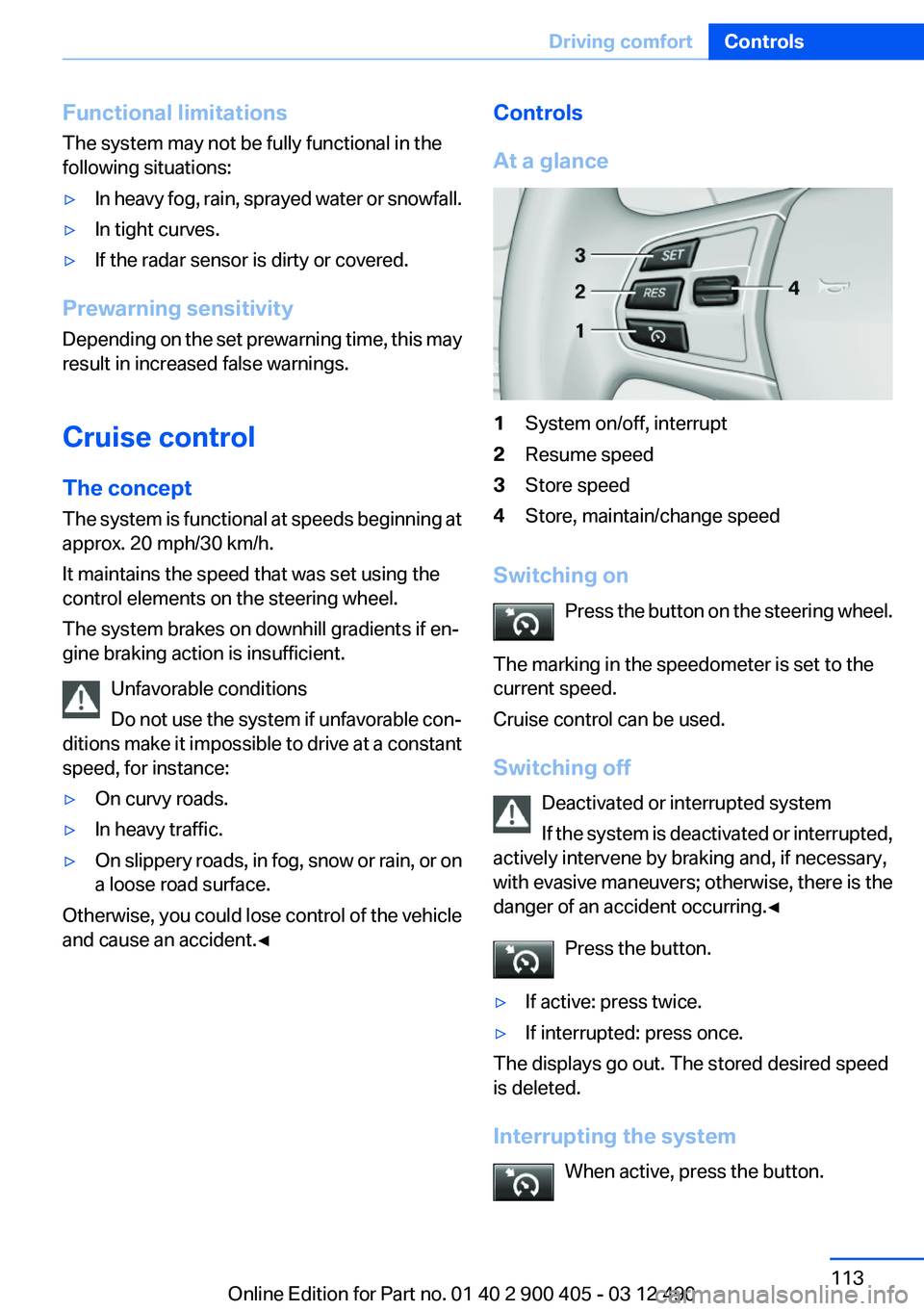
At a glance1System on/off, interrupt2Resume speed3Store speed4Store, maintain/change speed
Switching on Press the button on the steering wheel.
The marking in the speedometer is set to the
current speed.
Cruise control can be used.
Switching off Deactivated or interrupted system
If the system is deactivated or interrupted,
actively intervene by braking and, if necessary,
with evasive maneuvers; otherwise, there is the
danger of an accident occurring.◀
Press the button.
▷If active: press twice.▷If interrupted: press once.
The displays go out. The stored desired speed
is deleted.
Interrupting the system When active, press the button.
Seite 113Driving comfortControls113
Online Edition for Part no. 01 40 2 900 405 - 03 12 490
Page 115 of 305

Desired speed▷The marking lights up in
green: the system is active.▷The marking lights up in or‐
ange: the system has been
interrupted.▷The marking does not light up: the system is
switched off.
Brief status display
Selected desired speed.
If --- appears briefly on the display for Check
Control messages, it is possible that the system
requirements for operation are currently not
met.
PDC Park Distance Control
The concept
In addition to the PDC Park Distance Control, the
backup camera, refer to page 117, can be
switched on.
PDC supports you when parking. Objects that
you are approaching slowly in front of or behind
your vehicle are indicated by:
▷Signal tones.▷Visual display.
Measurement
Measurements are made by ultrasound sensors
in the bumpers.
The range is approx. 6 ft/2 m.
An acoustic warning is first given:
▷By the front sensors and the two rear corner
sensors at approx. 24 in/60 cm.▷By the rear middle sensors at approx.
5 ft/1.50 m.System limits
Check the traffic situation as well
PDC cannot serve as a substitute for the
driver's personal judgment of the traffic situa‐
tion. Check the traffic situation around the vehi‐
cle with your own eyes. Otherwise, an accident
could result from road users or objects located
outside of the PDC detection range.
Loud noises from outside and inside the vehicle
may prevent you from hearing the PDC's signal
tone.◀
Avoid driving quickly with PDC
Avoid approaching an object quickly.
Avoid driving away quickly while PDC is not yet
active.
For technical reasons, the system may other‐
wise be too late in issuing a warning.◀
Limits of ultrasonic measurement
The detection of objects can reach the physical
limits of ultrasonic measurement, e.g.:▷With tow bars and trailer hitches.▷With thin or wedge-shaped objects.▷With low objects.▷With objects with corners and sharp edges.
Low objects already displayed, e.g., curbs, can
move into the blind area of the sensors before or
after a continuous tone sounds.
High, protruding objects such as ledges may not
be detected.
False warnings
PDC may issue a warning under the following
conditions even though there is no obstacle
within the detection range:
▷In heavy rain.▷When sensors are very dirty or covered in
ice.▷When sensors are covered in snow.▷On rough road surfaces.Seite 115Driving comfortControls115
Online Edition for Part no. 01 40 2 900 405 - 03 12 490
Page 117 of 305

▷Forward gear engaged: front area of the ve‐
hicle.▷Reverse gear engaged: rear area of the ve‐
hicle.
Display on the Control Display
Switching on the backup camera via the
iDrive
With PDC activated:
"Rear view camera"
The backup camera image is displayed. The set‐
ting is stored for the remote control currently in
use.
Malfunction
A Check Control message is displayed.
On the Control Display, the areas in front of and
behind the vehicle are shaded. PDC has failed.
Have the system checked.
To ensure full operability:
▷Keep the sensors clean and free of ice.▷When using high-pressure washers, do not
spray the sensors for long periods and main‐
tain a distance of at least 12 in/30 cm.
Surround View
The concept
Surround View includes the following systems:
▷Backup camera, refer to page 117.▷Side View, refer to page 121.▷Top View, refer to page 120.
It assists the driver when parking, maneuvering
and on blind driveways and intersections.
Backup camera
The concept
The backup camera provides assistance in park‐
ing and maneuvering backwards. The area be‐
hind the vehicle is shown on the Control Display.
System limits Check the traffic situation as well
Check the traffic situation around the ve‐
hicle with your own eyes. Otherwise, an accident
could result from road users or objects located
outside the picture area of the backup camera. ◀
Detection of objects
High, protruding objects such as ledges
may not be detected by the backup camera.◀
Switching on automatically
Select transmission position R with the engine
running.
The backup camera image is displayed if the
system was switched on via the iDrive.
Seite 117Driving comfortControls117
Online Edition for Part no. 01 40 2 900 405 - 03 12 490
Page 122 of 305
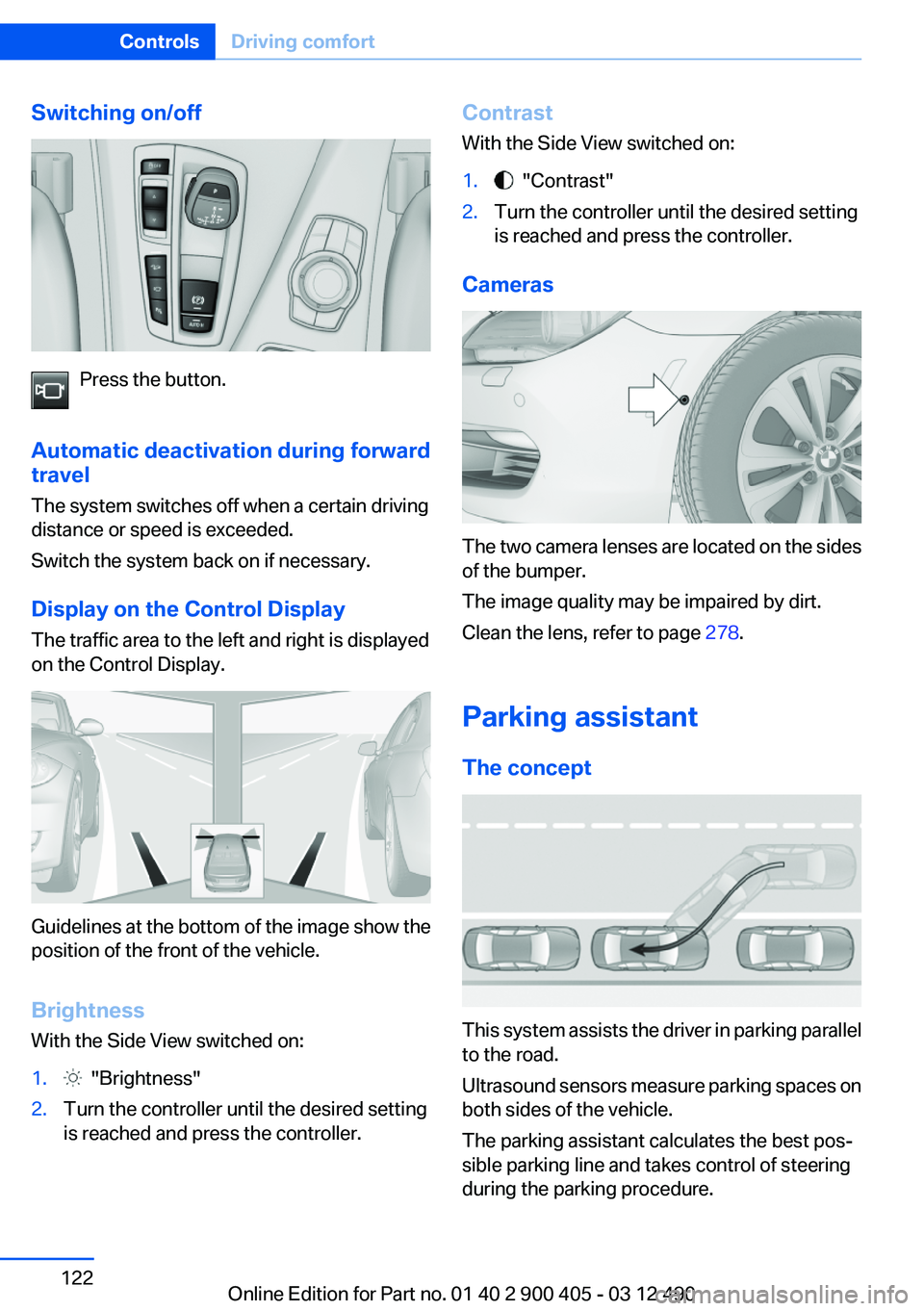
Switching on/off
Press the button.
Automatic deactivation during forward
travel
The system switches off when a certain driving
distance or speed is exceeded.
Switch the system back on if necessary.
Display on the Control Display
The traffic area to the left and right is displayed
on the Control Display.
Guidelines at the bottom of the image show the
position of the front of the vehicle.
Brightness
With the Side View switched on:
1. "Brightness"2.Turn the controller until the desired setting
is reached and press the controller.Contrast
With the Side View switched on:1. "Contrast"2.Turn the controller until the desired setting
is reached and press the controller.
Cameras
The two camera lenses are located on the sides
of the bumper.
The image quality may be impaired by dirt.
Clean the lens, refer to page 278.
Parking assistant
The concept
This system assists the driver in parking parallel
to the road.
Ultrasound sensors measure parking spaces on
both sides of the vehicle.
The parking assistant calculates the best pos‐
sible parking line and takes control of steering
during the parking procedure.
Seite 122ControlsDriving comfort122
Online Edition for Part no. 01 40 2 900 405 - 03 12 490