2013 BMW 640I COUPE steering wheel
[x] Cancel search: steering wheelPage 125 of 232
Radar sensor
For US owners only
The transmitter and receiver units comply with
part 15 of the FCC/Federal Communication
Commission regulations. Operation is governed
by the following:
FCC ID:▷OAYARS3-A
Compliance statement:
This device complies with part 15 of the FCC
Rules. Operation is subject to the following two
conditions:
▷This device may not cause harmful interfer‐
ence, and▷this device must accept any interference re‐
ceived, including interference that may
cause undesired operation.
Any unauthorized modifications or changes to
these devices could void the user's authority to
operate this equipment.
Malfunction
The system cannot be activated if the radar sen‐
sor is not aligned correctly. This may be caused
by damage incurred during parking, for example.
A Check Control message is displayed if the
system fails.
Cruise control
The concept
The system is functional at speeds beginning at
approx. 20 mph/30 km/h.
It maintains the speed that was set using the
control elements on the steering wheel.
The system brakes on downhill gradients if en‐
gine braking action is insufficient.
Unfavorable conditions
Do not use the system if unfavorable con‐
ditions make it impossible to drive at a constant
speed, for instance:▷On curvy roads.▷In heavy traffic.▷On slippery roads, in fog, snow or rain, or on
a loose road surface.
Otherwise, you could lose control of the vehicle
and cause an accident.◀
General information
When ECO PRO is activated, cruise control is
also set to a driving style that saves on fuel con‐
sumption.
Controls
At a glance
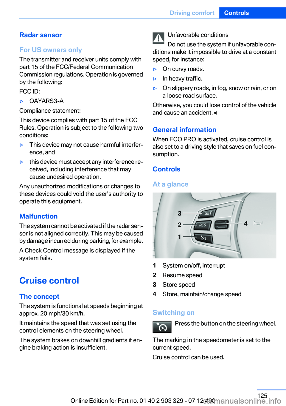
1System on/off, interrupt2Resume speed3Store speed4Store, maintain/change speed
Switching on Press the button on the steering wheel.
The marking in the speedometer is set to the
current speed.
Cruise control can be used.
Seite 125Driving comfortControls125
Online Edition for Part no. 01 40 2 903 329 - 07 12 490
Page 131 of 232
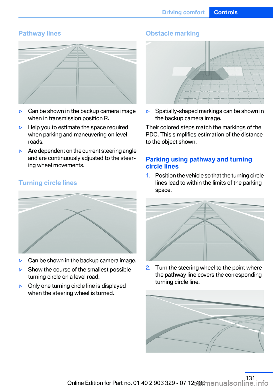
Pathway lines▷Can be shown in the backup camera image
when in transmission position R.▷Help you to estimate the space required
when parking and maneuvering on level
roads.▷Are dependent on the current steering angle
and are continuously adjusted to the steer‐
ing wheel movements.
Turning circle lines
▷Can be shown in the backup camera image.▷Show the course of the smallest possible
turning circle on a level road.▷Only one turning circle line is displayed
when the steering wheel is turned.Obstacle marking▷Spatially-shaped markings can be shown in
the backup camera image.
Their colored steps match the markings of the
PDC. This simplifies estimation of the distance
to the object shown.
Parking using pathway and turning
circle lines
1.Position the vehicle so that the turning circle
lines lead to within the limits of the parking
space.2.Turn the steering wheel to the point where
the pathway line covers the corresponding
turning circle line.Seite 131Driving comfortControls131
Online Edition for Part no. 01 40 2 903 329 - 07 12 490
Page 133 of 232
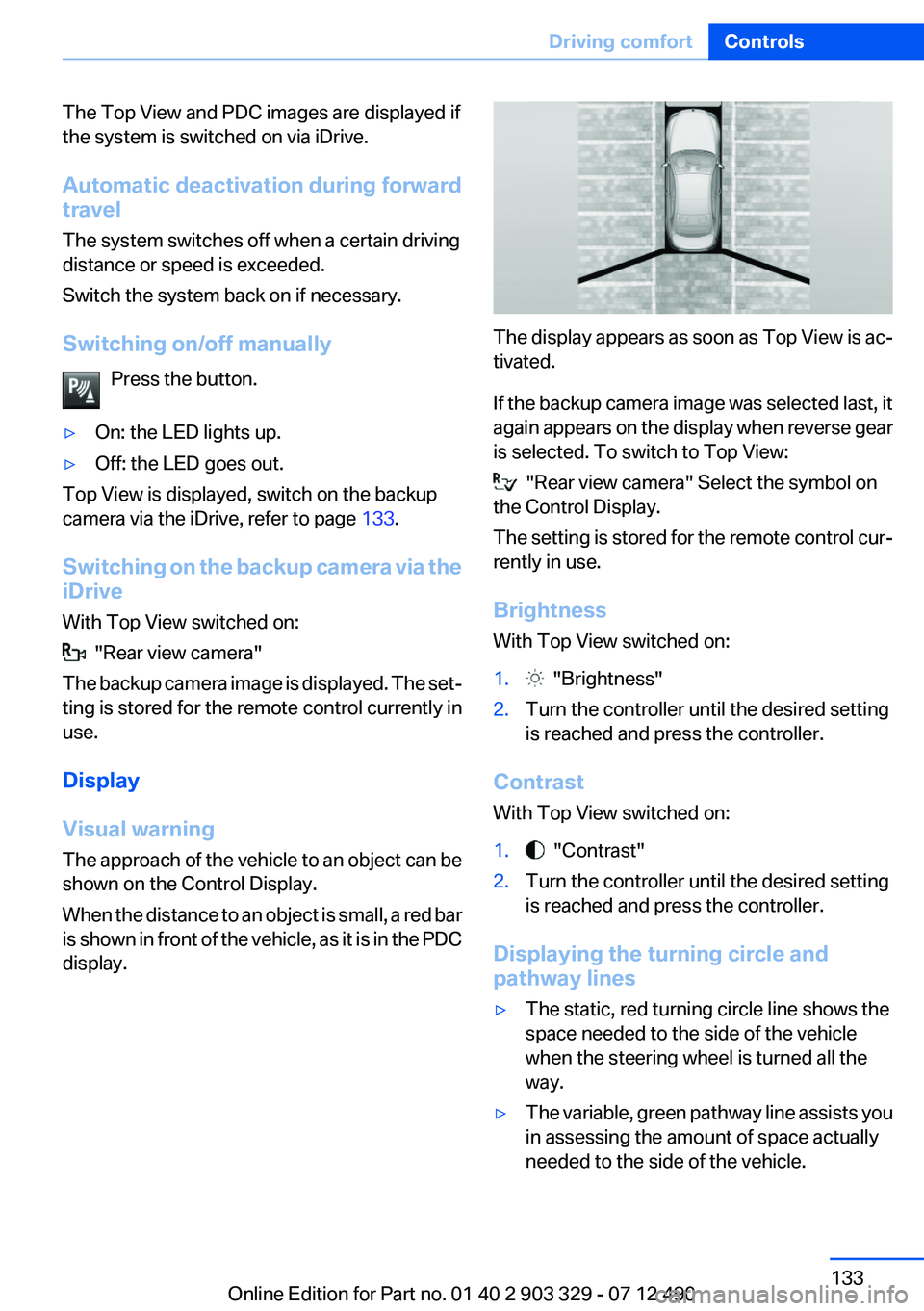
The Top View and PDC images are displayed if
the system is switched on via iDrive.
Automatic deactivation during forward
travel
The system switches off when a certain driving
distance or speed is exceeded.
Switch the system back on if necessary.
Switching on/off manually Press the button.▷On: the LED lights up.▷Off: the LED goes out.
Top View is displayed, switch on the backup
camera via the iDrive, refer to page 133.
Switching on the backup camera via the
iDrive
With Top View switched on:
"Rear view camera"
The backup camera image is displayed. The set‐
ting is stored for the remote control currently in
use.
Display
Visual warning
The approach of the vehicle to an object can be
shown on the Control Display.
When the distance to an object is small, a red bar
is shown in front of the vehicle, as it is in the PDC
display.
The display appears as soon as Top View is ac‐
tivated.
If the backup camera image was selected last, it
again appears on the display when reverse gear
is selected. To switch to Top View:
"Rear view camera" Select the symbol on
the Control Display.
The setting is stored for the remote control cur‐
rently in use.
Brightness
With Top View switched on:
1. "Brightness"2.Turn the controller until the desired setting
is reached and press the controller.
Contrast
With Top View switched on:
1. "Contrast"2.Turn the controller until the desired setting
is reached and press the controller.
Displaying the turning circle and
pathway lines
▷The static, red turning circle line shows the
space needed to the side of the vehicle
when the steering wheel is turned all the
way.▷The variable, green pathway line assists you
in assessing the amount of space actually
needed to the side of the vehicle.Seite 133Driving comfortControls133
Online Edition for Part no. 01 40 2 903 329 - 07 12 490
Page 134 of 232
The pathway line is dependent on the cur‐
rent steering angle and is continuously ad‐
justed with the steering wheel movement.
"Parking aid lines"
Turning circle and pathway lines are displayed.
System limits
Top View cannot be used in the following situa‐
tions:
▷With a door open.▷With the trunk lid open.▷With an exterior mirror folded in.▷In poor light.
A Check Control message is displayed in some
of these situations.
Side View
The concept
Side View provides an early look at cross traffic
at blind driveways and intersections. Road users
concealed by obstacles to the left and right of
the vehicle can only be detected relatively late
from the driver's seat. To improve visibility, two
cameras in the front of the vehicle record the
traffic situation on each side.
Notes
The images from both cameras are shown si‐
multaneously on the Control Display.
Check the traffic situation as well
Check the traffic situation around the ve‐
hicle on blind driveways and intersections with
your own eyes. Otherwise, an accident could re‐
sult from road users or objects located outside
the picture area of the Side View cameras.◀
At a glance
Button in the vehicle
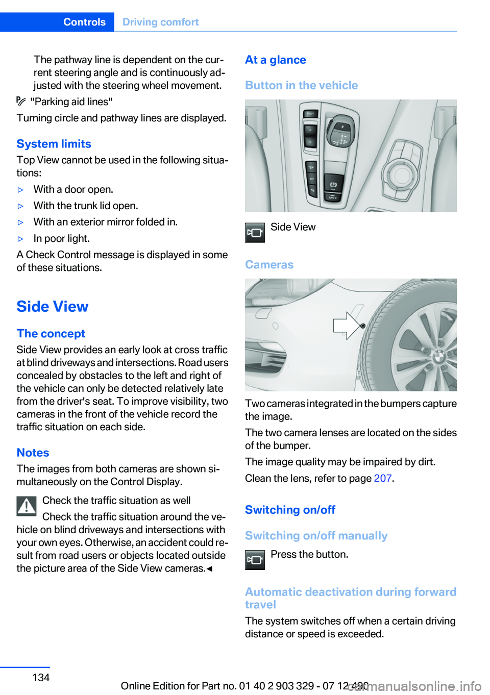
Side View
Cameras
Two cameras integrated in the bumpers capture
the image.
The two camera lenses are located on the sides
of the bumper.
The image quality may be impaired by dirt.
Clean the lens, refer to page 207.
Switching on/off
Switching on/off manually Press the button.
Automatic deactivation during forward
travel
The system switches off when a certain driving
distance or speed is exceeded.
Seite 134ControlsDriving comfort134
Online Edition for Part no. 01 40 2 903 329 - 07 12 490
Page 137 of 232
Switching on with reverse gear
Shift into reverse.
The current status of the parking space search
is indicated on the Control Display.
Activate:
"Parking Assistant" Select the
symbol in the Control Display.
Switching off
The system can be deactivated as follows:
▷Press the button.▷Switch off the ignition.
Display on the Control Display
Activating/deactivating the system
SymbolMeaning Gray: the system is not available.
White: the system is available but not
activated. The system is activated.
System status
The status is displayed with symbols.
Gray: parking space search.
Blue: the system is activated. A
suitable parking space was
found.
The parking procedure is active.
Steering control has been seized.
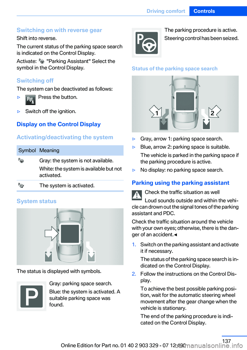
Status of the parking space search▷Gray, arrow 1: parking space search.▷Blue, arrow 2: parking space is suitable.
The vehicle is parked in the parking space if
the parking procedure is active.▷No display: no parking space search.
Parking using the parking assistant
Check the traffic situation as well
Loud sounds outside and within the vehi‐
cle can drown out the signal tones of the parking
assistant and PDC.
Check the traffic situation around the vehicle
with your own eyes; otherwise, there is the dan‐
ger of an accident.◀
1.Switch on the parking assistant and activate
it if necessary.
The status of the parking space search is in‐
dicated on the Control Display.2.Follow the instructions on the Control Dis‐
play.
To achieve the best possible parking posi‐
tion, wait for the automatic steering wheel
movement after the gear change when the
vehicle is stationary.
The end of the parking procedure is indi‐
cated on the Control Display.Seite 137Driving comfortControls137
Online Edition for Part no. 01 40 2 903 329 - 07 12 490
Page 138 of 232
3.Adjust the parking position yourself if nec‐
essary.
Interrupting manually
The parking assistant can be interrupted at any
time:
▷ " Parking Assistant" Select the symbol on
the Control Display.▷Press the button.
Interrupting automatically
The system is interrupted automatically in the
following situations:
▷If the driver grasps the steering wheel or if
he takes over steering.▷If a gear is selected that does not match the
instruction on the Control Display.▷If a turn signal is activated in the opposite
direction to the desired side for parking.▷If the vehicle speed exceeds approx.
6 mph/10 km/h.▷On snow-covered or slippery road surfaces
if necessary.▷If doors are open.▷If the Park Distance Control PDC displays
clearances that are too small.▷If a maximum number of parking attempts or
the time taken for parking is exceeded.
A Check Control message is displayed.
Continuing
An interrupted parking procedure can be con‐
tinued if necessary.
Follow the instructions on the Control Display to
do this.
System limits
No parking assistance
The parking assistant does not offer assistance
in the following situations:
▷In tight curves.
Functional limitations
The system may not be fully functional in the
following situations:
▷When sensors are dirty or iced over.▷In heavy fog, rain or snowfall.▷On bumpy road surfaces such as gravel
roads.▷When leaves or snow has collected in the
parking space.
Limits of ultrasonic measurement
The detection of objects can reach the physical
limits of ultrasonic measurement, e.g. in the fol‐
lowing circumstances:
▷With tow bars and trailer hitches.▷With thin or wedge-shaped objects.▷With elevated, protruding objects such as
ledges or cargo.▷With objects with corners and sharp edges.▷With objects with a fine surface structure,
such as fences.
Low objects already displayed, e.g., curbs, can
move into the blind area of the sensors before or
after a continuous tone sounds.
High, protruding objects such as ledges may not
be detected.
The parking assistant may identify parking
spaces that are not suitable for parking.
Malfunction
A Check Control message is displayed.
The parking assistant failed. Have the system
checked.
Seite 138ControlsDriving comfort138
Online Edition for Part no. 01 40 2 903 329 - 07 12 490
Page 182 of 232

Consult your service center for more informa‐
tion.
Use
Use only in pairs on the rear wheels, equipped
with the tires of the following size:▷225/55 R 17.▷245/45 R 18.▷245/40 R 19
Follow the chain manufacturer's instructions.
Make sure that the snow chains are always suf‐
ficiently tight. Retighten as needed according to
the chain manufacturer's instructions.
Do not initialize the Flat Tire Monitor after
mounting snow chains, as doing so may result
in incorrect readings.
Do not initialize the Tire Pressure Monitor after
mounting snow chains, as doing so may result
in incorrect readings.
When driving with snow chains, briefly activate
Dynamic Traction Control if necessary.
Maximum speed with snow chains
Do not exceed a speed of 30 mph/50 km/h when
using snow chains.
Snow chain detection
The concept
When using snow chains, you should set
whether you are driving with or without snow
chains via the iDrive.
The snow chain detection system supports you
by automatically showing the detected state on
the Control Display.
When snow chains are in use, the rear axle steer‐
ing of the Integral Active Steering is deactivated
automatically.
At speeds above the maximum permitted speed
with snow chains of 30 mph/50 km/h, the rear
axle steering is activated again automatically.
Activating the status1."Settings"2."Tire chains"3."Tire chains installed"
Automatic detection
If functioning properly:
▷Snow chains are mounted. The setting is not
activated
.
After you drive a short distance, a Check
Control message is shown and the state is
activated automatically.
Confirm the automatic activation.
▷Snow chains are not mounted. The setting
is activated
.
At speeds above 30 mph/50 km/h, a Check
Control message is displayed. Deactivate
the status manually.
If not functioning properly:
▷Snow chains are mounted. The setting is not
activated
.
A Check Control message is not displayed.
The automatic detection system is malfunc‐
tioning. Activate the status manually.
Activating/deactivating rear axle
steering
If the status indicating that snow chains are in
use is activated, the rear axle steering is deacti‐
vated automatically.
At speeds above 30 mph/50 km/h, the rear axle
steering is activated again, even though snow
chains are in use.
Seite 182MobilityWheels and tires182
Online Edition for Part no. 01 40 2 903 329 - 07 12 490
Page 196 of 232
Vehicle battery
Maintenance
The battery is maintenance-free, i.e., the elec‐
trolyte will last for the life of the battery.
Your service center will be glad to advise you on
questions regarding the battery.
Battery replacement Use approved vehicle batteries only
Only use vehicle batteries that have been
approved for your vehicle by the manufacturer;
otherwise, the vehicle could be damaged and
systems or functions may not be fully availa‐
ble.◀
After a battery replacement, have the battery
registered on the vehicle by your service center
to ensure that all comfort functions are fully
available and that any Check Control messages
are no longer displayed.
Charging the battery
Note Do not plug the charger into the socket
Do not connect battery chargers to the
factory-installed sockets in the vehicle. Doing so
may result in damage to the vehicle.◀
Starting aid terminals
In the vehicle, only charge the battery via the
starting aid terminals, refer to page 200, in the
engine compartment with the engine off.
Power failure
After a temporary power loss, some equipment
needs to be reinitialized.
Individual settings need to be reprogrammed:▷Seat, mirror, and steering wheel memory:
store the positions again.▷Time: update.▷Date: update.▷Radio station: save again.▷Navigation system: wait for the operability of
the navigation.
Disposing of old batteries
Have old batteries disposed of by your
service center or bring them to a recy‐
cling center.
Maintain the battery in an upright position for
transport and storage. Secure the battery so
that it does not tip over during transport.
Fuses
Notes Replacing fuses
Never attempt to repair a blown fuse and
do not replace a defective fuse with a substitute
of another color or amperage rating; this could
lead to a circuit overload, ultimately resulting in
a fire in the vehicle.◀
Plastic tweezers and information on the fuse
types and locations are stored in the fuse box in
the cargo area.
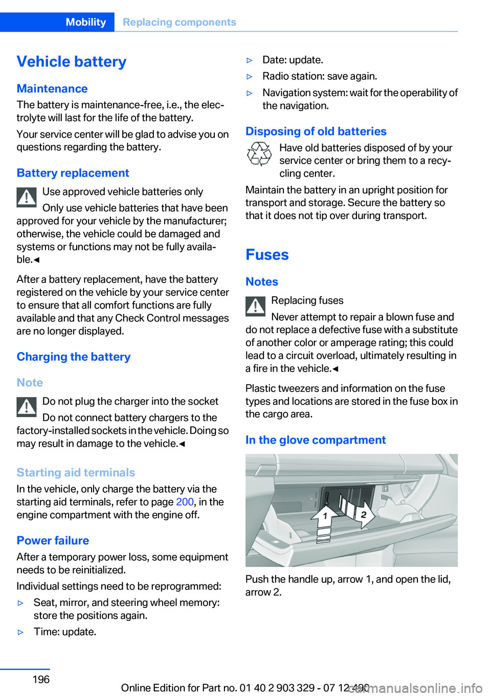
In the glove compartment
Push the handle up, arrow 1, and open the lid,
arrow 2.
Seite 196MobilityReplacing components196
Online Edition for Part no. 01 40 2 903 329 - 07 12 490