2013 BMW 640I COUPE fog light
[x] Cancel search: fog lightPage 108 of 232

Camera
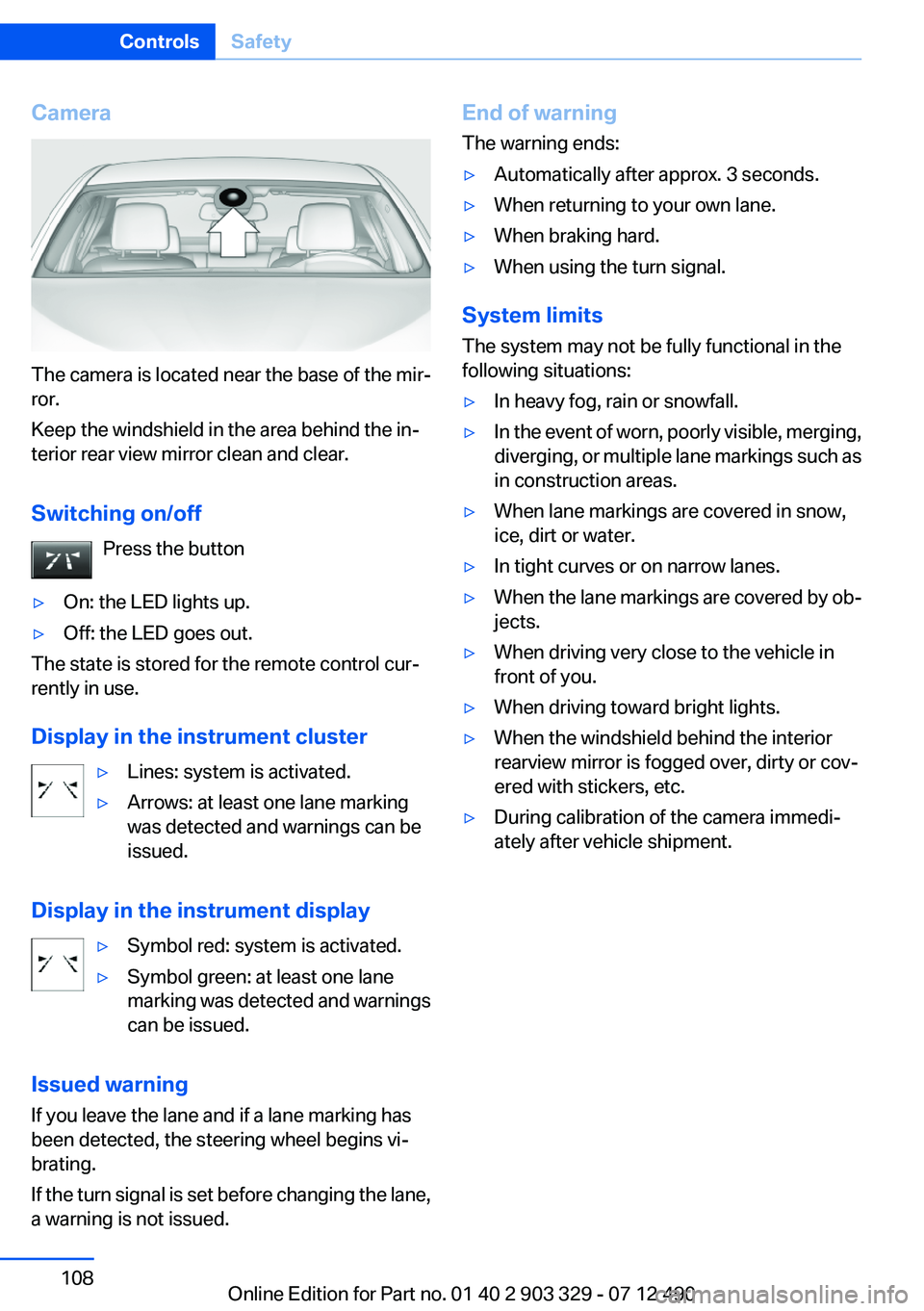
The camera is located near the base of the mir‐
ror.
Keep the windshield in the area behind the in‐
terior rear view mirror clean and clear.
Switching on/off Press the button
▷On: the LED lights up.▷Off: the LED goes out.
The state is stored for the remote control cur‐
rently in use.
Display in the instrument cluster
▷Lines: system is activated.▷Arrows: at least one lane marking
was detected and warnings can be
issued.
Display in the instrument display
▷Symbol red: system is activated.▷Symbol green: at least one lane
marking was detected and warnings
can be issued.
Issued warning
If you leave the lane and if a lane marking has
been detected, the steering wheel begins vi‐
brating.
If the turn signal is set before changing the lane,
a warning is not issued.
End of warning
The warning ends:▷Automatically after approx. 3 seconds.▷When returning to your own lane.▷When braking hard.▷When using the turn signal.
System limits
The system may not be fully functional in the
following situations:
▷In heavy fog, rain or snowfall.▷In the event of worn, poorly visible, merging,
diverging, or multiple lane markings such as
in construction areas.▷When lane markings are covered in snow,
ice, dirt or water.▷In tight curves or on narrow lanes.▷When the lane markings are covered by ob‐
jects.▷When driving very close to the vehicle in
front of you.▷When driving toward bright lights.▷When the windshield behind the interior
rearview mirror is fogged over, dirty or cov‐
ered with stickers, etc.▷During calibration of the camera immedi‐
ately after vehicle shipment.Seite 108ControlsSafety108
Online Edition for Part no. 01 40 2 903 329 - 07 12 490
Page 110 of 232

Display
Information stage
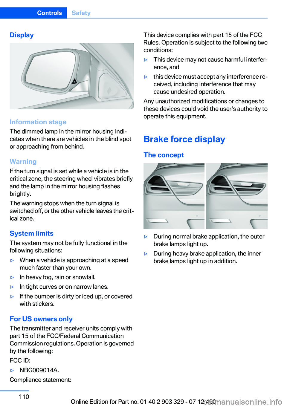
The dimmed lamp in the mirror housing indi‐
cates when there are vehicles in the blind spot
or approaching from behind.
Warning
If the turn signal is set while a vehicle is in the
critical zone, the steering wheel vibrates briefly
and the lamp in the mirror housing flashes
brightly.
The warning stops when the turn signal is
switched off, or the other vehicle leaves the crit‐
ical zone.
System limits
The system may not be fully functional in the
following situations:
▷When a vehicle is approaching at a speed
much faster than your own.▷In heavy fog, rain or snowfall.▷In tight curves or on narrow lanes.▷If the bumper is dirty or iced up, or covered
with stickers.
For US owners only
The transmitter and receiver units comply with
part 15 of the FCC/Federal Communication
Commission regulations. Operation is governed
by the following:
FCC ID:
▷NBG009014A.
Compliance statement:
This device complies with part 15 of the FCC
Rules. Operation is subject to the following two
conditions:▷This device may not cause harmful interfer‐
ence, and▷this device must accept any interference re‐
ceived, including interference that may
cause undesired operation.
Any unauthorized modifications or changes to
these devices could void the user's authority to
operate this equipment.
Brake force display
The concept
▷During normal brake application, the outer
brake lamps light up.▷During heavy brake application, the inner
brake lamps light up in addition.Seite 110ControlsSafety110
Online Edition for Part no. 01 40 2 903 329 - 07 12 490
Page 193 of 232

Danger of burns
Only change bulbs when they are cool;
otherwise, there is the danger of getting
burned.◀
Working on the lighting system
When working on the lighting system, you
should always switch off the lights affected to
prevent short circuits.
To avoid possible injury or equipment damage
when replacing bulbs, observe any instructions
provided by the bulb manufacturer.◀
Do not perform work/bulb replacement on
xenon headlamps
Have any work on the xenon lighting system, in‐
cluding bulb replacement, performed only by a
service center. Due to the high voltage present
in the system, there is the danger of fatal injuries
if work is carried out improperly.◀
Do not touch the bulbs
Do not touch the glass of new bulbs with
your bare hands, as even minute amounts of
contamination will burn into the bulb's surface
and reduce its service life.
Use a clean tissue, cloth or something similar, or
hold the bulb by its base.◀
Light-emitting diodes (LEDs)
Light-emitting diodes installed behind a cover
serve as the light source for controls, display el‐
ements and other equipment.
These light-emitting diodes, which are related
to conventional lasers, are officially designated
as Class 1 light-emitting diodes.
Do not remove the covers
Do not remove the covers, and never stare
into the unfiltered light for several hours; other‐
wise, irritation of the retina could result.◀Headlamp glass
Condensation can form on the inside of the ex‐
ternal lamps in cool or humid weather. When
driving with the light switched on, the conden‐
sation evaporates after a short time. The head‐
lamp glasses do not need to be changed.
If the headlamps do not dim despite driving with
the light switched on, increasing humidity forms,
e. g. water droplets in the light, have the service
center check this.
Xenon headlamps
Notes
Because of the long life of these bulbs, the like‐
lihood of failure is very low. Switching the lamps
on and off frequently shortens their life.
If a xenon bulb fails, switch on the front fog lamps
and continue the trip with great care. Comply
with local regulations.
Do not perform work/bulb replacement on
xenon headlamps
Have any work on the xenon lighting system, in‐
cluding bulb replacement, performed only by a
service center. Due to the high voltage present
in the system, there is the danger of fatal injuries
if work is carried out improperly.◀
For checking and adjusting headlamp aim,
please contact your BMW center.
Light-emitting diodes (LEDs)
Follow the general instructions on lamps and
bulbs, refer to page 192.
With Xenon-headlamps, the following lamps are
designed with LED technology:▷Parking lamps and roadside parking lamps▷Turn signals, incl. side indicators▷Front fog lamps▷Daytime running lights
Contact your service center in the event of a
malfunction.
Seite 193Replacing componentsMobility193
Online Edition for Part no. 01 40 2 903 329 - 07 12 490
Page 194 of 232

Turning lamp on the Xenon headlamp
Follow the general instructions on lamps and
bulbs, refer to page 192.
The illustration shows the left side of the engine
compartment.
55-watt bulb, H31.Turn the cap and remove it.2.Detach the wire bracket.3.Disconnect the cable at the plug-in connec‐
tion and remove the bulb.4.Insert the new bulb. Ensure that the bulb has
the correct orientation. Because of its
shape, the bulb can only be inserted in one
direction.5.Secure the bulb with the wire bracket.6.Connect the bulb.7.Mount the cap.
LED headlamps
Light-emitting diodes (LEDs)
Follow the general instructions on lamps and
bulbs, refer to page 192.
With LED headlamps, all front lamps and side
indicators are designed with LED technology.
If and LED fails, switch on the front fog lamps
and continue the trip with great care. Comply
with local regulations.
Contact your service center in the event of a
malfunction.
Tail lamps, bulb replacement
At a glance1Turn signal/brake lamp2Reversing lamp3Inside brake lamp4Tail lamp5Outside brake lamp6Rear reflector
Turn signal, outer brake, tail, and
license plate lamps
Follow the general instructions on lamps and
bulbs, refer to page 192.
These lights feature LED technology.
Contact your service center in the event of a
malfunction.
Seite 194MobilityReplacing components194
Online Edition for Part no. 01 40 2 903 329 - 07 12 490
Page 225 of 232

Fault displays, refer to CheckControl 74
Filler neck for engine oil 186
Fine wood, care 206
First aid kit 199
Fitting for towing, refer to Tow fitting 202
Flat tire, changing wheels 195
Flat Tire Monitor FTM 98
Flat tire, Tire Pressure Monitor TPM 95
Flat tire, warning lamp 96, 99
Flooding 159
Floor carpet, care 206
Floor mats, care 206
Fold-out position, windshield wipers 66
Foot brake 159
For the headliner, refer to All around the interior rearview
mirror 15
Front airbags 92
Front center armrest 152
Front fog lamps 90
Front lamps 0
Front passenger airbags, au‐ tomatic deactivation 94
Front passenger airbags, indi‐ cator lamp 94
Front seats 45
Front turn signals, refer to Light-emitting diodes,
LEDs 193
FTM Flat Tire Monitor 98
Fuel cap 170
Fuel consumption, current 78
Fuel consumption, refer to Average fuel consump‐
tion 82
Fuel filler flap 170
Fuel gauge 77
Fuel quality 172
Fuel, tank capacity 212
Fuse 196 G
Garage door opener, refer to Integrated universal remote
control 146
Gasoline 172
Gasoline quality 172
Gear change, automatic trans‐ mission 67
Gear shift indicator 79
General driving notes 158
Glass sunroof, powered with tilt function 43
Glove compartment 151
Gross vehicle weight, ap‐ proved 211
H
Handbrake, refer to Parking brake 61
Hand-held transmitter, alter‐ nating code 147
Hazard warning flashers 198
HDC Hill Descent Control 113
Head airbags 92
Headlamp control, auto‐ matic 88
Headlamp courtesy delay fea‐ ture 88
Headlamp courtesy delay fea‐ ture via remote control 35
Headlamp flasher 64
Headlamp glass 193
Headlamps 0
Headlamps, care 205
Headlamp washer system 64
Head restraints 45
Head restraints, front 49
Head-Up Display 139
Head-up Display, care 207
Heavy cargo, stowing 162
Height, seats 45
Height, vehicle 210
High-beam Assistant 89
High beams 64 High beams/low beams, refer
to High-beam Assistant 89
Hill Descent Control HDC 113
Hills 160
Hill start assistant, refer to Drive-off assistant 111
Hints 6
Holder for beverages 153
Homepage 6
Hood 183
Horn 12
Hotel function, trunk lid 38
Hot exhaust system 159
HUD Head-Up Display 139
Hydroplaning 159
I
Ice warning, refer to External temperature warning 77
Icy roads, refer to External temperature warning 77
Identification marks, tires 178
Identification number, refer to Important features in the en‐
gine compartment 183
iDrive 16
Ignition key, refer to Remote control 30
Ignition off 57
Ignition on 57
Indication of a flat tire 96, 99
Individual air distribution 142
Individual settings, refer to Personal Profile 31
Inflation pressure, tires 173
Inflation pressure warning FTM, tires 98
Info display, refer to Com‐ puter 81
Initialization, Integral Active Steering 115
Initialize, Tire Pressure Moni‐ tor TPM 96
Initializing, Flat Tire Monitor FTM 99 Seite 225Everything from A to ZReference225
Online Edition for Part no. 01 40 2 903 329 - 07 12 490