2013 BMW 640I CONVERTIBLE reset
[x] Cancel search: resetPage 32 of 240

Profile management
Opening the profiles
A different profile can be called up than the one
associated with the remote control currently in
use.1."Settings"2."Profiles"3.Select a profile.
The profile that is opened is assigned to the re‐
mote control currently in use.
Renaming profiles
1."Settings"2."Profiles"
The current profile is selected.3.Open "Options".4."Rename current profile"Resetting profiles
The settings of the active profile are reset to
their default values.1.Switch on the ignition.2."Settings"3."Profiles"
The current profile is selected.4.Open "Options".5."Reset current profile"
Importing profiles
Existing settings and contacts are overwritten
with the imported profile.
1."Settings"2."Profiles"3."Import profile"4.USB interface, refer to page 158: "USB
device"
Exporting profiles
Most settings of the active profile and the saved
contacts can be exported.
This can be useful for storing and opening per‐
sonal settings, e.g. if settings are accidentally
changed or deleted.
1."Settings"2."Profiles"3."Export profile"4.USB interface, refer to page 158: "USB
device"Seite 32ControlsOpening and closing32
Online Edition for Part no. 01 40 2 903 169 - 07 12 490
Page 76 of 240

DisplaysVehicle equipment
All standard, country-specific and optional
equipment that is offered in the model series is
described in this chapter. Therefore, equipmentis also described that is not available in a vehicle,
e. g., because of the selected optional equip‐
ment or country variant. This also applies for
safety-related functions and systems.
Instrument cluster
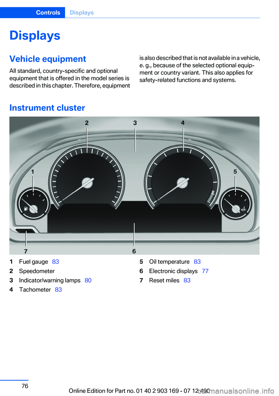
1Fuel gauge 832Speedometer3Indicator/warning lamps 804Tachometer 835Oil temperature 836Electronic displays 777Reset miles 83Seite 76ControlsDisplays76
Online Edition for Part no. 01 40 2 903 169 - 07 12 490
Page 78 of 240

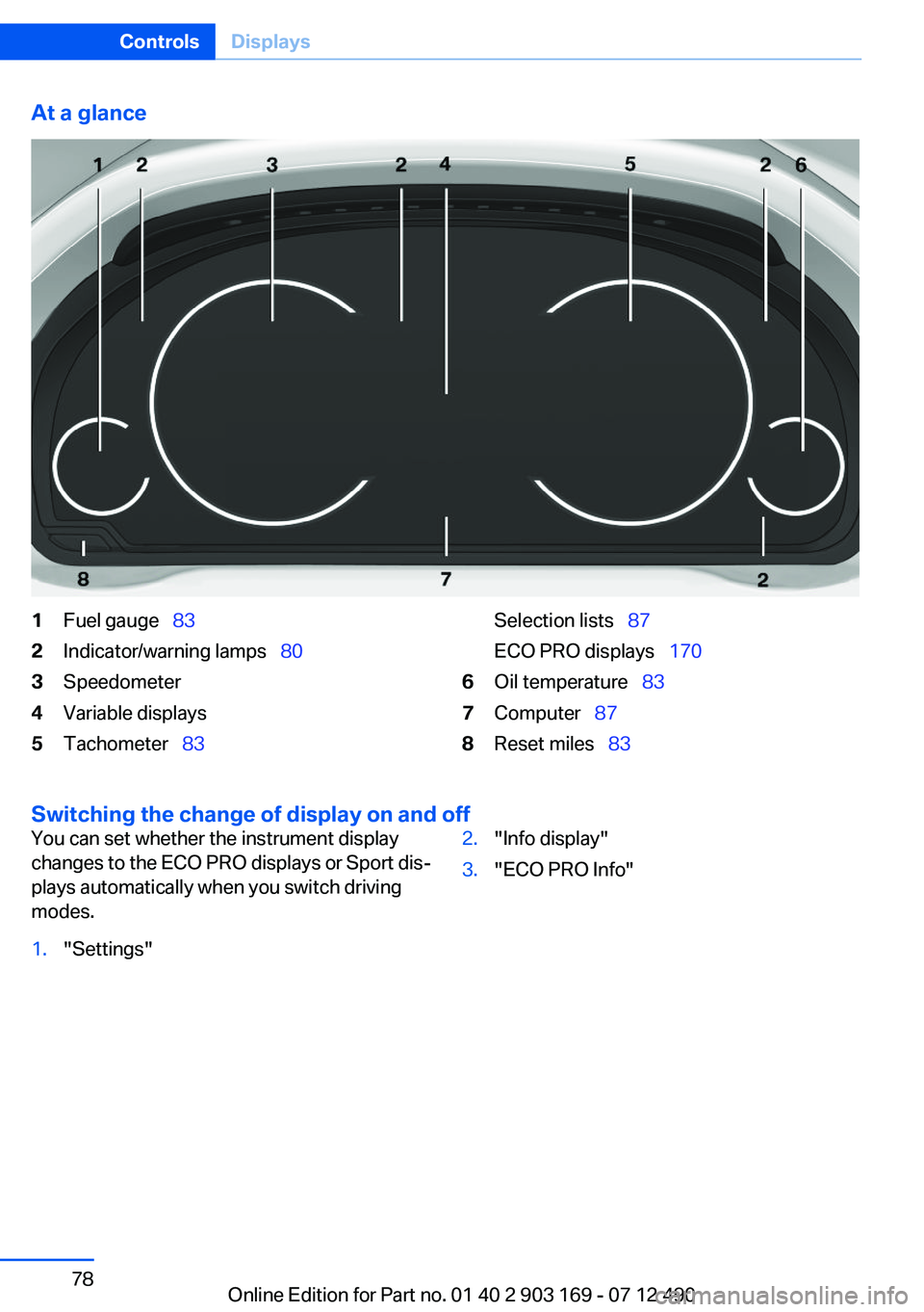
At a glance1Fuel gauge 832Indicator/warning lamps 803Speedometer4Variable displays5Tachometer 83Selection lists 87
ECO PRO displays 1706Oil temperature 837Computer 878Reset miles 83
Switching the change of display on and off
You can set whether the instrument display
changes to the ECO PRO displays or Sport dis‐
plays automatically when you switch driving
modes.1."Settings"2."Info display"3."ECO PRO Info"Seite 78ControlsDisplays78
Online Edition for Part no. 01 40 2 903 169 - 07 12 490
Page 83 of 240

Fuel gaugeThe vehicle inclination may
cause the display to vary.
Notes on refueling, refer to
page 176.
Tachometer
Always avoid engine speeds in the red warning
field. In this range, the fuel supply is interrupted
to protect the engine.
Engine oil temperature▷Cold engine: the pointer is at
the low temperature end.
Drive at moderate engine and
vehicle speeds.▷Normal operating tempera‐
ture: the pointer is in the mid‐
dle or in the left half of the
temperature display.▷Hot engine: the pointer is at the high tem‐
perature end. A Check Control message is
displayed in addition.
Coolant temperature
If the coolant along with the engine becomes too
hot, a Check Control message is displayed.
Check the coolant level, refer to page 194.
Odometer and trip odometer
▷Odometer, arrow 1.▷Trip odometer, arrow 2.Display/reset miles Press the knob.▷When the ignition is switched
off, the time, external temper‐
ature and odometer are dis‐
played.▷When the ignition is switched on, the trip
odometer is reset.
External temperature
External temperature warning If the indicator drops to
+37 ℉/+3 ℃, a signal sounds.
A Check Control message is dis‐
played.
There is an increased risk of ice
on roads.
Ice on roads
Even at temperatures above +37 ℉/+3 ℃,
there can be a risk of ice on roads.
Therefore, drive carefully on bridges and shaded
roads, for example, to avoid the increased risk of
an accident.◀
Time The time is displayed at the bot‐
tom of the instrument cluster.
Setting the time and time format,
refer to page 90.
Date The date is displayed in the in‐
strument cluster.
Setting the date and date format,
refer to page 90.
Seite 83DisplaysControls83
Online Edition for Part no. 01 40 2 903 169 - 07 12 490
Page 88 of 240

Calling up information on the info
display
Press the onboard computer button on the turn
signal lever.
Information is displayed on the info display of the
instrument cluster.
Information at a glance
Repeatedly pressing the button on the turn sig‐
nal lever calls up the following information on the
info display:
▷Range.▷Average fuel consumption.▷Average speed.▷Date.▷Speed limit detection.▷Time of arrival.
When destination guidance is activated in
the navigation system.▷Distance to destination.
When destination guidance is activated in
the navigation system.▷Arrow view of navigation system.
When destination guidance is activated in
the navigation system.
When the arrow view in the Head-up Display
is inactive.▷ECO PRO bonus range.Adjusting the info display
You can select what information from the on‐
board computer is to be displayed on the info
display of the instrument cluster.1."Settings"2."Info display"3.Select the desired displays.
Information in detail
Range
Displays the estimated cruising range available
with the remaining fuel.
It is calculated based on your driving style over
the last 20 miles/30 km. If there is only enough
fuel left for less than 45 miles/80 km, the color
of the display changes.
Average fuel consumption
This is calculated for the period during which the
engine is running.
The average fuel consumption is calculated on
the basis of various distances.
Average speed
Periods in which the vehicle is parked with the
engine manually stopped do not enter into the
calculation of the average speed.
Resetting average values
Press and hold the computer button on the turn
signal lever.
Distance to destination
The distance remaining to the destination is dis‐
played if a destination is entered in the naviga‐
tion system before the trip is started.
The distance to the destination is adopted au‐
tomatically.
Seite 88ControlsDisplays88
Online Edition for Part no. 01 40 2 903 169 - 07 12 490
Page 89 of 240

Time of arrivalThe estimated time of arrival is
displayed if a destination is en‐
tered in the navigation system
before the trip is started.
The time must be correctly set.
Speed limit detection
Description of the speed limit detection, refer to
page 85, function.
Speed limit
Display of a speed limit which, when reached,
should cause a warning to be issued.
The warning is repeated if the vehicle speed
drops below the set speed limit once by at least
3 mph/5 km/h.
Displaying, setting or changing the
limit1."Settings"2."Speed"3."Warning at:"4.Turn the controller until the desired limit is
displayed.5.Press the controller.
The speed limit is stored.
Activating/deactivating the limit
1."Settings"2."Speed"3."Warning"4.Press the controller.
Setting your current speed as the limit
1."Settings"2."Speed"3."Select current speed"4.Press the controller.
The current vehicle speed is stored as the
limit.
Trip computer
The vehicle features two types of computer.
▷"Onboard info": the values can be reset as
often as necessary.▷" Trip computer": the values provide an over‐
view of the current trip.
Resetting the trip computer
1."Vehicle Info"2."Trip computer"3."Reset": all values are reset.
"Automatically reset": all values are reset
approx. 4 hours after the vehicle comes to a
standstill.
Display on the Control Display
Display the onboard computer or trip computer
on the Control Display.
1."Vehicle Info"2."Onboard info" or "Trip computer"Seite 89DisplaysControls89
Online Edition for Part no. 01 40 2 903 169 - 07 12 490
Page 90 of 240

Resetting the fuel consumption or
speed1."Vehicle Info"2."Onboard info"3."Cons." or "Speed"4."Yes"
Settings on the Control
Display
Time
Setting the time zone
1."Settings"2."Time/Date"3."Time zone"4.Select the desired time zone.
The time zone is stored.
Setting the time
1."Settings"2."Time/Date"3."Time:"4.Turn the controller until the desired hours
are displayed.5.Press the controller.6.Turn the controller until the desired minutes
are displayed.7.Press the controller.
The time is stored.
Setting the time format
1."Settings"2."Time/Date"3."Format:"4.Select the desired format.
The time format is stored.
Date
Setting the date
1."Settings"2."Time/Date"3."Date:"4.Turn the controller until the desired day is
displayed.5.Press the controller.6.Make the necessary settings for the month
and year.
The date is stored.
Seite 90ControlsDisplays90
Online Edition for Part no. 01 40 2 903 169 - 07 12 490
Page 102 of 240

In the event of malfunctions, deactivation
or after deployment
Only have the airbags checked, repaired or dis‐
mantled and the system scrapped by your serv‐
ice center. Non-professional attempts to service
the system could lead to failure in an emergency
or undesired triggering of the airbag, either of
which could result in injury.◀
Malfunction A Check Control message is displayed
when there is a malfunction.
Tire Pressure Monitor TPM
The concept
The tire inflation pressure is measured in the
four mounted tires. The system notifies you if
there is a significant loss of pressure in one or
more tires.
Functional requirements
The system must have been reset when the in‐
flation pressure was correct; otherwise, reliable
signaling of a flat tire is not ensured. Always use
wheels with TPM electronics to ensure that the
system will operate properly. Reset the system
after each correction of the tire inflation pres‐
sure and after every tire or wheel change.
System limits Sudden tire damage
Sudden serious tire damage caused by
external influences cannot be indicated in ad‐
vance.◀
The system does not operate correctly if it has
not been reset. For example, a flat tire may be
indicated despite correct tire inflation pres‐
sures.
The system is inactive and cannot indicate a flat
tire:▷For a mounted wheel without TPM electron‐
ics.▷When the TPM is disturbed by other sys‐
tems or devices with the same radio fre‐
quency.
Status display
The current status of the Tire Pressure Monitor
TPM can be displayed on the Control Display,
e.g., whether or not the TPM is active.
1."Vehicle Info"2."Vehicle status"3. "Tire Pressure Monitor - TPM"
The status is displayed.
Status display
The tire and system status is indicated by the
color of the tires.
A change in the tire inflation pressure during
driving is taken into account.
A correction is only necessary if this is indicated
by the TPM
Wheels, green
The tire inflation pressure is equal to the target
state.
One wheel is yellow
A flat tire or major drop in inflation pressure in
the indicated tire.
All wheels are yellow
▷A flat tire or major drop in inflation pressure
in several tires.▷The system was not reset after a wheel
change and thus warns based on the infla‐
tion pressures initialized last.▷A flat tire in one or more tires while the sys‐
tem is being reset.Seite 102ControlsSafety102
Online Edition for Part no. 01 40 2 903 169 - 07 12 490