2013 BMW 550I XDRIVE tow
[x] Cancel search: towPage 176 of 246
Stowing cargo▷Cover sharp edges and corners on the
cargo.▷Heavy cargo: stow as far forward as possi‐
ble, directly behind and at the bottom of the
rear passenger seat backrests.▷Very heavy cargo: when the rear seat is not
occupied, secure each of the outer safety
belts in the opposite buckle.▷If necessary, fold down the rear backrests to
stow cargo.▷Do not stack cargo above the top edge of the
backrests.
Securing cargo
Lashing eyes in the cargo area
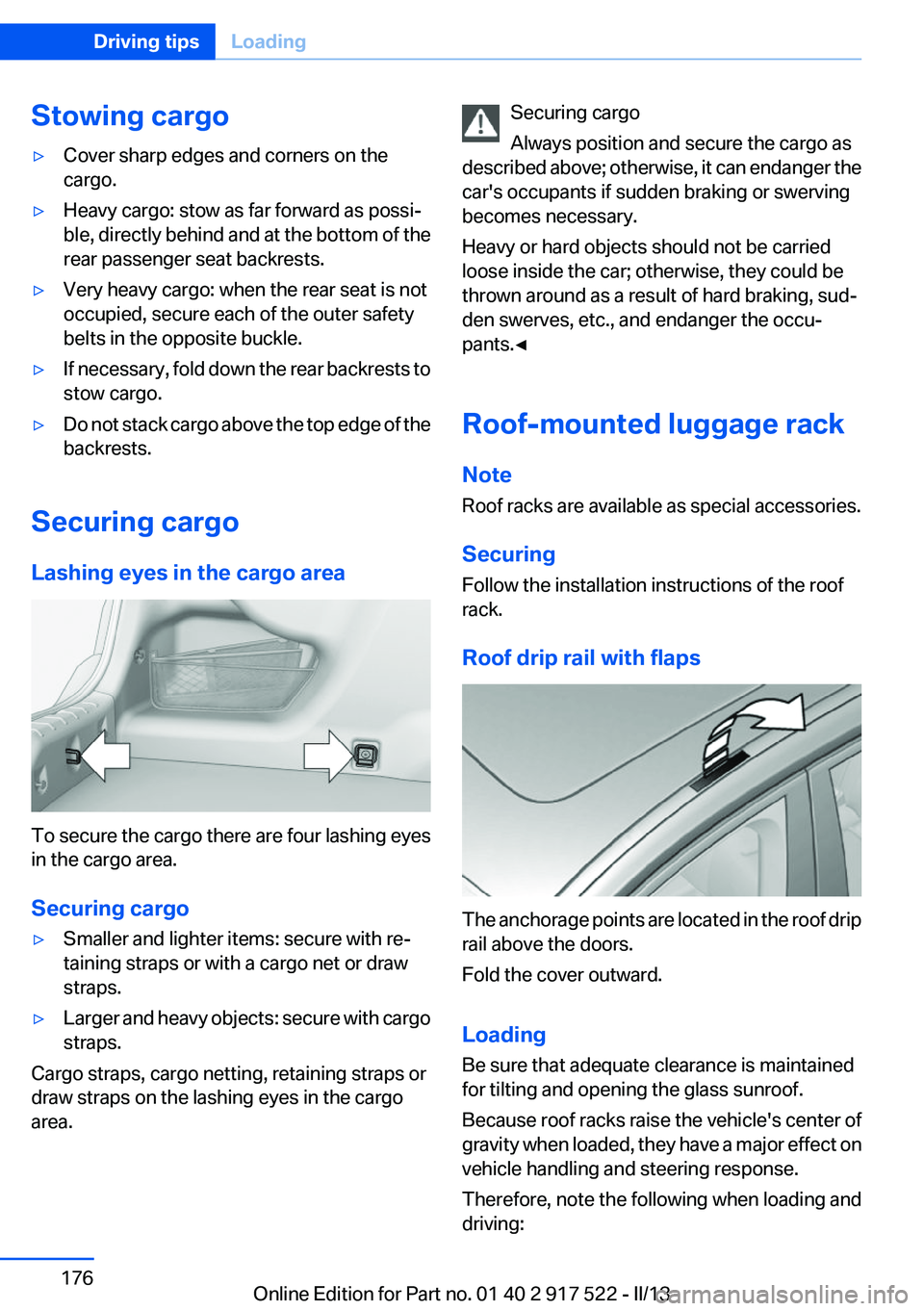
To secure the cargo there are four lashing eyes
in the cargo area.
Securing cargo
▷Smaller and lighter items: secure with re‐
taining straps or with a cargo net or draw
straps.▷Larger and heavy objects: secure with cargo
straps.
Cargo straps, cargo netting, retaining straps or
draw straps on the lashing eyes in the cargo
area.
Securing cargo
Always position and secure the cargo as
described above; otherwise, it can endanger the
car's occupants if sudden braking or swerving
becomes necessary.
Heavy or hard objects should not be carried
loose inside the car; otherwise, they could be
thrown around as a result of hard braking, sud‐
den swerves, etc., and endanger the occu‐
pants.◀
Roof-mounted luggage rack
Note
Roof racks are available as special accessories.
Securing
Follow the installation instructions of the roof
rack.
Roof drip rail with flaps
The anchorage points are located in the roof drip
rail above the doors.
Fold the cover outward.
Loading
Be sure that adequate clearance is maintained
for tilting and opening the glass sunroof.
Because roof racks raise the vehicle's center of
gravity when loaded, they have a major effect on
vehicle handling and steering response.
Therefore, note the following when loading and
driving:
Seite 176Driving tipsLoading176
Online Edition for Part no. 01 40 2 917 522 - II/13
Page 199 of 246
xxxx: manufacturer code for the tire brand
xxx: tire size and tire design
3510: tire age
Tires with DOT codes meet the guidelines of the
U.S. Department of Transportation.
Tire age
DOT … 3510: the tire was manufactured in the
35th week in 2010.
Recommendation
Regardless of wear, replace tires at least every
6 years.
Uniform Tire Quality Grading
Quality grades can be found where applicable
on the tire sidewall between tread shoulder and
maximum section width.
For example: Treadwear 200; Traction AA;
Temperature A
DOT Quality Grades
Treadwear
Traction AA A B C
Temperature A B C
All passenger car tires must conform to Federal
Safety Requirements in addition to these
grades.
Treadwear
The treadwear grade is a comparative rating
based on the wear rate of the tire when tested
under controlled conditions on a specified gov‐
ernment test course. For example, a tire graded
150 would wear one and one-half, 1 g, times as
well on the government course as a tire graded
100. The relative performance of tires depends
upon the actual conditions of their use, however,
and may depart significantly from the norm due
to variations in driving habits, service practices
and differences in road characteristics and cli‐
mate.Traction
The traction grades, from highest to lowest, are
AA, A, B, and C.
Those grades represent the tire's ability to stop
on wet pavement as measured under controlled
conditions on specified government test surfa‐
ces of asphalt and concrete. A tire marked C may
have poor traction performance.
The traction grade assigned to this tire is based
on straight-ahead braking traction tests, and
does not include acceleration, cornering, hydro‐
planing, or peak traction characteristics.
Temperature
The temperature grades are A, the highest, B,
and C, representing the tire's resistance to the
generation of heat and its ability to dissipate
heat when tested under controlled conditions
on a specified indoor laboratory test wheel. Sus‐
tained high temperature can cause the material
of the tire to degenerate and reduce tire life, and
excessive temperature can lead to sudden tire
failure. The grade C corresponds to a level of
performance which all passenger car tires must
meet under the Federal Motor Vehicle Safety
Standard No. 109. Grades Band A represent
higher levels of performance on the laboratory
test wheel than the minimum required by law.
Temperature grade for this tire
The temperature grade for this tire is es‐
tablished for a tire that is properly inflated and
not overloaded. Excessive speed, underinfla‐
tion, or excessive loading, either separately or in
combination, can cause heat buildup and pos‐
sible tire failure.
If necessary, have the vehicle towed.◀
RSC – Run-flat tires
Run-flat tires, refer to page 202, are labeled with
a circular symbol containing the letters RSC
marked on the sidewall.Seite 199Wheels and tiresMobility199
Online Edition for Part no. 01 40 2 917 522 - II/13
Page 200 of 246

M+S
Winter and all-season tires with better cold
weather performance than summer tires.
Tire tread
Summer tires
Do not drive with a tire tread depth of less than
0.12 in/3 mm.
There is an increased danger of hydroplaning if
the tread depth is less than 0.12 in/3 mm.
Winter tires
Do not drive with a tire tread depth of less than
0.16 in/4 mm.
Below a tread depth of 0.16 in/4 mm, tires are
less suitable for winter operation.
Minimum tread depth
Wear indicators are distributed around the tire's
circumference and have the legally required
minimum height of 0.063 in/1.6 mm.
They are marked on the side of the tire with TWI,
Tread Wear Indicator.
Tire damage
General information
Inspect your tires often for damage, foreign ob‐
jects lodged in the tread, and tread wear.
Notes
Driving over rough or damaged road surfaces, as
well as debris, curbs and other obstacles can
cause serious damage to wheels, tires and sus‐
pension parts. This is more likely to occur with
low-profile tires, which provide less cushioning
between the wheel and the road. Be careful to
avoid road hazards and reduce your speed, es‐
pecially if your vehicle is equipped with low-pro‐
file tires.
Indications of tire damage or other vehicle de‐
fects:▷Unusual vibrations during driving.▷Unusual handling such as a strong tendency
to pull to the left or right.
Damage can, e. g., be caused by driving over
curbs, road damage, or similar things.
In case of tire damage
If there are indications of tire damage, re‐
duce your speed immediately and have the
wheels and tires checked right away; otherwise,
there is the increased risk of an accident.
Drive carefully to the next service center or tire
shop.
If necessary, have the vehicle towed.
Otherwise, tire damage can be life-threatening
for vehicle occupants and other traffic partici‐
pants.◀
Repair of tire damage
For safety reasons, the manufacturer of
your vehicle recommends that you do not have
damaged tires repaired; they should be re‐
placed. Otherwise, damage can occur as a re‐
sult.◀
Seite 200MobilityWheels and tires200
Online Edition for Part no. 01 40 2 917 522 - II/13
Page 212 of 246
Replacing componentsVehicle equipment
All standard, country-specific and optional
equipment that is offered in the model series is
described in this chapter. Therefore, equipment
is also described that is not available in a vehicle,
e. g., because of the selected optional equip‐
ment or country variant. This also applies for
safety-related functions and systems.
Onboard vehicle tool kit
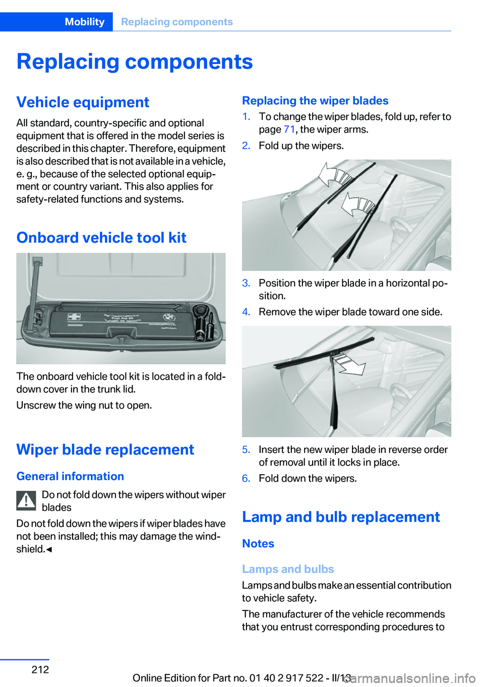
The onboard vehicle tool kit is located in a fold-
down cover in the trunk lid.
Unscrew the wing nut to open.
Wiper blade replacement
General information Do not fold down the wipers without wiper
blades
Do not fold down the wipers if wiper blades have
not been installed; this may damage the wind‐
shield.◀
Replacing the wiper blades1.To change the wiper blades, fold up, refer to
page 71, the wiper arms.2.Fold up the wipers.3.Position the wiper blade in a horizontal po‐
sition.4.Remove the wiper blade toward one side.5.Insert the new wiper blade in reverse order
of removal until it locks in place.6.Fold down the wipers.
Lamp and bulb replacement
Notes
Lamps and bulbs
Lamps and bulbs make an essential contribution
to vehicle safety.
The manufacturer of the vehicle recommends
that you entrust corresponding procedures to
Seite 212MobilityReplacing components212
Online Edition for Part no. 01 40 2 917 522 - II/13
Page 216 of 246
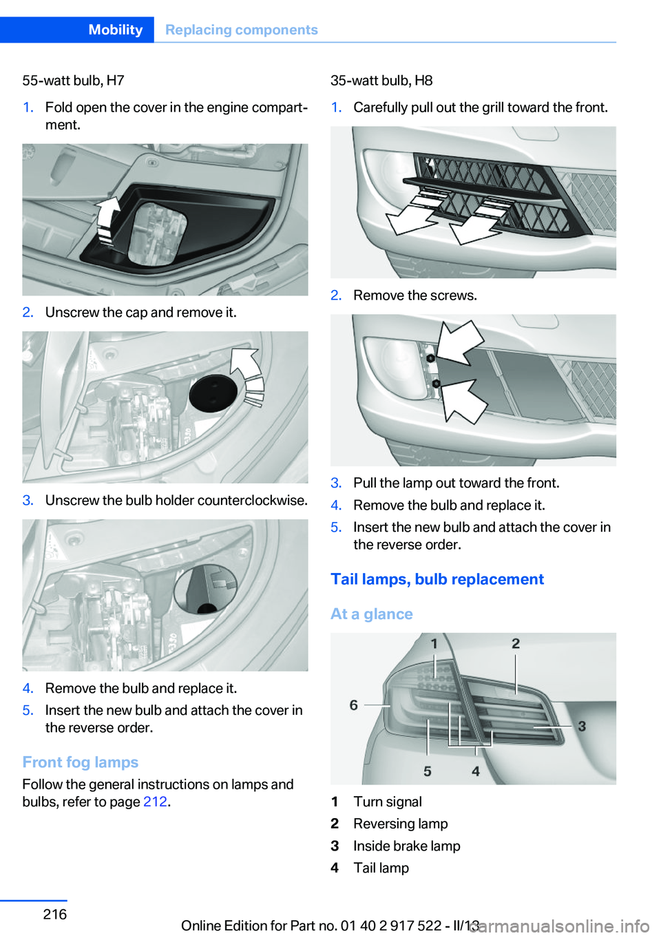
55-watt bulb, H71.Fold open the cover in the engine compart‐
ment.2.Unscrew the cap and remove it.3.Unscrew the bulb holder counterclockwise.4.Remove the bulb and replace it.5.Insert the new bulb and attach the cover in
the reverse order.
Front fog lamps
Follow the general instructions on lamps and
bulbs, refer to page 212.
35-watt bulb, H81.Carefully pull out the grill toward the front.2.Remove the screws.3.Pull the lamp out toward the front.4.Remove the bulb and replace it.5.Insert the new bulb and attach the cover in
the reverse order.
Tail lamps, bulb replacement
At a glance
1Turn signal2Reversing lamp3Inside brake lamp4Tail lampSeite 216MobilityReplacing components216
Online Edition for Part no. 01 40 2 917 522 - II/13
Page 223 of 246
3.Let both engines run for several minutes.4.Disconnect the jumper cables in the reverse
order.
Check the battery and recharge if necessary.
Tow-starting and towing
Automatic transmission: transporting
your vehicle
Note
Your vehicle is not permitted to be towed.
Therefore, contact a service center in the event
of a breakdown.
Do not have the vehicle towed
Have your vehicle transported on a loading
platform only; otherwise, damage may occur.◀
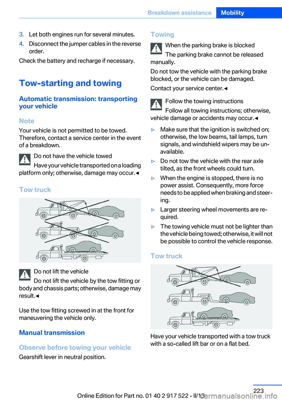
Tow truck
Do not lift the vehicle
Do not lift the vehicle by the tow fitting or
body and chassis parts; otherwise, damage may
result.◀
Use the tow fitting screwed in at the front for
maneuvering the vehicle only.
Manual transmission
Observe before towing your vehicle
Gearshift lever in neutral position.
Towing
When the parking brake is blocked
The parking brake cannot be released
manually.
Do not tow the vehicle with the parking brake
blocked, or the vehicle can be damaged.
Contact your service center.◀
Follow the towing instructions
Follow all towing instructions; otherwise,
vehicle damage or accidents may occur.◀▷Make sure that the ignition is switched on;
otherwise, the low beams, tail lamps, turn
signals, and windshield wipers may be un‐
available.▷Do not tow the vehicle with the rear axle
tilted, as the front wheels could turn.▷When the engine is stopped, there is no
power assist. Consequently, more force
needs to be applied when braking and steer‐
ing.▷Larger steering wheel movements are re‐
quired.▷The towing vehicle must not be lighter than
the vehicle being towed; otherwise, it will not
be possible to control the vehicle response.
Tow truck
Have your vehicle transported with a tow truck
with a so-called lift bar or on a flat bed.
Seite 223Breakdown assistanceMobility223
Online Edition for Part no. 01 40 2 917 522 - II/13
Page 224 of 246
Do not lift the vehicle
Do not lift the vehicle by the tow fitting or
body and chassis parts; otherwise, damage may
result.◀
Towing other vehicles
General information Light towing vehicle
The towing vehicle must not be lighter
than the vehicle being towed; otherwise, it will
not be possible to control the vehicle re‐
sponse.◀
Attaching the tow bar/tow rope correctly
Attach the tow bar or tow rope to the tow
fitting; connecting it to other vehicle parts may
cause damage.◀▷Switch on the hazard warning system, de‐
pending on local regulations.▷If the electrical system has failed, clearly
identify the vehicle being towed by placing
a sign or a warning triangle in the rear win‐
dow.
Tow bar
The tow fittings used should be on the same
side on both vehicles.
Should it prove impossible to avoid mounting
the tow bar at an offset angle, please observe
the following:
▷Maneuvering capability is limited during cor‐
nering.▷The tow bar will generate lateral forces if it
is secured with an offset.
Tow rope
When starting to tow the vehicle, make sure that
the tow rope is taut.
To avoid jerking and the associated stresses on
the vehicle components when towing, always
use nylon ropes or nylon straps.
Attaching the tow rope correctly
Only secure the tow rope on the tow fit‐
ting; otherwise, damage can occur when it is se‐
cured on other parts of the vehicle.◀
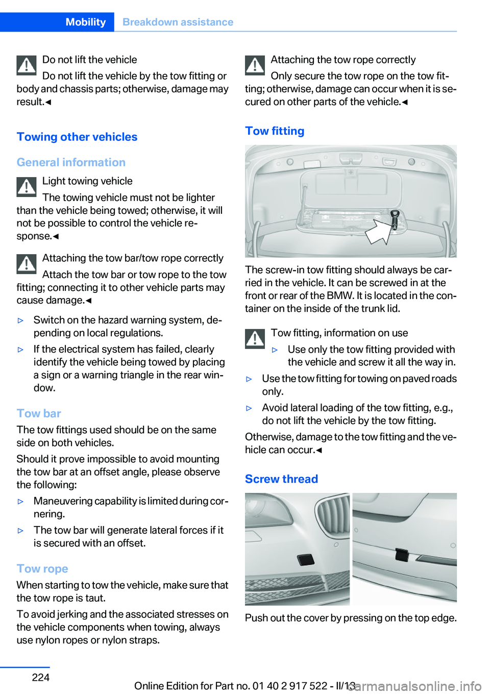
Tow fitting
The screw-in tow fitting should always be car‐
ried in the vehicle. It can be screwed in at the
front or rear of the BMW. It is located in the con‐
tainer on the inside of the trunk lid.
Tow fitting, information on use
▷Use only the tow fitting provided with
the vehicle and screw it all the way in.▷Use the tow fitting for towing on paved roads
only.▷Avoid lateral loading of the tow fitting, e.g.,
do not lift the vehicle by the tow fitting.
Otherwise, damage to the tow fitting and the ve‐
hicle can occur.◀
Screw thread
Push out the cover by pressing on the top edge.
Seite 224MobilityBreakdown assistance224
Online Edition for Part no. 01 40 2 917 522 - II/13
Page 225 of 246
Tow-starting
Automatic transmission
Do not tow-start the vehicle.
Due to the automatic transmission, the engine
cannot be started by tow-starting.
Have the cause of the starting difficulties rem‐
edied.
Manual transmission
If possible, do not tow-start the vehicle but start
the engine by jump-starting, refer to page 221.
If the vehicle is equipped with a catalytic con‐
verter, only tow-start while the engine is cold.1.Switch on the hazard warning system and
comply with local regulations.2.Ignition, refer to page 62, on.3.Engage third gear.4.Have the vehicle tow-started with the clutch
pedal pressed and slowly release the pedal.
After the engine starts, immediately press
on the clutch pedal again.5.Stop at a suitable location, remove the tow
bar or rope, and switch off the hazard warn‐
ing system.6.Have the vehicle checked.Seite 225Breakdown assistanceMobility225
Online Edition for Part no. 01 40 2 917 522 - II/13