2013 BMW 535I XDRIVE Control arm
[x] Cancel search: Control armPage 117 of 246
▷NBG009014A.
Compliance statement:
This device complies with part 15 of the FCC
Rules. Operation is subject to the following two
conditions:
▷This device may not cause harmful interfer‐
ence, and▷this device must accept any interference re‐
ceived, including interference that may
cause undesired operation.
Any unauthorized modifications or changes to
these devices could void the user's authority to
operate this equipment.
Brake force display
The concept
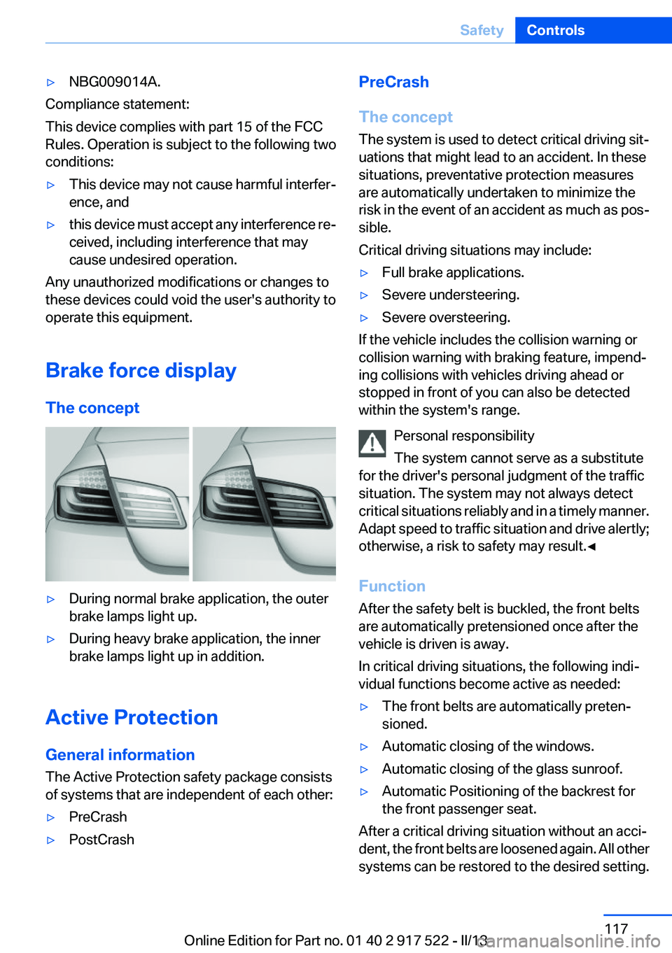
▷During normal brake application, the outer
brake lamps light up.▷During heavy brake application, the inner
brake lamps light up in addition.
Active Protection
General information
The Active Protection safety package consists
of systems that are independent of each other:
▷PreCrash▷PostCrashPreCrash
The concept
The system is used to detect critical driving sit‐
uations that might lead to an accident. In these
situations, preventative protection measures
are automatically undertaken to minimize the
risk in the event of an accident as much as pos‐
sible.
Critical driving situations may include:▷Full brake applications.▷Severe understeering.▷Severe oversteering.
If the vehicle includes the collision warning or
collision warning with braking feature, impend‐
ing collisions with vehicles driving ahead or
stopped in front of you can also be detected
within the system's range.
Personal responsibility
The system cannot serve as a substitute
for the driver's personal judgment of the traffic
situation. The system may not always detect
critical situations reliably and in a timely manner.
Adapt speed to traffic situation and drive alertly;
otherwise, a risk to safety may result.◀
Function
After the safety belt is buckled, the front belts
are automatically pretensioned once after the
vehicle is driven is away.
In critical driving situations, the following indi‐
vidual functions become active as needed:
▷The front belts are automatically preten‐
sioned.▷Automatic closing of the windows.▷Automatic closing of the glass sunroof.▷Automatic Positioning of the backrest for
the front passenger seat.
After a critical driving situation without an acci‐
dent, the front belts are loosened again. All other
systems can be restored to the desired setting.
Seite 117SafetyControls117
Online Edition for Part no. 01 40 2 917 522 - II/13
Page 132 of 246
Radar sensor
For US owners only
The transmitter and receiver units comply with
part 15 of the FCC/Federal Communication
Commission regulations. Operation is governed
by the following:
FCC ID:▷OAYARS3-A
Compliance statement:
This device complies with part 15 of the FCC
Rules. Operation is subject to the following two
conditions:
▷This device may not cause harmful interfer‐
ence, and▷this device must accept any interference re‐
ceived, including interference that may
cause undesired operation.
Any unauthorized modifications or changes to
these devices could void the user's authority to
operate this equipment.
Malfunction
The system cannot be activated if the radar sen‐
sor is not aligned correctly. This may be caused
by damage incurred during parking, for example.
A Check Control message is displayed if the
system fails.
Cruise control
The concept
The system is functional at speeds beginning at
approx. 20 mph/30 km/h.
It maintains the speed that was set using the
control elements on the steering wheel.
The system brakes on downhill gradients if en‐
gine braking action is insufficient.
Unfavorable conditions
Do not use the system if unfavorable con‐
ditions make it impossible to drive at a constant
speed, for instance:▷On curvy roads.▷In heavy traffic.▷On slippery roads, in fog, snow or rain, or on
a loose road surface.
Otherwise, you could lose control of the vehicle
and cause an accident.◀
Controls
At a glance
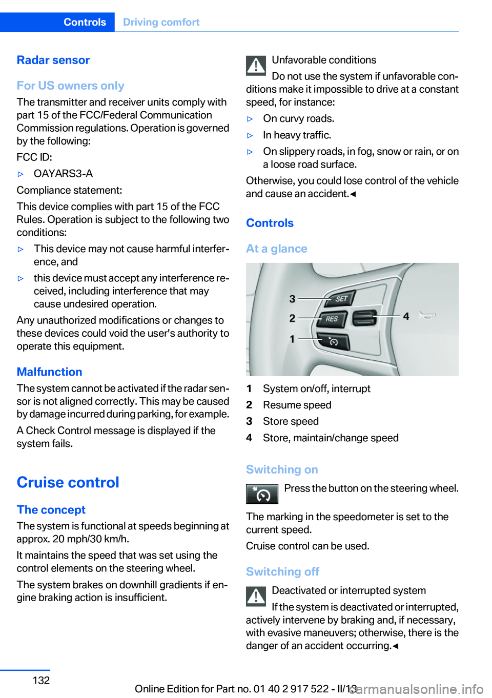
1System on/off, interrupt2Resume speed3Store speed4Store, maintain/change speed
Switching on Press the button on the steering wheel.
The marking in the speedometer is set to the
current speed.
Cruise control can be used.
Switching off Deactivated or interrupted system
If the system is deactivated or interrupted,
actively intervene by braking and, if necessary,
with evasive maneuvers; otherwise, there is the
danger of an accident occurring.◀
Seite 132ControlsDriving comfort132
Online Edition for Part no. 01 40 2 917 522 - II/13
Page 150 of 246
Air flows out of the vents for the upper body re‐
gion. The vents need to be open for this.
Air is cooled as quickly as possible:▷At an external temperature of approx.
32 ℉/0 ℃.▷When the engine is running.
The air flow can be adjusted when the program
is active.
Automatic recirculated-air control/
recirculated-air mode
You can respond to unpleasant odors or pollu‐
tants in the immediate environment by tempo‐
rarily suspending the supply of outside air. The
system then recirculates the air currently within
the vehicle.
Press the button repeatedly to select
an operating mode:
▷LEDs off: outside air flows in continuously.▷Left LED on, automatic recirculated-air con‐
trol: a sensor detects pollutants in the out‐
side air and controls the shutoff automati‐
cally.▷Right LED on, recirculated-air mode: the
supply of outside air into the vehicle is per‐
manently blocked.
If the windows are fogged over, switch off the
recirculated-air mode and press the AUTO but‐
ton on the driver's side to utilize the condensa‐
tion sensor. Make sure that air can flow onto the
windshield.
Continuous recirculated-air mode
The recirculated-air mode should not be
used for an extended period of time, as the air
quality inside the vehicle deteriorates steadily. ◀
Cooling function
The passenger compartment can only be
cooled with the engine running.
Press the button.
The air is cooled and dehumidified and, depend‐
ing on the temperature setting, warmed again.
Depending on the weather, the windshield may
fog up briefly when the engine is started.
The cooling function is switched on automati‐
cally with the AUTO program.
When using the automatic climate control, con‐
densation water, refer to page 174, develops
that exits underneath the vehicle.
Rear window defroster Press the button.
The rear window defroster switches off
automatically after a certain period of time.
ALL program The current settings on the driver's side
for temperature, air flow, air distribu‐
tion, and AUTO program are transferred to the
front passenger side and to the left and right
rear.
The program is switched off if the settings on
the front passenger side or in the rear are
changed.
Residual heat
The heat stored in the engine is used to heat the
interior.
Functional requirement▷Up to 20 minutes after the engine has been
switched off.▷Warm engine.▷The battery is sufficiently charged.▷External temperature below 77 ℉/25 ℃.
Switching on
1.Switch off the ignition.2. Press the right side of the button on
the driver's side.
Seite 150ControlsClimate control150
Online Edition for Part no. 01 40 2 917 522 - II/13
Page 151 of 246
is shown on the display of the automatic cli‐
mate control.
The interior temperature, air volume and air dis‐
tribution can be adjusted with the ignition
switched on.
Switching off
At the lowest fan speed, press the left side of the
button on the driver's side.
on the display of the automatic climate control
goes out.
Switching the system on/off
Switching off
▷Complete system: Press and hold the left button on
the driver's side until the control
clicks off.▷On the front passenger side:
Press and hold the left button on
the front passenger side.
Switching on
Press any button except:
▷ALL program.▷Rear window defroster.▷Left side of Air volume button.▷Seat heating.▷Seat ventilation.
Microfilter/activated-charcoal filter
The microfilter removes dust and pollen from
the incoming air.
The activated-charcoal filter removes gaseous
pollutants from the outside air that enters the
vehicle.
This combined filter should be replaced during
scheduled maintenance, refer to page 210, of
your vehicle.
Ventilation
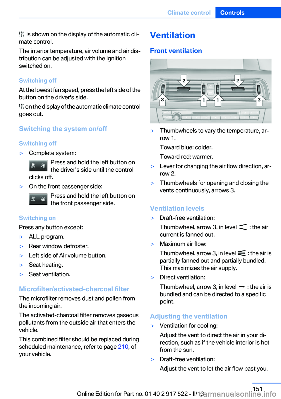
Front ventilation▷Thumbwheels to vary the temperature, ar‐
row 1.
Toward blue: colder.
Toward red: warmer.▷Lever for changing the air flow direction, ar‐
row 2.▷Thumbwheels for opening and closing the
vents continuously, arrows 3.
Ventilation levels
▷Draft-free ventilation:
Thumbwheel, arrow 3, in level
: the air
current is fanned out.
▷Maximum air flow:
Thumbwheel, arrow 3, in level
: the air is
partially fanned out and partially bundled.
This maximizes the air supply.
▷Direct ventilation:
Thumbwheel, arrow 3, in level
: the air is
bundled and can be directed to a specific
point.
Adjusting the ventilation
▷Ventilation for cooling:
Adjust the vent to direct the air in your di‐
rection, such as if the vehicle interior is hot
from the sun.▷Draft-free ventilation:
Adjust the vent to let the air flow past you.Seite 151Climate controlControls151
Online Edition for Part no. 01 40 2 917 522 - II/13
Page 152 of 246
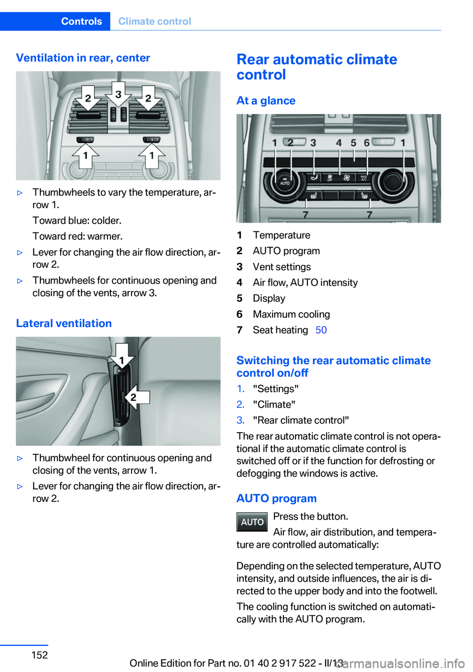
Ventilation in rear, center▷Thumbwheels to vary the temperature, ar‐
row 1.
Toward blue: colder.
Toward red: warmer.▷Lever for changing the air flow direction, ar‐
row 2.▷Thumbwheels for continuous opening and
closing of the vents, arrow 3.
Lateral ventilation
▷Thumbwheel for continuous opening and
closing of the vents, arrow 1.▷Lever for changing the air flow direction, ar‐
row 2.Rear automatic climate
control
At a glance1Temperature2AUTO program3Vent settings4Air flow, AUTO intensity5Display6Maximum cooling7Seat heating 50
Switching the rear automatic climate
control on/off
1."Settings"2."Climate"3."Rear climate control"
The rear automatic climate control is not opera‐
tional if the automatic climate control is
switched off or if the function for defrosting or
defogging the windows is active.
AUTO program Press the button.
Air flow, air distribution, and tempera‐
ture are controlled automatically:
Depending on the selected temperature, AUTO
intensity, and outside influences, the air is di‐
rected to the upper body and into the footwell.
The cooling function is switched on automati‐
cally with the AUTO program.
Seite 152ControlsClimate control152
Online Edition for Part no. 01 40 2 917 522 - II/13
Page 159 of 246
Replace the cover after use
Reinsert the lighter or socket cover after
use, otherwise objects may get into the lighter
socket or fixture and cause a short circuit.◀
Connecting electrical devices
Hints Do not plug chargers into the socket
Do not connect battery chargers to the
factory-installed sockets in the vehicle as this
may damage the battery.◀
Replace the cover after use
Reinsert the lighter or socket cover after
use, otherwise objects may get into the lighter
socket or fixture and cause a short circuit.◀
Sockets
The lighter socket can be used as a socket for
electrical equipment while the engine is running
or when the ignition is switched on. The total
load of all sockets must not exceed 140 watts at
12 volts.
Do not damage the socket by using unsuitable
connectors.
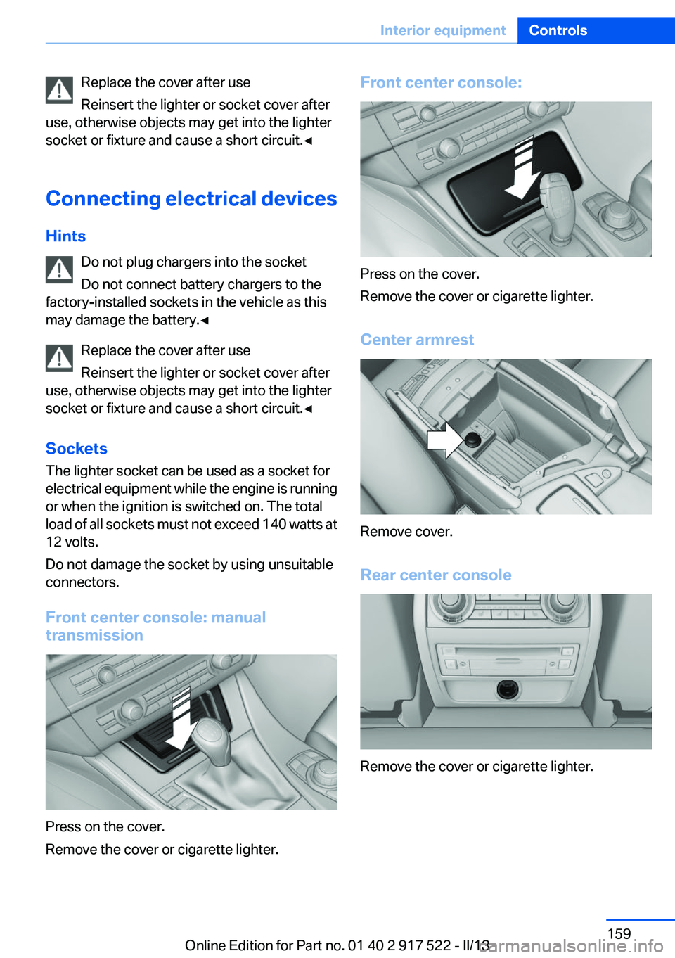
Front center console: manual
transmission
Press on the cover.
Remove the cover or cigarette lighter.
Front center console:
Press on the cover.
Remove the cover or cigarette lighter.
Center armrest
Remove cover.
Rear center console
Remove the cover or cigarette lighter.
Seite 159Interior equipmentControls159
Online Edition for Part no. 01 40 2 917 522 - II/13
Page 160 of 246
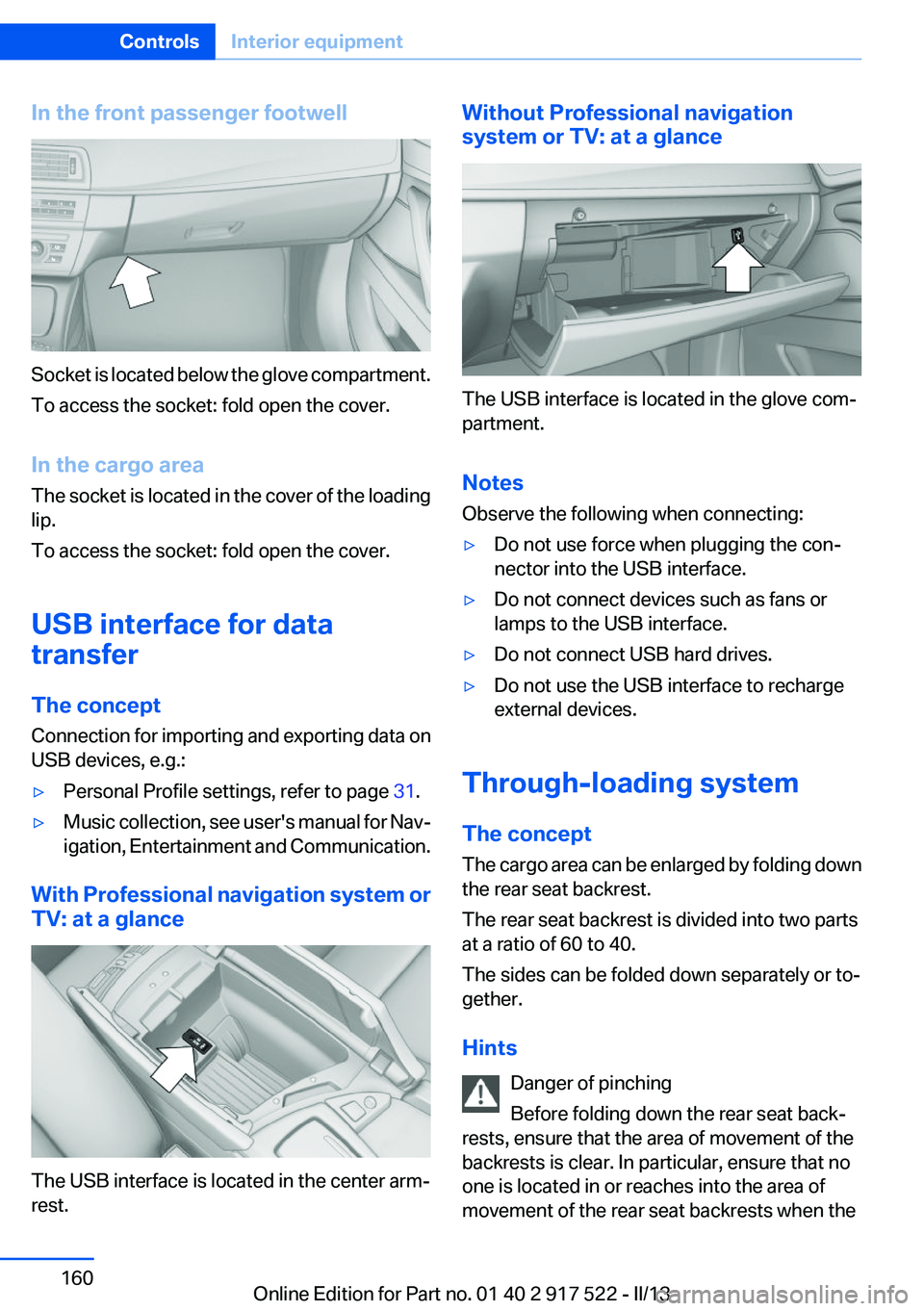
In the front passenger footwell
Socket is located below the glove compartment.
To access the socket: fold open the cover.
In the cargo area
The socket is located in the cover of the loading
lip.
To access the socket: fold open the cover.
USB interface for data
transfer
The concept
Connection for importing and exporting data on
USB devices, e.g.:
▷Personal Profile settings, refer to page 31.▷Music collection, see user's manual for Nav‐
igation, Entertainment and Communication.
With Professional navigation system or
TV: at a glance
The USB interface is located in the center arm‐
rest.
Without Professional navigation
system or TV: at a glance
The USB interface is located in the glove com‐
partment.
Notes
Observe the following when connecting:
▷Do not use force when plugging the con‐
nector into the USB interface.▷Do not connect devices such as fans or
lamps to the USB interface.▷Do not connect USB hard drives.▷Do not use the USB interface to recharge
external devices.
Through-loading system
The concept
The cargo area can be enlarged by folding down
the rear seat backrest.
The rear seat backrest is divided into two parts
at a ratio of 60 to 40.
The sides can be folded down separately or to‐
gether.
Hints Danger of pinching
Before folding down the rear seat back‐
rests, ensure that the area of movement of the
backrests is clear. In particular, ensure that no
one is located in or reaches into the area of
movement of the rear seat backrests when the
Seite 160ControlsInterior equipment160
Online Edition for Part no. 01 40 2 917 522 - II/13
Page 162 of 246
Ski bag
Capacity
The ski bag can be used to transport up to four
pairs of skis with a length of up to 6 ft/2.10 m or,
depending on the binding, up to two snow‐
boards with a length of up to 5 ft/1.60 m.
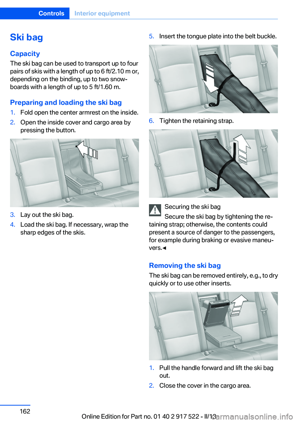
Preparing and loading the ski bag1.Fold open the center armrest on the inside.2.Open the inside cover and cargo area by
pressing the button.3.Lay out the ski bag.4.Load the ski bag. If necessary, wrap the
sharp edges of the skis.5.Insert the tongue plate into the belt buckle.6.Tighten the retaining strap.
Securing the ski bag
Secure the ski bag by tightening the re‐
taining strap; otherwise, the contents could
present a source of danger to the passengers,
for example during braking or evasive maneu‐
vers.◀
Removing the ski bag
The ski bag can be removed entirely, e.g., to dry
quickly or to use other inserts.
1.Pull the handle forward and lift the ski bag
out.2.Close the cover in the cargo area.Seite 162ControlsInterior equipment162
Online Edition for Part no. 01 40 2 917 522 - II/13