2013 BMW 535I XDRIVE navigation system
[x] Cancel search: navigation systemPage 89 of 246
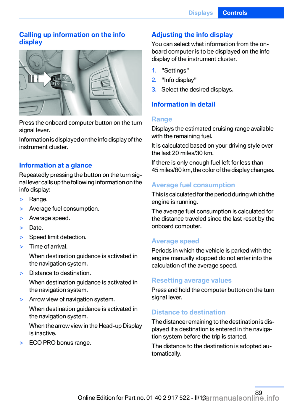
Calling up information on the info
display
Press the onboard computer button on the turn
signal lever.
Information is displayed on the info display of the
instrument cluster.
Information at a glance
Repeatedly pressing the button on the turn sig‐
nal lever calls up the following information on the
info display:
▷Range.▷Average fuel consumption.▷Average speed.▷Date.▷Speed limit detection.▷Time of arrival.
When destination guidance is activated in
the navigation system.▷Distance to destination.
When destination guidance is activated in
the navigation system.▷Arrow view of navigation system.
When destination guidance is activated in
the navigation system.
When the arrow view in the Head-up Display
is inactive.▷ECO PRO bonus range.Adjusting the info display
You can select what information from the on‐
board computer is to be displayed on the info
display of the instrument cluster.1."Settings"2."Info display"3.Select the desired displays.
Information in detail
Range
Displays the estimated cruising range available
with the remaining fuel.
It is calculated based on your driving style over
the last 20 miles/30 km.
If there is only enough fuel left for less than
45 miles/80 km, the color of the display changes.
Average fuel consumption
This is calculated for the period during which the
engine is running.
The average fuel consumption is calculated for
the distance traveled since the last reset by the
onboard computer.
Average speed
Periods in which the vehicle is parked with the
engine manually stopped do not enter into the
calculation of the average speed.
Resetting average values
Press and hold the computer button on the turn
signal lever.
Distance to destination
The distance remaining to the destination is dis‐
played if a destination is entered in the naviga‐
tion system before the trip is started.
The distance to the destination is adopted au‐
tomatically.
Seite 89DisplaysControls89
Online Edition for Part no. 01 40 2 917 522 - II/13
Page 90 of 246
Time of arrivalThe estimated time of arrival is
displayed if a destination is en‐
tered in the navigation system
before the trip is started.
The time must be correctly set.
Speed limit detection
Description of the speed limit detection, refer to
page 86, function.
Speed limit
Display of a speed limit which, when reached,
should cause a warning to be issued.
The warning is repeated if the vehicle speed
drops below the set speed limit once by at least
3 mph/5 km/h.
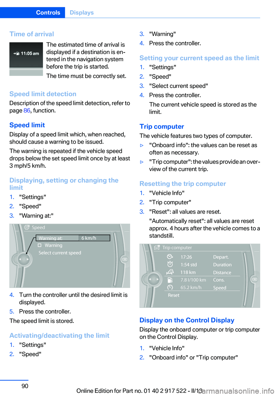
Displaying, setting or changing the
limit1."Settings"2."Speed"3."Warning at:"4.Turn the controller until the desired limit is
displayed.5.Press the controller.
The speed limit is stored.
Activating/deactivating the limit
1."Settings"2."Speed"3."Warning"4.Press the controller.
Setting your current speed as the limit
1."Settings"2."Speed"3."Select current speed"4.Press the controller.
The current vehicle speed is stored as the
limit.
Trip computer
The vehicle features two types of computer.
▷"Onboard info": the values can be reset as
often as necessary.▷" Trip computer": the values provide an over‐
view of the current trip.
Resetting the trip computer
1."Vehicle Info"2."Trip computer"3."Reset": all values are reset.
"Automatically reset": all values are reset
approx. 4 hours after the vehicle comes to a
standstill.
Display on the Control Display
Display the onboard computer or trip computer
on the Control Display.
1."Vehicle Info"2."Onboard info" or "Trip computer"Seite 90ControlsDisplays90
Online Edition for Part no. 01 40 2 917 522 - II/13
Page 100 of 246
Protective action
Airbags are not triggered in every impact situa‐
tion, e.g., in less severe accidents or rear-end
collisions.
Information on how to ensure the optimal
protective effect of the airbags▷Keep at a distance from the airbags.▷Always grasp the steering wheel on the
steering wheel rim, holding your hands at
the 3 o'clock and 9 o'clock positions, to keep
the danger of injury to your hands or arms as
low as possible if the airbag is triggered.▷There should be no people, animals, or ob‐
jects between an airbag and a person.▷Do not use the cover of the front airbag on
the front passenger side as a storage area.▷Keep the dashboard and window on the
front passenger side clear, i.e., do not cover
with adhesive labels or coverings, and do not
attach holders such as for navigation instru‐
ments and mobile phones.▷Make sure that the front passenger is sitting
correctly, i.e., keeps his or her feet and legs
in the footwell; otherwise, leg injuries can
occur if the front airbag is triggered.▷Do not place slip covers, seat cushions or
other objects on the front passenger seat
that are not approved specifically for seats
with integrated side airbags.▷Do not hang pieces of clothing, such as jack‐
ets, over the backrests.▷Make sure that occupants keep their heads
away from the side airbag and do not rest
against the head airbag; otherwise, injuries
can occur if the airbags are triggered.▷Do not remove the airbag restraint system.▷Do not remove the steering wheel.▷Do not apply adhesive materials to the air‐
bag cover panels, cover them or modify
them in any way.▷Never modify either the individual compo‐
nents or the wiring in the airbag system. This
also applies to steering wheel covers, the
dashboard, the seats, the roof pillars and the
sides of the headliner.◀
Even when all instructions are followed closely,
injury from contact with the airbags cannot be
ruled out in certain situations.
The ignition and inflation noise may lead to
short-term and, in most cases, temporary hear‐
ing impairment in sensitive individuals.
In the case of a malfunction, deactivation
and after triggering of the airbags
Do not touch the individual components imme‐
diately after the system has been triggered; oth‐
erwise, there is the danger of burns.
Only have the airbags checked, repaired or dis‐
mantled and the airbag generator scrapped by
your service center or a workshop that has the
necessary authorization for handling explosives.
Non-professional attempts to service the sys‐
tem could lead to failure in an emergency or un‐
desired triggering of the airbag, either of which
could result in injury.◀
Warnings and information on the airbags are
also found on the sun visors.
Functional readiness of the airbag
system
When the ignition is switch on, the warn‐
ing lamp in the instrument cluster lights
up briefly and thereby indicates the op‐
erational readiness of the entire airbag system
and the belt tensioner.
Airbag system malfunctioning
▷Warning lamp does not come on when the
ignition is turned on.▷The warning lamp lights up continuously.Seite 100ControlsSafety100
Online Edition for Part no. 01 40 2 917 522 - II/13
Page 135 of 246
At a glance
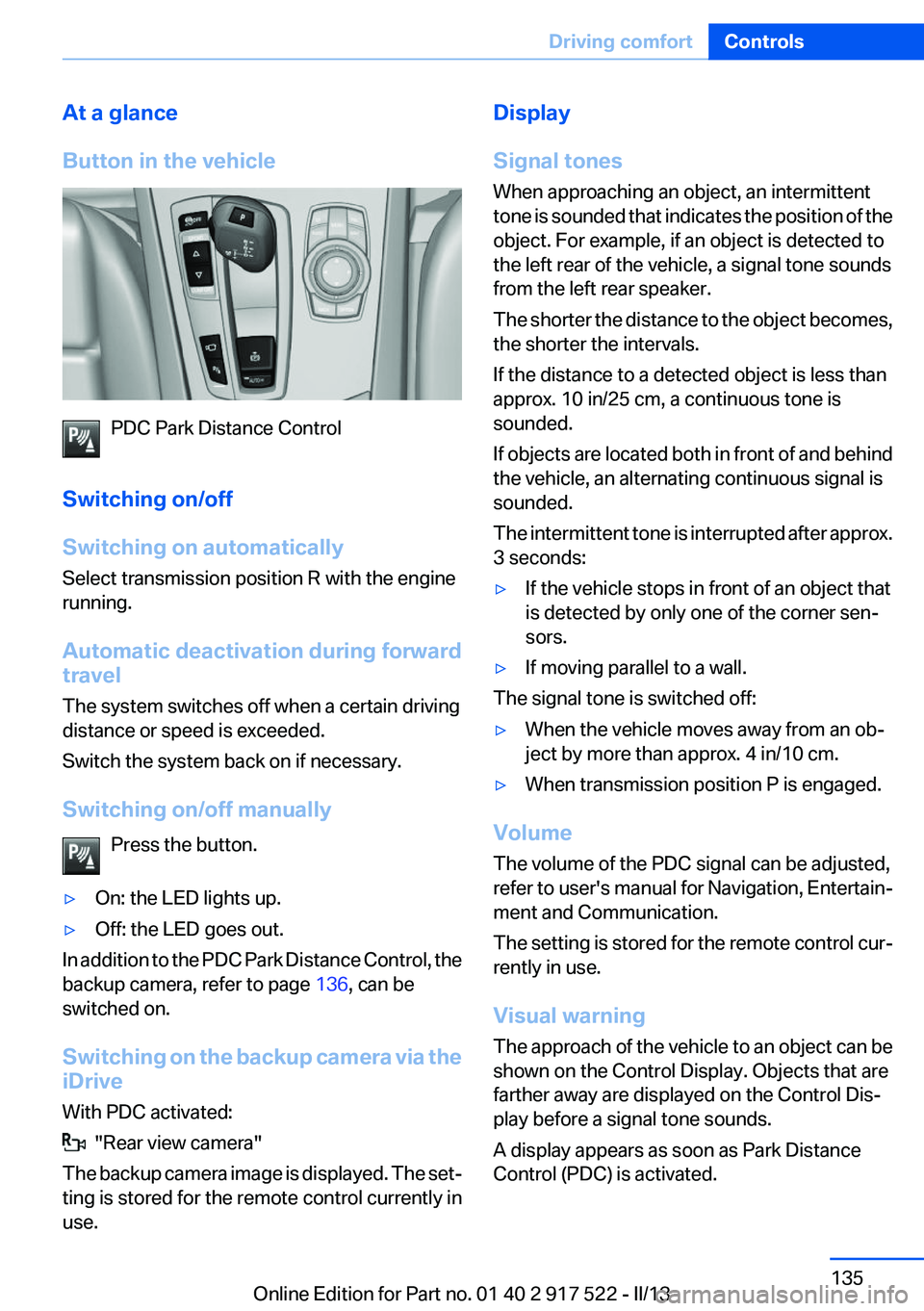
Button in the vehicle
PDC Park Distance Control
Switching on/off
Switching on automatically
Select transmission position R with the engine
running.
Automatic deactivation during forward
travel
The system switches off when a certain driving
distance or speed is exceeded.
Switch the system back on if necessary.
Switching on/off manually Press the button.
▷On: the LED lights up.▷Off: the LED goes out.
In addition to the PDC Park Distance Control, the
backup camera, refer to page 136, can be
switched on.
Switching on the backup camera via the
iDrive
With PDC activated:
"Rear view camera"
The backup camera image is displayed. The set‐
ting is stored for the remote control currently in
use.
Display
Signal tones
When approaching an object, an intermittent
tone is sounded that indicates the position of the
object. For example, if an object is detected to
the left rear of the vehicle, a signal tone sounds
from the left rear speaker.
The shorter the distance to the object becomes,
the shorter the intervals.
If the distance to a detected object is less than
approx. 10 in/25 cm, a continuous tone is
sounded.
If objects are located both in front of and behind
the vehicle, an alternating continuous signal is
sounded.
The intermittent tone is interrupted after approx.
3 seconds:▷If the vehicle stops in front of an object that
is detected by only one of the corner sen‐
sors.▷If moving parallel to a wall.
The signal tone is switched off:
▷When the vehicle moves away from an ob‐
ject by more than approx. 4 in/10 cm.▷When transmission position P is engaged.
Volume
The volume of the PDC signal can be adjusted,
refer to user's manual for Navigation, Entertain‐
ment and Communication.
The setting is stored for the remote control cur‐
rently in use.
Visual warning
The approach of the vehicle to an object can be
shown on the Control Display. Objects that are
farther away are displayed on the Control Dis‐
play before a signal tone sounds.
A display appears as soon as Park Distance
Control (PDC) is activated.
Seite 135Driving comfortControls135
Online Edition for Part no. 01 40 2 917 522 - II/13
Page 144 of 246
Switching on with reverse gear
Shift into reverse.
The current status of the parking space search
is indicated on the Control Display.
Activate:
"Parking Assistant" Select the
symbol in the Control Display.
Switching off
The system can be deactivated as follows:
▷Press the button.▷Switch off the ignition.
Display on the Control Display
Activating/deactivating the system
SymbolMeaning Gray: the system is not available.
White: the system is available but not
activated. The system is activated.
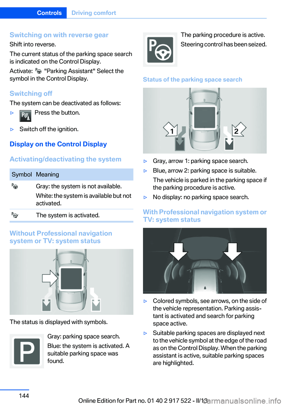
Without Professional navigation
system or TV: system status
The status is displayed with symbols.
Gray: parking space search.
Blue: the system is activated. A
suitable parking space was
found.
The parking procedure is active.
Steering control has been seized.
Status of the parking space search▷Gray, arrow 1: parking space search.▷Blue, arrow 2: parking space is suitable.
The vehicle is parked in the parking space if
the parking procedure is active.▷No display: no parking space search.
With Professional navigation system or
TV: system status
▷Colored symbols, see arrows, on the side of
the vehicle representation. Parking assis‐
tant is activated and search for parking
space active.▷Suitable parking spaces are displayed next
to the vehicle symbol at the edge of the road
as on the Control Display. When the parking
assistant is active, suitable parking spaces
are highlighted.Seite 144ControlsDriving comfort144
Online Edition for Part no. 01 40 2 917 522 - II/13
Page 146 of 246
Limits of ultrasonic measurement
The detection of objects can reach the physical
limits of ultrasonic measurement, e.g., in the fol‐
lowing circumstances:▷With tow bars and trailer hitches.▷With thin or wedge-shaped objects.▷With elevated, protruding objects such as
ledges or cargo.▷With objects with corners and sharp edges.▷With objects with a fine surface structure,
such as fences.
Low objects already displayed, e.g., curbs, can
move into the blind area of the sensors before or
after a continuous tone sounds.
High, protruding objects such as ledges may not
be detected.
The parking assistant may identify parking
spaces that are not suitable for parking.
Malfunction
A Check Control message is displayed.
The parking assistant failed. Have the system
checked.
Head-up Display
The concept
This system projects important information into
the driver's field of vision, e.g., the speed.
In this way, the driver can get information with‐
out averting his or her eyes from the road.
Display visibility
The visibility of the displays in the Head-up Dis‐
play is influenced by:▷Certain sitting positions.▷Objects on the cover of the Head-up Dis‐
play.▷Sunglasses with certain polarization filters.▷Wet roads.▷Unfavorable light conditions.
If the image is distorted, check the basic set‐
tings.
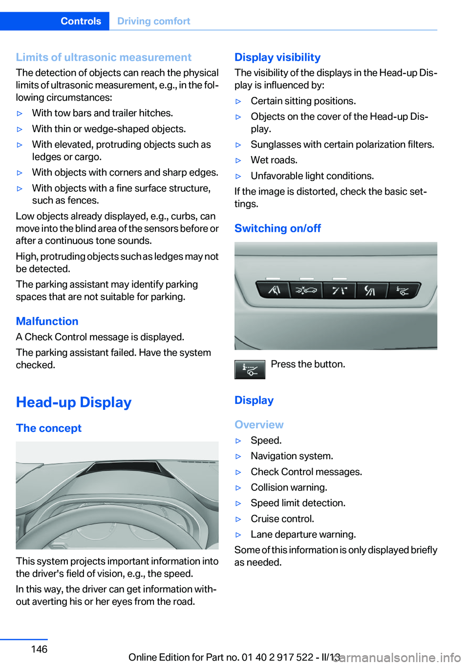
Switching on/off
Press the button.
Display
Overview
▷Speed.▷Navigation system.▷Check Control messages.▷Collision warning.▷Speed limit detection.▷Cruise control.▷Lane departure warning.
Some of this information is only displayed briefly
as needed.
Seite 146ControlsDriving comfort146
Online Edition for Part no. 01 40 2 917 522 - II/13
Page 160 of 246
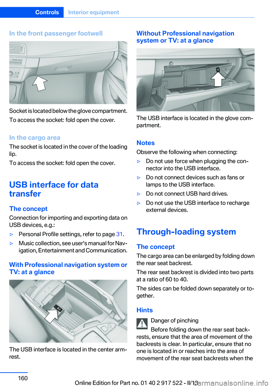
In the front passenger footwell
Socket is located below the glove compartment.
To access the socket: fold open the cover.
In the cargo area
The socket is located in the cover of the loading
lip.
To access the socket: fold open the cover.
USB interface for data
transfer
The concept
Connection for importing and exporting data on
USB devices, e.g.:
▷Personal Profile settings, refer to page 31.▷Music collection, see user's manual for Nav‐
igation, Entertainment and Communication.
With Professional navigation system or
TV: at a glance
The USB interface is located in the center arm‐
rest.
Without Professional navigation
system or TV: at a glance
The USB interface is located in the glove com‐
partment.
Notes
Observe the following when connecting:
▷Do not use force when plugging the con‐
nector into the USB interface.▷Do not connect devices such as fans or
lamps to the USB interface.▷Do not connect USB hard drives.▷Do not use the USB interface to recharge
external devices.
Through-loading system
The concept
The cargo area can be enlarged by folding down
the rear seat backrest.
The rear seat backrest is divided into two parts
at a ratio of 60 to 40.
The sides can be folded down separately or to‐
gether.
Hints Danger of pinching
Before folding down the rear seat back‐
rests, ensure that the area of movement of the
backrests is clear. In particular, ensure that no
one is located in or reaches into the area of
movement of the rear seat backrests when the
Seite 160ControlsInterior equipment160
Online Edition for Part no. 01 40 2 917 522 - II/13
Page 219 of 246
Starting aid terminals
In the vehicle, only charge the battery via the
starting aid terminals, refer to page 222, in the
engine compartment with the engine off.
Power failure
After a temporary power loss, some equipment
needs to be reinitialized.
Individual settings need to be reprogrammed:▷Seat, mirror, and steering wheel memory:
store the positions again.▷Time: update.▷Date: update.▷Radio station: save again.▷Navigation system: wait for the operability of
the navigation.
Disposing of old batteries
Have old batteries disposed of by your
service center or bring them to a recy‐
cling center.
Maintain the battery in an upright position for
transport and storage. Secure the battery so
that it does not tip over during transport.
Fuses
Notes Replacing fuses
Never attempt to repair a blown fuse and
do not replace a defective fuse with a substitute
of another color or amperage rating; this could
lead to a circuit overload, ultimately resulting in
a fire in the vehicle.◀
Plastic tweezers and information on the fuse
types and locations are stored in the fuse box in
the cargo area.
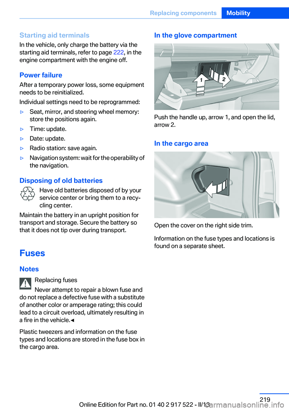
In the glove compartment
Push the handle up, arrow 1, and open the lid,
arrow 2.
In the cargo area
Open the cover on the right side trim.
Information on the fuse types and locations is
found on a separate sheet.
Seite 219Replacing componentsMobility219
Online Edition for Part no. 01 40 2 917 522 - II/13