Page 111 of 246

Functional limitations
The system may not be fully functional in the
following situations:▷In heavy fog, rain, sprayed water or snowfall.▷In tight curves.▷If the camera view field or the front wind‐
shield are dirty or covered.▷When driving toward bright lights.▷In the case of vehicles with insufficiently visi‐
ble tail lamps.▷In the case of partially covered vehicles.▷Up to 10 seconds after the start of the en‐
gine, via the Start/Stop knob.▷During the calibration process of the camera
immediately after vehicle shipment.
Prewarning sensitivity
Depending on the set prewarning time, this may
result in increased false warnings.
Camera
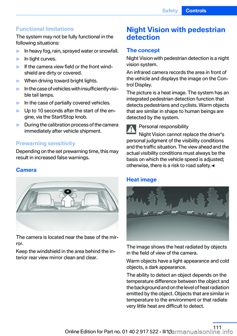
The camera is located near the base of the mir‐
ror.
Keep the windshield in the area behind the in‐
terior rear view mirror clean and clear.
Night Vision with pedestrian
detection
The concept
Night Vision with pedestrian detection is a night
vision system.
An infrared camera records the area in front of
the vehicle and displays the image on the Con‐
trol Display.
The picture is a heat image. The system has an
integrated pedestrian detection function that
detects pedestrians and cyclists. Warm objects
that are similar in shape to human beings are
detected by the system.
Personal responsibility
Night Vision cannot replace the driver's
personal judgment of the visibility conditions
and the traffic situation. The view ahead and the
actual visibility conditions must always be the
basis on which the vehicle speed is adjusted;
otherwise, there is a risk to road safety.◀
Heat image
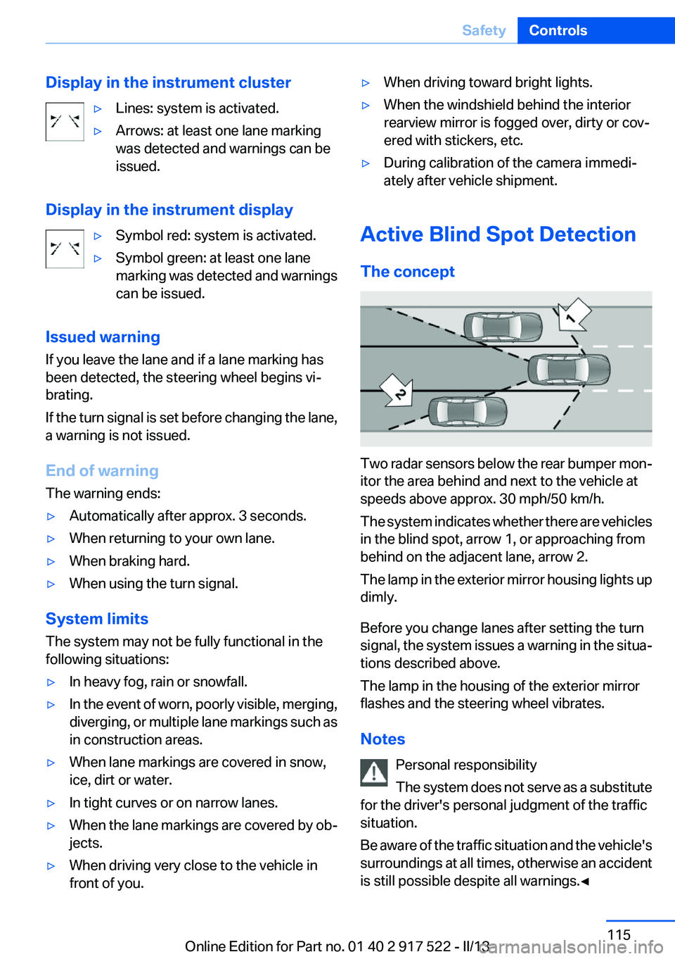
The image shows the heat radiated by objects
in the field of view of the camera.
Warm objects have a light appearance and cold
objects, a dark appearance.
The ability to detect an object depends on the
temperature difference between the object and
the background and on the level of heat radiation
emitted by the object. Objects that are similar in
temperature to the environment or that radiate
very little heat are difficult to detect.
Seite 111SafetyControls111
Online Edition for Part no. 01 40 2 917 522 - II/13
Page 115 of 246

Display in the instrument cluster▷Lines: system is activated.▷Arrows: at least one lane marking
was detected and warnings can be
issued.
Display in the instrument display
▷Symbol red: system is activated.▷Symbol green: at least one lane
marking was detected and warnings
can be issued.
Issued warning
If you leave the lane and if a lane marking has
been detected, the steering wheel begins vi‐
brating.
If the turn signal is set before changing the lane,
a warning is not issued.
End of warning
The warning ends:
▷Automatically after approx. 3 seconds.▷When returning to your own lane.▷When braking hard.▷When using the turn signal.
System limits
The system may not be fully functional in the
following situations:
▷In heavy fog, rain or snowfall.▷In the event of worn, poorly visible, merging,
diverging, or multiple lane markings such as
in construction areas.▷When lane markings are covered in snow,
ice, dirt or water.▷In tight curves or on narrow lanes.▷When the lane markings are covered by ob‐
jects.▷When driving very close to the vehicle in
front of you.▷When driving toward bright lights.▷When the windshield behind the interior
rearview mirror is fogged over, dirty or cov‐
ered with stickers, etc.▷During calibration of the camera immedi‐
ately after vehicle shipment.
Active Blind Spot Detection
The concept
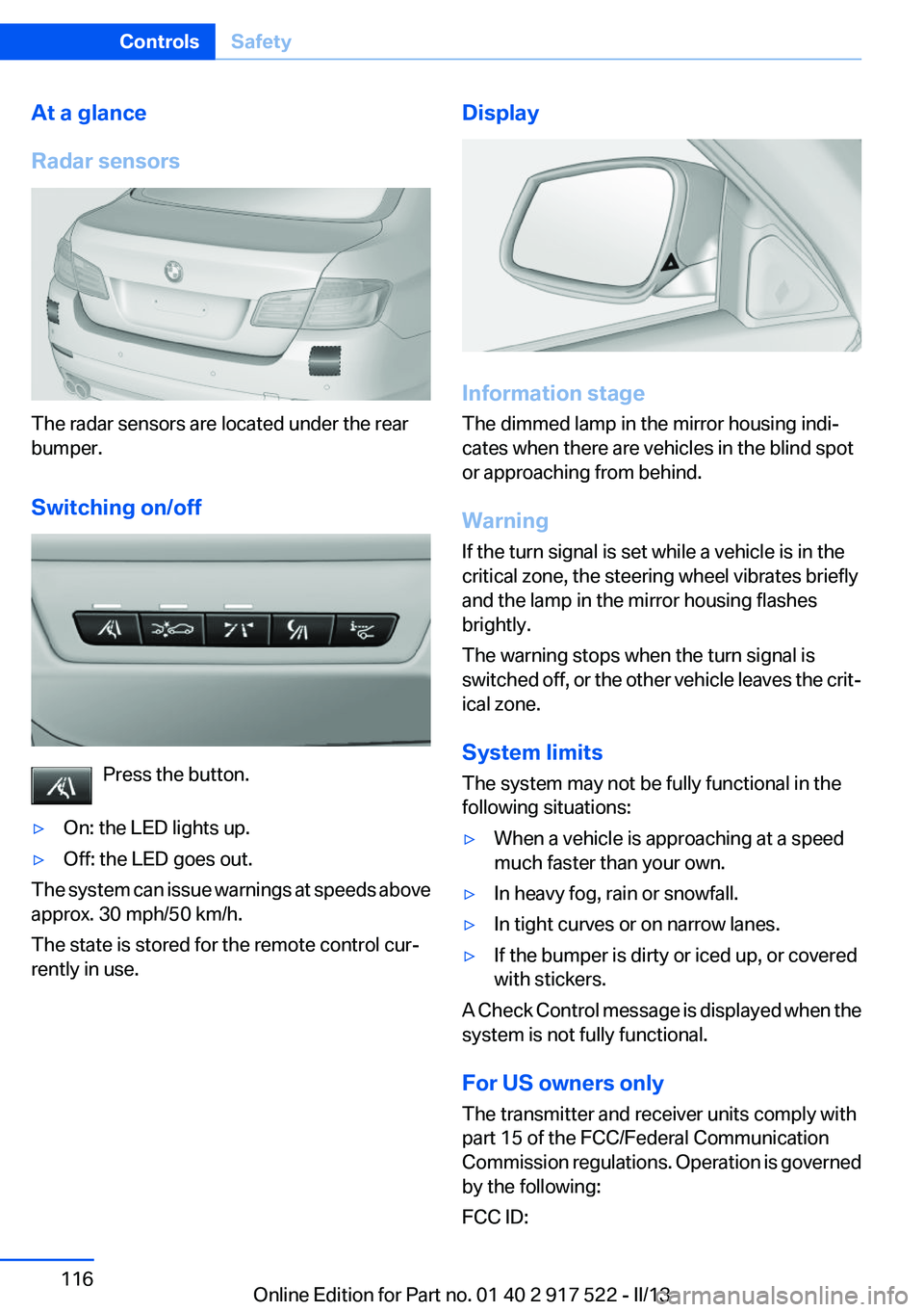
Two radar sensors below the rear bumper mon‐
itor the area behind and next to the vehicle at
speeds above approx. 30 mph/50 km/h.
The system indicates whether there are vehicles
in the blind spot, arrow 1, or approaching from
behind on the adjacent lane, arrow 2.
The lamp in the exterior mirror housing lights up
dimly.
Before you change lanes after setting the turn
signal, the system issues a warning in the situa‐
tions described above.
The lamp in the housing of the exterior mirror
flashes and the steering wheel vibrates.
Notes Personal responsibility
The system does not serve as a substitute
for the driver's personal judgment of the traffic
situation.
Be aware of the traffic situation and the vehicle's
surroundings at all times, otherwise an accident
is still possible despite all warnings.◀
Seite 115SafetyControls115
Online Edition for Part no. 01 40 2 917 522 - II/13
Page 116 of 246

At a glance
Radar sensors
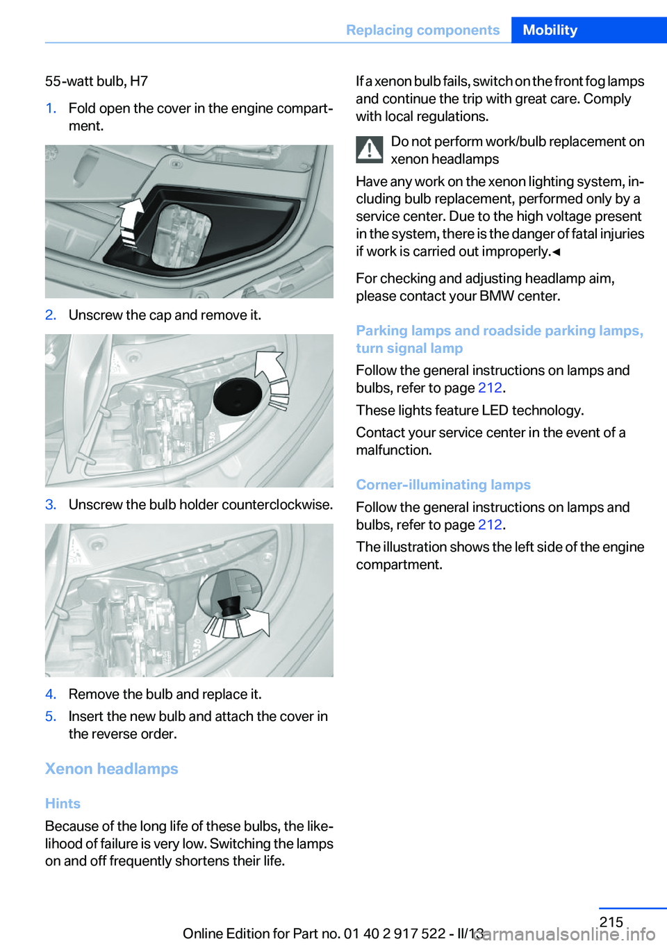
The radar sensors are located under the rear
bumper.
Switching on/off
Press the button.
▷On: the LED lights up.▷Off: the LED goes out.
The system can issue warnings at speeds above
approx. 30 mph/50 km/h.
The state is stored for the remote control cur‐
rently in use.
Display
Information stage
The dimmed lamp in the mirror housing indi‐
cates when there are vehicles in the blind spot
or approaching from behind.
Warning
If the turn signal is set while a vehicle is in the
critical zone, the steering wheel vibrates briefly
and the lamp in the mirror housing flashes
brightly.
The warning stops when the turn signal is
switched off, or the other vehicle leaves the crit‐
ical zone.
System limits
The system may not be fully functional in the
following situations:
▷When a vehicle is approaching at a speed
much faster than your own.▷In heavy fog, rain or snowfall.▷In tight curves or on narrow lanes.▷If the bumper is dirty or iced up, or covered
with stickers.
A Check Control message is displayed when the
system is not fully functional.
For US owners only
The transmitter and receiver units comply with
part 15 of the FCC/Federal Communication
Commission regulations. Operation is governed
by the following:
FCC ID:
Seite 116ControlsSafety116
Online Edition for Part no. 01 40 2 917 522 - II/13
Page 215 of 246

55-watt bulb, H71.Fold open the cover in the engine compart‐
ment.2.Unscrew the cap and remove it.3.Unscrew the bulb holder counterclockwise.4.Remove the bulb and replace it.5.Insert the new bulb and attach the cover in
the reverse order.
Xenon headlamps
Hints
Because of the long life of these bulbs, the like‐
lihood of failure is very low. Switching the lamps
on and off frequently shortens their life.
If a xenon bulb fails, switch on the front fog lamps
and continue the trip with great care. Comply
with local regulations.
Do not perform work/bulb replacement on
xenon headlamps
Have any work on the xenon lighting system, in‐
cluding bulb replacement, performed only by a
service center. Due to the high voltage present
in the system, there is the danger of fatal injuries
if work is carried out improperly.◀
For checking and adjusting headlamp aim,
please contact your BMW center.
Parking lamps and roadside parking lamps,
turn signal lamp
Follow the general instructions on lamps and
bulbs, refer to page 212.
These lights feature LED technology.
Contact your service center in the event of a
malfunction.
Corner-illuminating lamps
Follow the general instructions on lamps and
bulbs, refer to page 212.
The illustration shows the left side of the engine
compartment.Seite 215Replacing componentsMobility215
Online Edition for Part no. 01 40 2 917 522 - II/13