2013 BMW 535I XDRIVE GRAN TURISMO ECU
[x] Cancel search: ECUPage 79 of 240
P Park
Select only when the vehicle is stationary. The
drive wheels are blocked.
P is engaged automatically:▷After the engine is switched off when the
vehicle is in radio ready state, refer to
page 69, or when the ignition is switched off,
refer to page 68, and when position R or D is
engaged.▷With the ignition is off, if position N is en‐
gaged.▷If the safety belt is unbuckled, the driver's
door is opened, and the brake pedal is not
pressed while the vehicle is stationary and
transmission position R or D is engaged.
Before exiting the vehicle, make sure that posi‐
tion P of the automatic transmission is engaged.
Otherwise, the vehicle may begin to roll.
Kickdown
Kickdown is used to achieve maximum driving
performance. Press on the gas pedal beyond the
resistance point at the full throttle position.
Engaging the transmission position
▷Transmission position P can only be disen‐
gaged if the engine is running and the brake
pedal is pressed.▷With the vehicle stationary, press on the
brake pedal before shifting out of P or N;
otherwise, the shift command will not be
executed: shift lock.
Depress the brake until you start driv‐
ing
To prevent the vehicle from creeping after
you select a driving position, maintain pres‐
sure on the brake pedal until you are ready
to start.◀Engaging D, R and N
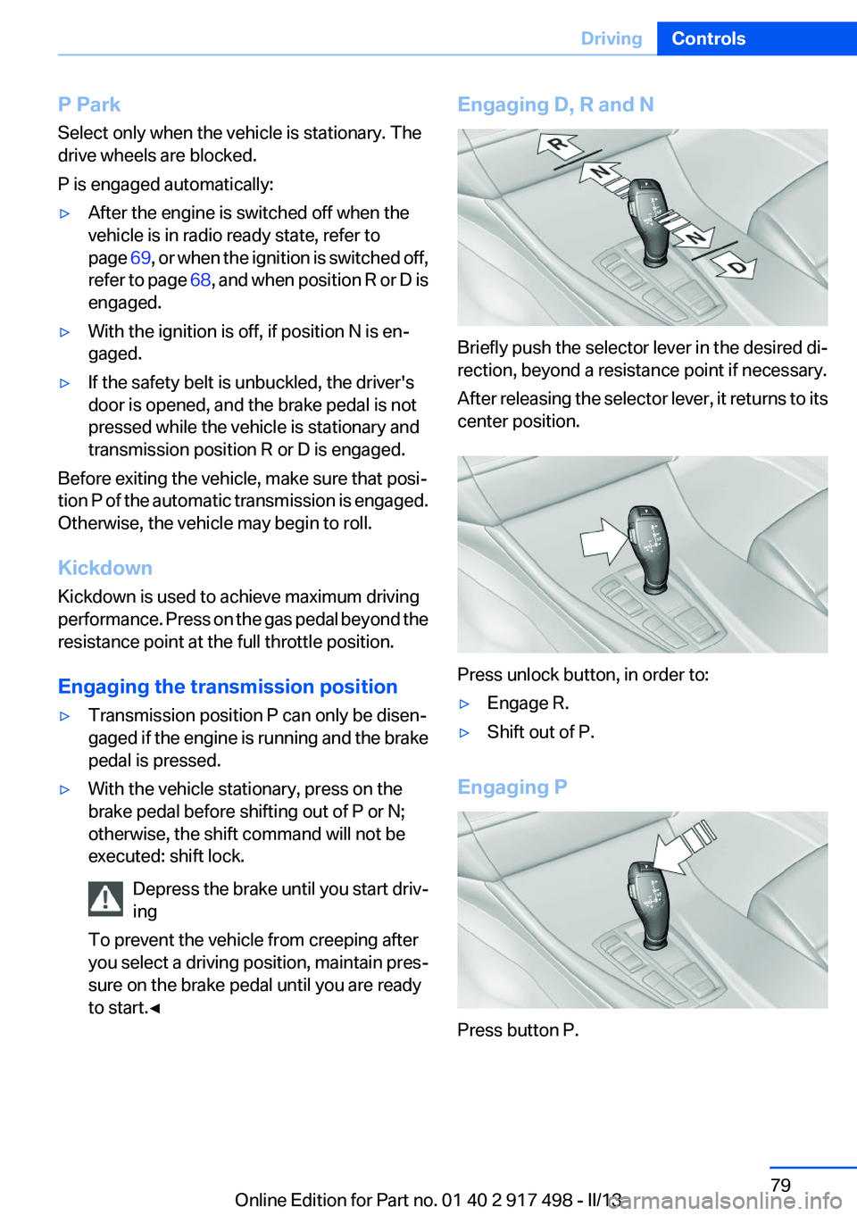
Briefly push the selector lever in the desired di‐
rection, beyond a resistance point if necessary.
After releasing the selector lever, it returns to its
center position.
Press unlock button, in order to:
▷Engage R.▷Shift out of P.
Engaging P
Press button P.
Seite 79DrivingControls79
Online Edition for Part no. 01 40 2 917 498 - II/13
Page 87 of 240
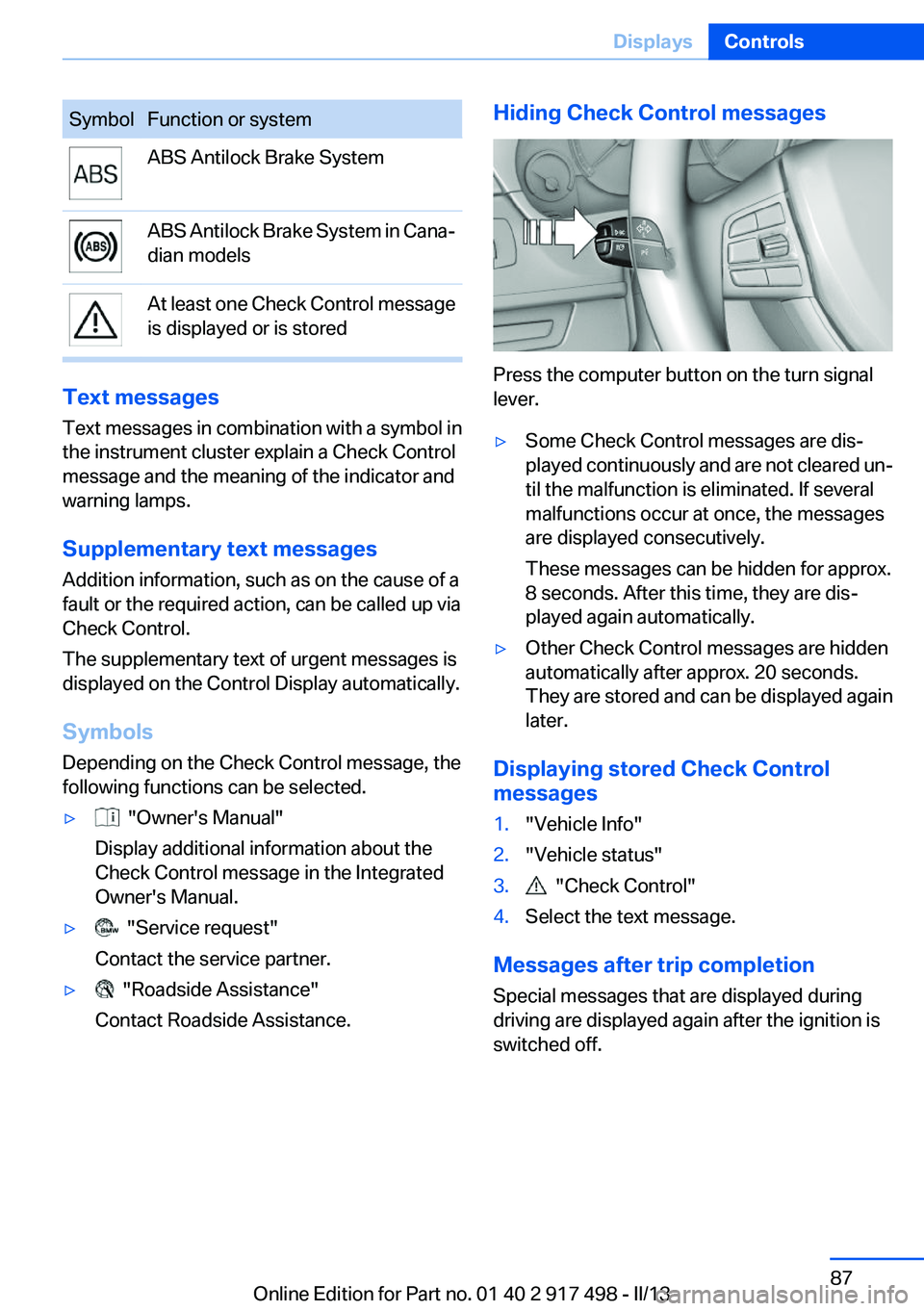
SymbolFunction or systemABS Antilock Brake SystemABS Antilock Brake System in Cana‐
dian modelsAt least one Check Control message
is displayed or is stored
Text messages
Text messages in combination with a symbol in
the instrument cluster explain a Check Control
message and the meaning of the indicator and
warning lamps.
Supplementary text messages
Addition information, such as on the cause of a
fault or the required action, can be called up via
Check Control.
The supplementary text of urgent messages is
displayed on the Control Display automatically.
Symbols
Depending on the Check Control message, the
following functions can be selected.
▷ "Owner's Manual"
Display additional information about the
Check Control message in the Integrated
Owner's Manual.▷ "Service request"
Contact the service partner.▷ "Roadside Assistance"
Contact Roadside Assistance.Hiding Check Control messages
Press the computer button on the turn signal
lever.
▷Some Check Control messages are dis‐
played continuously and are not cleared un‐
til the malfunction is eliminated. If several
malfunctions occur at once, the messages
are displayed consecutively.
These messages can be hidden for approx.
8 seconds. After this time, they are dis‐
played again automatically.▷Other Check Control messages are hidden
automatically after approx. 20 seconds.
They are stored and can be displayed again
later.
Displaying stored Check Control
messages
1."Vehicle Info"2."Vehicle status"3. "Check Control"4.Select the text message.
Messages after trip completion
Special messages that are displayed during
driving are displayed again after the ignition is
switched off.
Seite 87DisplaysControls87
Online Edition for Part no. 01 40 2 917 498 - II/13
Page 111 of 240
When the vehicle is intentionally brought into
contact with a vehicle, the collision warning is
delayed to avoid false warnings.
Switching on/off
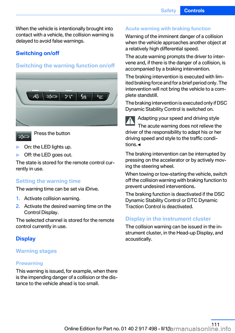
Switching the warning function on/off
Press the button
▷On: the LED lights up.▷Off: the LED goes out.
The state is stored for the remote control cur‐
rently in use.
Setting the warning time
The warning time can be set via iDrive.
1.Activate collision warning.2.Activate the desired warning time on the
Control Display.
The selected channel is stored for the remote
control currently in use.
Display
Warning stages
Prewarning
This warning is issued, for example, when there
is the impending danger of a collision or the dis‐
tance to the vehicle ahead is too small.
Acute warning with braking function
Warning of the imminent danger of a collision
when the vehicle approaches another object at
a relatively high differential speed.
The acute warning prompts the driver to inter‐
vene and, if there is the danger of a collision, is
accompanied by a braking intervention.
The braking intervention is executed with lim‐
ited braking force and for a brief period only. The
intervention will not bring the vehicle to a com‐
plete standstill.
The braking intervention is executed only if DSC
Dynamic Stability Control is switched on.
Adapting your speed and driving style
The acute warning does not relieve the
driver of the responsibility to adapt his or her
driving speed and style to the traffic condi‐
tions.◀
The braking intervention can be interrupted by
pressing on the accelerator or by actively mov‐
ing the steering wheel.
When towing or tow-starting the vehicle, switch
off the collision warning with braking function to
prevent undesired interventions.
The braking function is deactivated if the DSC
Dynamic Stability Control or DTC Dynamic
Traction Control is deactivated.
Display in the instrument cluster
The collision warning can be issued in the in‐
strument cluster, in the Head-up Display, and
acoustically.Seite 111SafetyControls111
Online Edition for Part no. 01 40 2 917 498 - II/13
Page 116 of 240
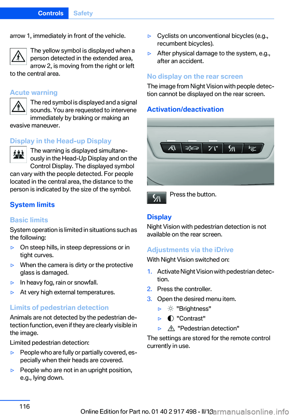
arrow 1, immediately in front of the vehicle.The yellow symbol is displayed when a
person detected in the extended area,
arrow 2, is moving from the right or left
to the central area.
Acute warning The red symbol is displayed and a signal
sounds. You are requested to intervene
immediately by braking or making an
evasive maneuver.
Display in the Head-up Display The warning is displayed simultane‐
ously in the Head-Up Display and on the
Control Display. The displayed symbol
can vary with the people detected. For people
located in the central area, the distance to the
person is indicated by the size of the symbol.
System limits
Basic limits
System operation is limited in situations such as
the following:▷On steep hills, in steep depressions or in
tight curves.▷When the camera is dirty or the protective
glass is damaged.▷In heavy fog, rain or snowfall.▷At very high external temperatures.
Limits of pedestrian detection
Animals are not detected by the pedestrian de‐
tection function, even if they are clearly visible in
the image.
Limited pedestrian detection:
▷People who are fully or partially covered, es‐
pecially when their heads are covered.▷People who are not in an upright position,
e.g., lying down.▷Cyclists on unconventional bicycles (e.g.,
recumbent bicycles).▷After physical damage to the system, e.g.,
after an accident.
No display on the rear screen
The image from Night Vision with people detec‐
tion cannot be displayed on the rear screen.
Activation/deactivation
Press the button.
Display
Night Vision with pedestrian detection is not
available on the rear screen.
Adjustments via the iDrive
With Night Vision switched on:
1.Activate Night Vision with pedestrian detec‐
tion.2.Press the controller.3.Open the desired menu item.▷ "Brightness"▷ "Contrast"▷ "Pedestrian detection"
The settings are stored for the remote control
currently in use.
Seite 116ControlsSafety116
Online Edition for Part no. 01 40 2 917 498 - II/13
Page 121 of 240
After a critical driving situation without an acci‐
dent, the front belts are loosened again. All other
systems can be restored to the desired setting.
If the belt tension does not loosen automatically,
stop the vehicle and unbuckle the belt using the
red button in the buckle. Fasten the belt before
continuing on your trip.
PostCrash
If an accident above a certain degree of severity,
the system automatically brakes the vehicle to a
standstill. This can reduce the risk of a further
collision and the consequences thereof.
Depressing the brake pedal can cause the vehi‐
cle to brake harder. This interrupts automatic
braking. Depressing the accelerator pedal also
interrupts automatic braking.
After coming to a halt, the brake is released au‐
tomatically. Secure the vehicle against rolling.Seite 121SafetyControls121
Online Edition for Part no. 01 40 2 917 498 - II/13
Page 133 of 240
While standingBefore leaving the vehicle, secure it
against rolling.
Before leaving the vehicle with the engine run‐
ning, engage position P of the automatic trans‐
mission and apply the parking brake. Otherwise,
the vehicle may begin to roll.◀
The system brought the vehicle to a complete
standstill:▷Green marking in the speedometer:
Your vehicle accelerates automatically as
soon as the vehicle in the range of the radar
sensor moves off.▷Marking in the speedometer turns orange:
no automatic driving away.
To accelerate to the desired speed auto‐
matically, press the accelerator briefly or
press the RES or SET button.
Rolling bars in the distance display indicate that
the vehicle in the radar sensor detection range
has moved off.
Your vehicle was braked to a halt by pressing on
the brake pedal and it is standing behind another
vehicle:
1. Press the button to call up a stored
desired speed.2.Release the brake pedal.3.Press on the accelerator briefly, or press the
RES button or the rocker switch when the
vehicle ahead of you drives away.
Displays in the instrument cluster
Desired speed
▷The marking lights up green:
the system is active.▷The marking lights up or‐
ange: the system has been
interrupted.▷The marking does not light up: the system is
switched off.
With instrument display: the symbol is
displayed in the speedometer similarly
to the mark for the desired speed.
Brief status display Selected desired speed.
If --- appears briefly on the display for Check
Control messages, it is possible that the system
requirements for operation are currently not
met.
Distance to vehicle ahead of you
The selected distance to the vehicle driving
ahead of you is shown.
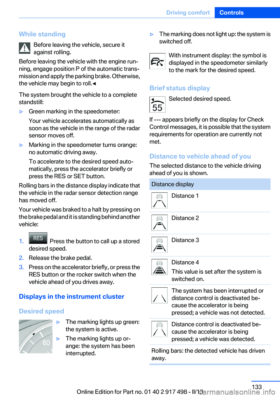
Distance displayDistance 1Distance 2Distance 3Distance 4
This value is set after the system is
switched on.The system has been interrupted or
distance control is deactivated be‐
cause the accelerator is being
pressed; a vehicle was not detected.Distance control is deactivated be‐
cause the accelerator is being
pressed; a vehicle was detected.Rolling bars: the detected vehicle has driven
away.Seite 133Driving comfortControls133
Online Edition for Part no. 01 40 2 917 498 - II/13
Page 159 of 240
Interior equipmentVehicle equipment
All standard, country-specific and optional
equipment that is offered in the model series is
described in this chapter. Therefore, equipment
is also described that is not available in a vehicle,
e. g., because of the selected optional equip‐
ment or country variant. This also applies for
safety-related functions and systems.
Integrated universal remote
control
The concept
The integrated universal remote control can op‐
erate up to 3 functions of remote-controlled sys‐
tems such as garage door drives or lighting sys‐
tems. The integrated universal remote control
replaces up to 3 different hand-held transmit‐
ters. To operate the remote control, the buttons
on the interior rearview mirror must be program‐
med with the desired functions. The hand-held
transmitter for the particular system is required
in order to program the remote control.
During programming
During programming and before activat‐
ing a device using the integrated universal re‐
mote control, ensure that there are no people,
animals, or objects in the range of movement of
the remote-controlled device; otherwise, there
is a risk of injury or damage.
Also follow the safety instructions of the hand-
held transmitter.◀
Before selling the vehicle, delete the stored
functions for the sake of security.
Compatibility If this symbol is printed on the packaging
or in the instructions of the system to be
controlled, the system is generally com‐patible with the integrated universal remote
control.
If you have any questions, please contact:▷Your service center.▷www.homelink.com on the Internet.
HomeLink is a registered trademark of Johnson
Controls, Inc.
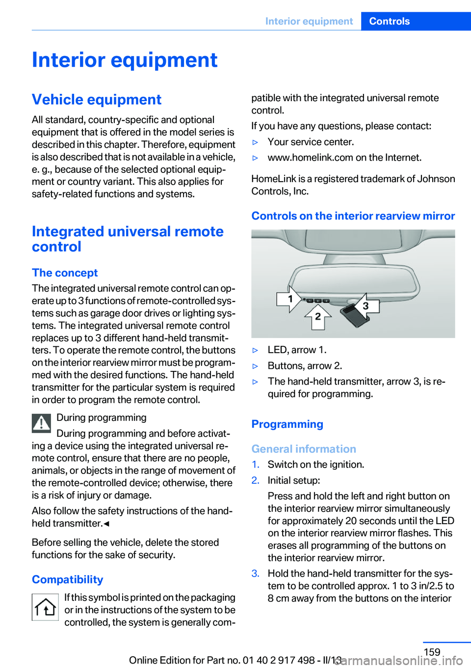
Controls on the interior rearview mirror
▷LED, arrow 1.▷Buttons, arrow 2.▷The hand-held transmitter, arrow 3, is re‐
quired for programming.
Programming
General information
1.Switch on the ignition.2.Initial setup:
Press and hold the left and right button on
the interior rearview mirror simultaneously
for approximately 20 seconds until the LED
on the interior rearview mirror flashes. This
erases all programming of the buttons on
the interior rearview mirror.3.Hold the hand-held transmitter for the sys‐
tem to be controlled approx. 1 to 3 in/2.5 to
8 cm away from the buttons on the interiorSeite 159Interior equipmentControls159
Online Edition for Part no. 01 40 2 917 498 - II/13
Page 164 of 240
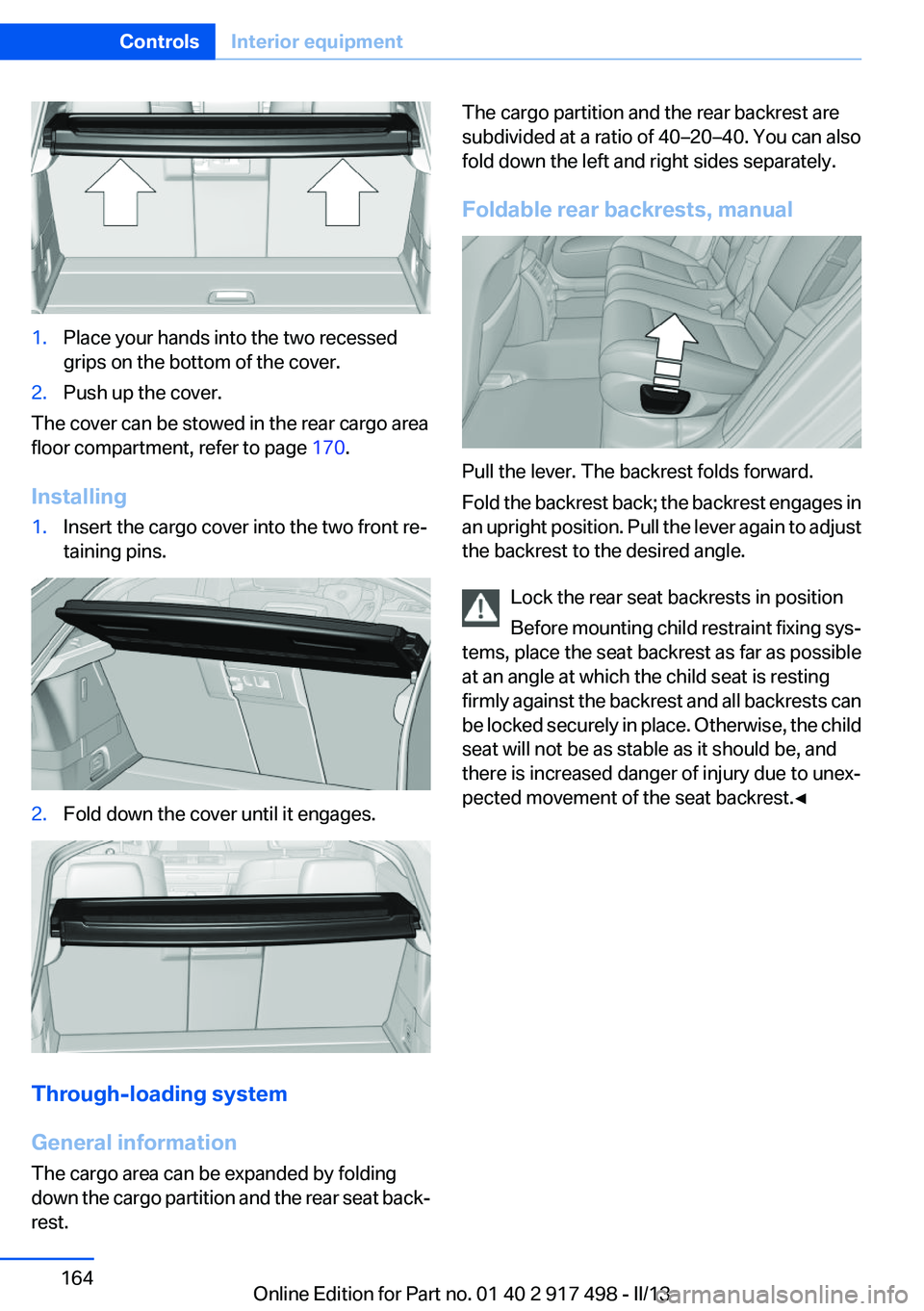
1.Place your hands into the two recessed
grips on the bottom of the cover.2.Push up the cover.
The cover can be stowed in the rear cargo area
floor compartment, refer to page 170.
Installing
1.Insert the cargo cover into the two front re‐
taining pins.2.Fold down the cover until it engages.
Through-loading system
General information
The cargo area can be expanded by folding
down the cargo partition and the rear seat back‐
rest.
The cargo partition and the rear backrest are
subdivided at a ratio of 40–20–40. You can also
fold down the left and right sides separately.
Foldable rear backrests, manual
Pull the lever. The backrest folds forward.
Fold the backrest back; the backrest engages in
an upright position. Pull the lever again to adjust
the backrest to the desired angle.
Lock the rear seat backrests in position
Before mounting child restraint fixing sys‐
tems, place the seat backrest as far as possible
at an angle at which the child seat is resting
firmly against the backrest and all backrests can
be locked securely in place. Otherwise, the child
seat will not be as stable as it should be, and
there is increased danger of injury due to unex‐
pected movement of the seat backrest.◀
Seite 164ControlsInterior equipment164
Online Edition for Part no. 01 40 2 917 498 - II/13