Page 161 of 246

middle section is folded down. Otherwise, injury
or damage may result.◀
Lock the rear seat backrests in position
Before mounting child restraint fixing sys‐
tems, place the seat backrest as far as possible
at an angle at which the child seat is resting
firmly against the backrest and all backrests can
be locked securely in place. Otherwise, the child
seat will not be as stable as it should be, and
there is increased danger of injury due to unex‐
pected movement of the seat backrest.◀
Opening Move the front seats to an upright position
Before folding down the rear backrests,
ensure that the front seats are moved forward
slightly and are in an upright position. Other‐
wise, the head restraint and screen could be
damaged.◀1.Unlock the belt lock of the center safety belt
in the rear using the latch plate of another
safety belt.2.Insert the latch plate at the end of the belt
into the specially designated fixture on the
rear window shelf.3.Push the corresponding head restraint
down as far as it will go.4.Pull the corresponding lever in the cargo
area to release the rear seat backrest.5.The unlocked rear seat backrest moves for‐
ward slightly.6.Fold backrest forward.
Closing
1.Return the rear seat backrest to the upright
seating position and engage it.
Ensure that the lock is securely en‐
gaged
Make sure that the lock engages properly
when folding back, otherwise transported
cargo could enter the passenger compart‐
ment during braking or evasive maneuvers
and endanger the vehicle occupants.◀2.Release the belt tongue from the fixture on
the rear window shelf.3.Insert the belt tongue in the belt lock of the
center safety belt. Make sure you hear the
latch plate engage.
To secure cargo, refer to page 176, with nets or
draw straps, the cargo area is fitted with lashing
eyes.
Seite 161Interior equipmentControls161
Online Edition for Part no. 01 40 2 917 522 - II/13
Page 165 of 246

Driver's side
Opening
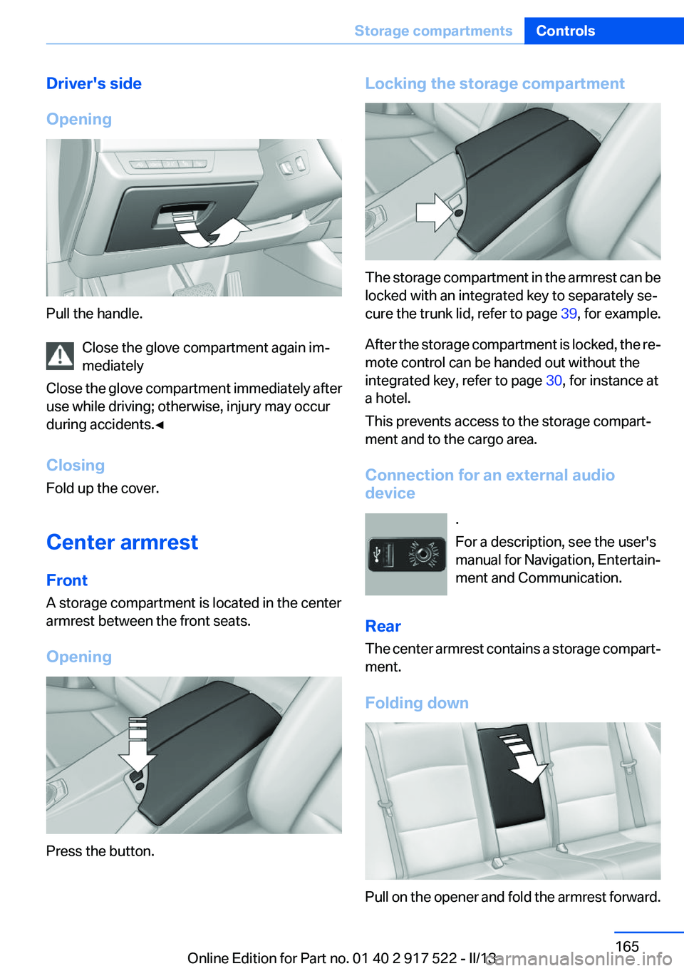
Pull the handle. Close the glove compartment again im‐
mediately
Close the glove compartment immediately after
use while driving; otherwise, injury may occur
during accidents.◀
Closing
Fold up the cover.
Center armrest
Front
A storage compartment is located in the center
armrest between the front seats.
Opening
Press the button.
Locking the storage compartment
The storage compartment in the armrest can be
locked with an integrated key to separately se‐
cure the trunk lid, refer to page 39, for example.
After the storage compartment is locked, the re‐
mote control can be handed out without the
integrated key, refer to page 30, for instance at
a hotel.
This prevents access to the storage compart‐
ment and to the cargo area.
Connection for an external audio
device
.
For a description, see the user's
manual for Navigation, Entertain‐
ment and Communication.
Rear
The center armrest contains a storage compart‐
ment.
Folding down
Pull on the opener and fold the armrest forward.
Seite 165Storage compartmentsControls165
Online Edition for Part no. 01 40 2 917 522 - II/13
Page 186 of 246

RefuelingVehicle equipment
All standard, country-specific and optional
equipment that is offered in the model series is
described in this chapter. Therefore, equipment
is also described that is not available in a vehicle,
e. g., because of the selected optional equip‐
ment or country variant. This also applies for
safety-related functions and systems.
General information Refuel promptly
Refuel no later than at a range of
30 miles/50 km, or operation of the engine is not
ensured and damage may occur.◀
Fuel cap
Opening1.Briefly press the rear edge of the fuel filler
flap.2.Turn the fuel cap counterclockwise.3.Place the fuel cap in the bracket attached to
the fuel filler flap.
Closing
1.Fit the cap and turn it clockwise until you
clearly hear a click.2.Close the fuel filler flap.
Do not pinch the retaining strap
Do not pinch the retaining strap attached
to the cap; otherwise, the cap cannot be closed
properly and fuel vapors can escape.
A message is displayed if the cap is loose or
missing.◀
Manually unlocking fuel filler flap
In the event of an electrical malfunction, for ex‐
ample.
Seite 186MobilityRefueling186
Online Edition for Part no. 01 40 2 917 522 - II/13
Page 205 of 246
Never reach into the engine compartment
Never reach into the intermediate spaces
or gaps in the engine compartment. Otherwise,
there is risk of injury, e.g. from rotating or hot
parts.◀1.Pull the lever.2.Press the release handle and open the hood.3.Be careful of protruding parts on the hood.
Danger of injury when the hood is open
There is a danger of injury from protruding
parts when the hood is open.◀
Closing the hood
Let the hood drop from a height of approx.
16 in/40 cm and push down on it to lock it fully.
The hood must audibly engage on both sides.
Hood open when driving
If you see any signs that the hood is not
completely closed while driving, pull over imme‐
diately and close it securely.◀
Danger of pinching
Make sure that the closing path of the
hood is clear; otherwise, injuries may result.◀
Seite 205Engine compartmentMobility205
Online Edition for Part no. 01 40 2 917 522 - II/13
Page 209 of 246

CoolantVehicle equipment
All standard, country-specific and optional
equipment that is offered in the model series is
described in this chapter. Therefore, equipment
is also described that is not available in a vehicle,
e. g., because of the selected optional equip‐
ment or country variant. This also applies for
safety-related functions and systems.
General information Danger of burns from hot engine
Do not open the cooling system while the
engine is hot; otherwise, escaping coolant may
cause burns.◀
Suitable additives
Only use suitable additives; otherwise, en‐
gine damage may occur. The additives are
harmful to your health.◀
Coolant consists of water and additives.
Not all commercially available additives are suit‐
able for your vehicle. Ask your service center for
suitable additives.
Coolant level
If there is no Min and Max mark in the filler neck
of the coolant reservoir, have the coolant level
checked if necessary by your service center and
add coolant as needed.
Note
Depending on the engine installation, the cool‐
ant reservoir may be located on the opposite
side of the engine compartment.Checking1.Let the engine cool.2.Turn the cap of the coolant reservoir slightly
counterclockwise to allow any excess pres‐
sure to dissipate, and then open it.3.The coolant level is correct if it lies between
the minimum and maximum marks in the
filler neck.4.If the coolant is low, slowly add coolant up to
the specified level; do not overfill.5.Turn the cap until there is an audible click.6.Have the cause of the coolant loss elimi‐
nated as soon as possible.
Disposal
Comply with the relevant environmental
protection regulations when disposing
of coolant and coolant additives.
Seite 209CoolantMobility209
Online Edition for Part no. 01 40 2 917 522 - II/13
Page 212 of 246

Replacing componentsVehicle equipment
All standard, country-specific and optional
equipment that is offered in the model series is
described in this chapter. Therefore, equipment
is also described that is not available in a vehicle,
e. g., because of the selected optional equip‐
ment or country variant. This also applies for
safety-related functions and systems.
Onboard vehicle tool kit
The onboard vehicle tool kit is located in a fold-
down cover in the trunk lid.
Unscrew the wing nut to open.
Wiper blade replacement
General information Do not fold down the wipers without wiper
blades
Do not fold down the wipers if wiper blades have
not been installed; this may damage the wind‐
shield.◀
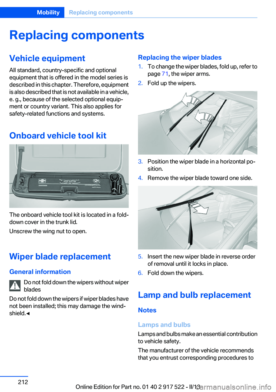
Replacing the wiper blades1.To change the wiper blades, fold up, refer to
page 71, the wiper arms.2.Fold up the wipers.3.Position the wiper blade in a horizontal po‐
sition.4.Remove the wiper blade toward one side.5.Insert the new wiper blade in reverse order
of removal until it locks in place.6.Fold down the wipers.
Lamp and bulb replacement
Notes
Lamps and bulbs
Lamps and bulbs make an essential contribution
to vehicle safety.
The manufacturer of the vehicle recommends
that you entrust corresponding procedures to
Seite 212MobilityReplacing components212
Online Edition for Part no. 01 40 2 917 522 - II/13
Page 215 of 246

55-watt bulb, H71.Fold open the cover in the engine compart‐
ment.2.Unscrew the cap and remove it.3.Unscrew the bulb holder counterclockwise.4.Remove the bulb and replace it.5.Insert the new bulb and attach the cover in
the reverse order.
Xenon headlamps
Hints
Because of the long life of these bulbs, the like‐
lihood of failure is very low. Switching the lamps
on and off frequently shortens their life.
If a xenon bulb fails, switch on the front fog lamps
and continue the trip with great care. Comply
with local regulations.
Do not perform work/bulb replacement on
xenon headlamps
Have any work on the xenon lighting system, in‐
cluding bulb replacement, performed only by a
service center. Due to the high voltage present
in the system, there is the danger of fatal injuries
if work is carried out improperly.◀
For checking and adjusting headlamp aim,
please contact your BMW center.
Parking lamps and roadside parking lamps,
turn signal lamp
Follow the general instructions on lamps and
bulbs, refer to page 212.
These lights feature LED technology.
Contact your service center in the event of a
malfunction.
Corner-illuminating lamps
Follow the general instructions on lamps and
bulbs, refer to page 212.
The illustration shows the left side of the engine
compartment.Seite 215Replacing componentsMobility215
Online Edition for Part no. 01 40 2 917 522 - II/13
Page 216 of 246
55-watt bulb, H71.Fold open the cover in the engine compart‐
ment.2.Unscrew the cap and remove it.3.Unscrew the bulb holder counterclockwise.4.Remove the bulb and replace it.5.Insert the new bulb and attach the cover in
the reverse order.
Front fog lamps
Follow the general instructions on lamps and
bulbs, refer to page 212.
35-watt bulb, H81.Carefully pull out the grill toward the front.2.Remove the screws.3.Pull the lamp out toward the front.4.Remove the bulb and replace it.5.Insert the new bulb and attach the cover in
the reverse order.
Tail lamps, bulb replacement
At a glance
1Turn signal2Reversing lamp3Inside brake lamp4Tail lampSeite 216MobilityReplacing components216
Online Edition for Part no. 01 40 2 917 522 - II/13