2013 BMW 335I steering
[x] Cancel search: steeringPage 112 of 242
Variable sport steering
The variable sport steering increases the steer‐
ing angle of the front wheels at large steering
wheel angles, e.g., in tight curves or when park‐
ing. Steering becomes more direct.
It also varies the force required to turn the
wheels in accordance with the vehicle speed.
This results in a sporty steering response. In ad‐
dition, it becomes easier to steer during parking
and maneuvering.
Driving Dynamics Control
The concept
The Driving Dynamics Control can be used to
adjust the certain characteristics of the vehicle.
Various programs can be selected for this pur‐
pose. The Driving Dynamics Control and the
DSC OFF buttons can each be used to activate
a program.
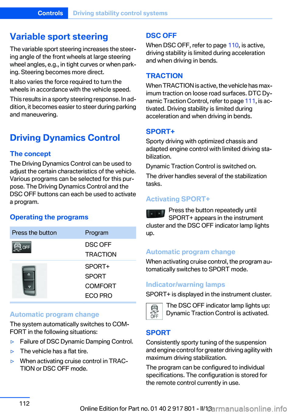
Operating the programsPress the buttonProgramDSC OFF
TRACTIONSPORT+
SPORT
COMFORT
ECO PRO
Automatic program change
The system automatically switches to COM‐
FORT in the following situations:
▷Failure of DSC Dynamic Damping Control.▷The vehicle has a flat tire.▷When activating cruise control in TRAC‐
TION or DSC OFF mode.DSC OFF
When DSC OFF, refer to page 110, is active,
driving stability is limited during acceleration
and when driving in bends.
TRACTION
When TRACTION is active, the vehicle has max‐
imum traction on loose road surfaces. DTC Dy‐
namic Traction Control, refer to page 111, is ac‐
tivated. Driving stability is limited during
acceleration and when driving in bends.
SPORT+
Sporty driving with optimized chassis and
adapted engine control with limited driving sta‐
bilization.
Dynamic Traction Control is switched on.
The driver handles several of the stabilization
tasks.
Activating SPORT+ Press the button repeatedly until
SPORT+ appears in the instrument
cluster and the DSC OFF indicator lamp lights
up.
Automatic program change
When activating cruise control, the program au‐
tomatically switches to SPORT mode.
Indicator/warning lamps
SPORT+ is displayed in the instrument cluster.
The DSC OFF indicator lamp lights up:
Dynamic Traction Control is activated.
SPORT
Consistently sporty tuning of the suspension
and engine control for greater driving agility with
maximum driving stabilization.
The program can be configured to individual
specifications. The configuration is stored for
the remote control currently in use.Seite 112ControlsDriving stability control systems112
Online Edition for Part no. 01 40 2 917 801 - II/13
Page 115 of 242

Driving comfortVehicle equipment
All standard, country-specific and optional
equipment that is offered in the model series is
described in this chapter. Therefore, equipment
is also described that is not available in a vehicle,
e. g., because of the selected optional equip‐
ment or country variant. This also applies for
safety-related functions and systems.
Active Cruise Control with
Stop & Go function, ACC
The concept
This system can be used to select a desired
speed that the vehicle will maintain automati‐
cally on clear roads.
To the extent possible, the system automatically
adjusts the speed to a slower vehicle ahead of
you.
The distance that the vehicle maintains to the
vehicle ahead of you can be varied.
For safety reasons, it depends on the speed.
To maintain a certain distance, the system au‐
tomatically decelerates, applies the brakes
lightly, or accelerates again if the vehicle ahead
begins moving faster.
If the vehicle ahead of you brakes to a halt, the
system is able to detect this within the given
system limits. If the vehicle ahead of your drives
away again from a halt, your vehicle is able to
accelerate if operated accordingly.
Even if some time passes before the vehicle
drives away again, the BMW can still be accel‐
erated automatically and simply.
As soon as the road is clear, it accelerates to the
desired speed.
The speed is also maintained on downhill gra‐
dients, but may not be maintained on uphill
slopes if engine power is insufficient.Notes
Personal responsibility
The system does not relieve the driver of
the responsibility to adapt his or her speed, dis‐
tance and driving style to the traffic conditions.
You should drive attentively and intervene ac‐
tively when necessary, e.g. by braking or making
an evasive maneuver, otherwise, there is danger
of an accident.◀
At a glance
Buttons on the steering wheel1System on/off, interrupt2Resume speed3Store speed4Reduce distance5Store, maintain/change speed6Increase distance
Radar sensor
A radar sensor is located in the front bumper for
detecting vehicles on the road ahead of the ve‐
hicle.
Seite 115Driving comfortControls115
Online Edition for Part no. 01 40 2 917 801 - II/13
Page 116 of 242
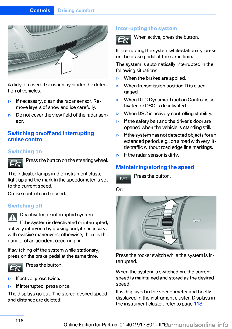
A dirty or covered sensor may hinder the detec‐
tion of vehicles.
▷If necessary, clean the radar sensor. Re‐
move layers of snow and ice carefully.▷Do not cover the view field of the radar sen‐
sor.
Switching on/off and interrupting
cruise control
Switching on Press the button on the steering wheel.
The indicator lamps in the instrument cluster
light up and the mark in the speedometer is set
to the current speed.
Cruise control can be used.
Switching off Deactivated or interrupted system
If the system is deactivated or interrupted,
actively intervene by braking and, if necessary,
with evasive maneuvers; otherwise, there is the
danger of an accident occurring.◀
If switching off the system while stationary,
press on the brake pedal at the same time.
Press the button.
▷If active: press twice.▷If interrupted: press once.
The displays go out. The stored desired speed
and distance are deleted.
Interrupting the system
When active, press the button.
If interrupting the system while stationary, press
on the brake pedal at the same time.
The system is automatically interrupted in the
following situations:▷When the brakes are applied.▷When transmission position D is disen‐
gaged.▷When DTC Dynamic Traction Control is ac‐
tivated or DSC is deactivated.▷When DSC is actively controlling stability.▷If the safety belt and the driver's door are
opened when the vehicle is standing still.▷If the system has not detected objects for an
extended period, e.g., on a road with very lit‐
tle traffic without road edge line markings.▷If the radar sensor is dirty.
Maintaining/storing the speed
Press the button.
Or:
Press the rocker switch while the system is in‐
terrupted.
When the system is switched on, the current
speed is maintained and stored as the desired
speed.
It is displayed in the speedometer and briefly
displayed in the instrument cluster, Displays in
the instrument cluster, refer to page 118.
Seite 116ControlsDriving comfort116
Online Edition for Part no. 01 40 2 917 801 - II/13
Page 121 of 242
Radar sensor
For US owners only
The transmitter and receiver units comply with
part 15 of the FCC/Federal Communication
Commission regulations. Operation is governed
by the following:
FCC ID:▷OAYARS3-A
Compliance statement:
This device complies with part 15 of the FCC
Rules. Operation is subject to the following two
conditions:
▷This device may not cause harmful interfer‐
ence, and▷this device must accept any interference re‐
ceived, including interference that may
cause undesired operation.
Any unauthorized modifications or changes to
these devices could void the user's authority to
operate this equipment.
Malfunction
The system cannot be activated if the radar sen‐
sor is not aligned correctly. This may be caused
by damage incurred during parking, for example.
A Check Control message is displayed if the
system fails.
Cruise control
The concept
The system is functional at speeds beginning at
approx. 20 mph/30 km/h.
It maintains the speed that was set using the
control elements on the steering wheel.
The system brakes on downhill gradients if en‐
gine braking action is insufficient.
Unfavorable conditions
Do not use the system if unfavorable con‐
ditions make it impossible to drive at a constant
speed, for instance:▷On curvy roads.▷In heavy traffic.▷On slippery roads, in fog, snow or rain, or on
a loose road surface.
Otherwise, you could lose control of the vehicle
and cause an accident.◀
Controls
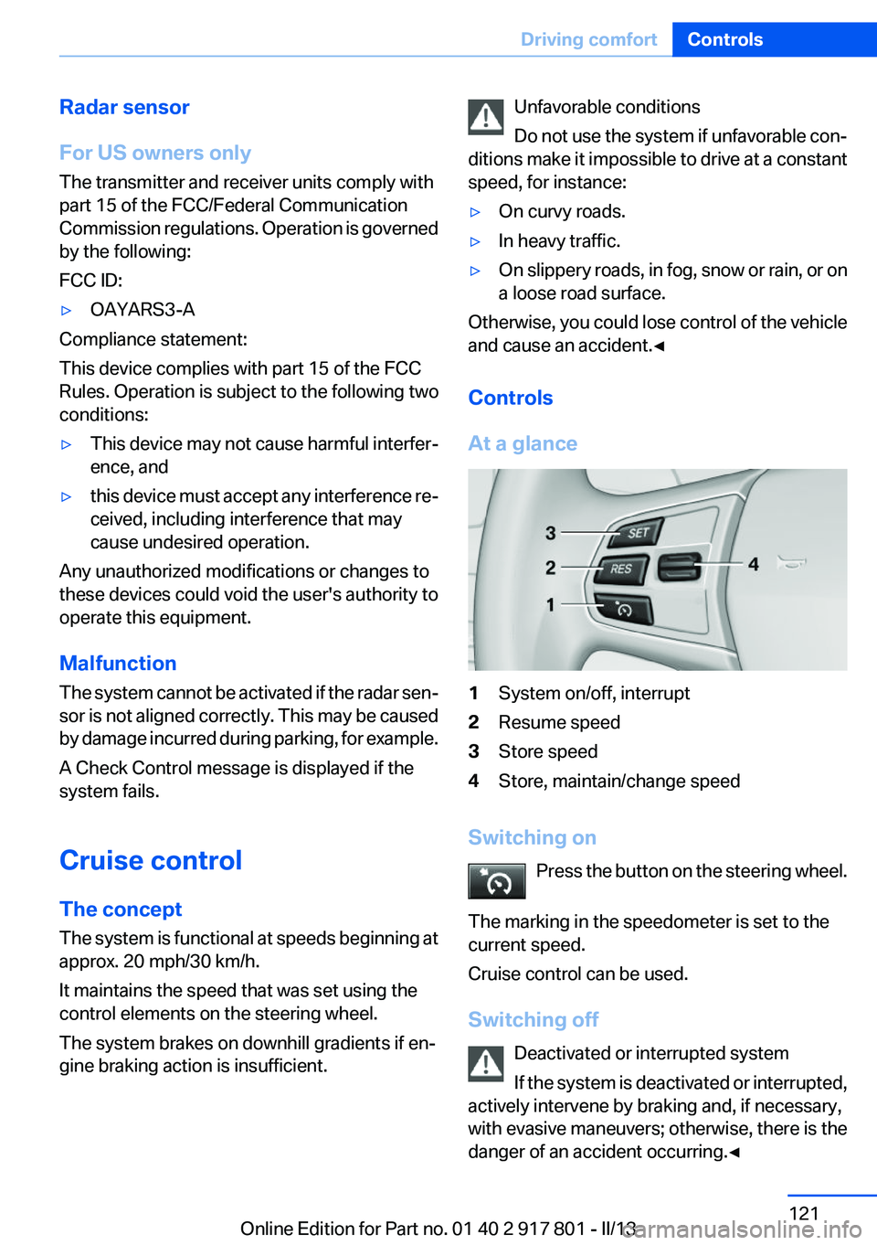
At a glance
1System on/off, interrupt2Resume speed3Store speed4Store, maintain/change speed
Switching on Press the button on the steering wheel.
The marking in the speedometer is set to the
current speed.
Cruise control can be used.
Switching off Deactivated or interrupted system
If the system is deactivated or interrupted,
actively intervene by braking and, if necessary,
with evasive maneuvers; otherwise, there is the
danger of an accident occurring.◀
Seite 121Driving comfortControls121
Online Edition for Part no. 01 40 2 917 801 - II/13
Page 127 of 242

Spatially-shaped markings are displayed.
Pathway lines
▷Can be shown in the backup camera image
when in transmission position R.▷Help you to estimate the space required
when parking and maneuvering on level
roads.▷Are dependent on the current steering angle
and are continuously adjusted to the steer‐
ing wheel movements.
Turning circle lines
▷Can be shown in the backup camera image.▷Show the course of the smallest possible
turning circle on a level road.▷Only one turning circle line is displayed
when the steering wheel is turned.Obstacle marking▷Spatially-shaped markings can be shown in
the backup camera image.
Their colored steps match the markings of the
PDC. This simplifies estimation of the distance
to the object shown.
Parking using pathway and turning
circle lines
1.Position the vehicle so that the turning circle
lines lead to within the limits of the parking
space.2.Turn the steering wheel to the point where
the pathway line covers the corresponding
turning circle line.Seite 127Driving comfortControls127
Online Edition for Part no. 01 40 2 917 801 - II/13
Page 129 of 242
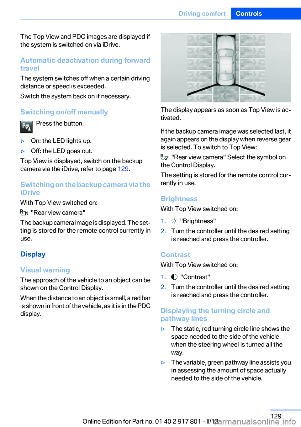
The Top View and PDC images are displayed if
the system is switched on via iDrive.
Automatic deactivation during forward
travel
The system switches off when a certain driving
distance or speed is exceeded.
Switch the system back on if necessary.
Switching on/off manually Press the button.▷On: the LED lights up.▷Off: the LED goes out.
Top View is displayed, switch on the backup
camera via the iDrive, refer to page 129.
Switching on the backup camera via the
iDrive
With Top View switched on:
"Rear view camera"
The backup camera image is displayed. The set‐
ting is stored for the remote control currently in
use.
Display
Visual warning
The approach of the vehicle to an object can be
shown on the Control Display.
When the distance to an object is small, a red bar
is shown in front of the vehicle, as it is in the PDC
display.
The display appears as soon as Top View is ac‐
tivated.
If the backup camera image was selected last, it
again appears on the display when reverse gear
is selected. To switch to Top View:
"Rear view camera" Select the symbol on
the Control Display.
The setting is stored for the remote control cur‐
rently in use.
Brightness
With Top View switched on:
1. "Brightness"2.Turn the controller until the desired setting
is reached and press the controller.
Contrast
With Top View switched on:
1. "Contrast"2.Turn the controller until the desired setting
is reached and press the controller.
Displaying the turning circle and
pathway lines
▷The static, red turning circle line shows the
space needed to the side of the vehicle
when the steering wheel is turned all the
way.▷The variable, green pathway line assists you
in assessing the amount of space actually
needed to the side of the vehicle.Seite 129Driving comfortControls129
Online Edition for Part no. 01 40 2 917 801 - II/13
Page 130 of 242
The pathway line is dependent on the cur‐
rent steering angle and is continuously ad‐
justed with the steering wheel movement.
"Parking aid lines"
Turning circle and pathway lines are displayed.
System limits
Top View cannot be used in the following situa‐
tions:
▷With a door open.▷With the trunk lid open.▷With an exterior mirror folded in.▷In poor light.
A Check Control message is displayed in some
of these situations.
Side View
The concept
Side View provides an early look at cross traffic
at blind driveways and intersections. Road users
concealed by obstacles to the left and right of
the vehicle can only be detected relatively late
from the driver's seat. To improve visibility, two
cameras in the front of the vehicle record the
traffic situation on each side.
Notes
The images from both cameras are shown si‐
multaneously on the Control Display.
Check the traffic situation as well
Check the traffic situation around the ve‐
hicle on blind driveways and intersections with
your own eyes. Otherwise, an accident could re‐
sult from road users or objects located outside
the picture area of the Side View cameras.◀
At a glance
Button in the vehicle
Side View
Cameras
Two cameras integrated in the bumpers capture
the image.
The two camera lenses are located on the sides
of the bumper.
The image quality may be impaired by dirt.
Clean the lens, refer to page 222.
Switching on/off
Switching on/off manually Press the button.
Automatic deactivation during forward
travel
The system switches off when a certain driving
distance or speed is exceeded.
Seite 130ControlsDriving comfort130
Online Edition for Part no. 01 40 2 917 801 - II/13
Page 132 of 242

▷Speed limit detection.▷Cruise control.▷Selection list from the instrument cluster.
Some of this information is only displayed briefly
as needed.
Selecting displays in the Head-up
Display
1."Settings"2."Head-up display"3."Displayed information"4.Select the desired displays in the Head-up
Display.
The settings are stored for the remote control
currently in use.
Setting the brightness
The brightness is automatically adjusted to the
ambient light.
The basic setting can be adjusted manually.
1."Settings"2."Head-up display"3."Brightness"4.Turn the controller.
When the low beams are switched on, the
brightness of the Head-up Display can be addi‐
tionally influenced using the instrument lighting.
The setting is stored for the remote control cur‐
rently in use.
Adjusting the height
1."Settings"2."Head-up display"3."Height"4.Turn the controller.
The setting is stored for the remote control cur‐
rently in use.
Setting the rotation1."Settings"2."Head-up display"3."Rotation"4.Turn the controller.
The setting is stored for the remote control cur‐
rently in use.
Special windshield
The windshield is part of the system.
The shape of the windshield makes it possible
to display a precise image.
A film in the windshield prevents double images
from being displayed.
Therefore, have the special windshield replaced
by a service center only.
Parking assistant
The concept
This system assists the driver in parking parallel
to the road.
Ultrasound sensors measure parking spaces on
both sides of the vehicle.
The parking assistant calculates the best pos‐
sible parking line and takes control of steering
during the parking procedure.
When parking, also take note of the visual and
acoustic information issued by the PDC and the
parking assistant and accelerate or brake ac‐
cordingly.
Seite 132ControlsDriving comfort132
Online Edition for Part no. 01 40 2 917 801 - II/13