2013 BMW 335I brake
[x] Cancel search: brakePage 121 of 242
Radar sensor
For US owners only
The transmitter and receiver units comply with
part 15 of the FCC/Federal Communication
Commission regulations. Operation is governed
by the following:
FCC ID:▷OAYARS3-A
Compliance statement:
This device complies with part 15 of the FCC
Rules. Operation is subject to the following two
conditions:
▷This device may not cause harmful interfer‐
ence, and▷this device must accept any interference re‐
ceived, including interference that may
cause undesired operation.
Any unauthorized modifications or changes to
these devices could void the user's authority to
operate this equipment.
Malfunction
The system cannot be activated if the radar sen‐
sor is not aligned correctly. This may be caused
by damage incurred during parking, for example.
A Check Control message is displayed if the
system fails.
Cruise control
The concept
The system is functional at speeds beginning at
approx. 20 mph/30 km/h.
It maintains the speed that was set using the
control elements on the steering wheel.
The system brakes on downhill gradients if en‐
gine braking action is insufficient.
Unfavorable conditions
Do not use the system if unfavorable con‐
ditions make it impossible to drive at a constant
speed, for instance:▷On curvy roads.▷In heavy traffic.▷On slippery roads, in fog, snow or rain, or on
a loose road surface.
Otherwise, you could lose control of the vehicle
and cause an accident.◀
Controls
At a glance
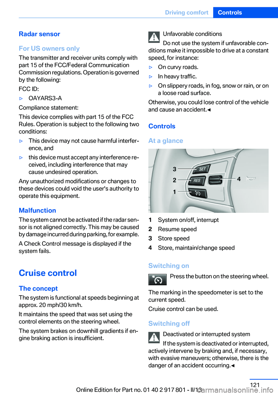
1System on/off, interrupt2Resume speed3Store speed4Store, maintain/change speed
Switching on Press the button on the steering wheel.
The marking in the speedometer is set to the
current speed.
Cruise control can be used.
Switching off Deactivated or interrupted system
If the system is deactivated or interrupted,
actively intervene by braking and, if necessary,
with evasive maneuvers; otherwise, there is the
danger of an accident occurring.◀
Seite 121Driving comfortControls121
Online Edition for Part no. 01 40 2 917 801 - II/13
Page 122 of 242
Press the button.▷If active: press twice.▷If interrupted: press once.
The displays go out. The stored desired speed
is deleted.
Interrupting the system When active, press the button.
The system is automatically interrupted if:
▷The brakes are applied.▷The clutch pedal is depressed for a few sec‐
onds or released while a gear is not en‐
gaged.▷The gear engaged is too high for the current
speed.▷The transmission position D is disengaged.▷DTC Dynamic Traction Control is activated
or DSC is deactivated.▷DSC is actively controlling stability.
Maintaining/storing the current speed
Press the button.
Or
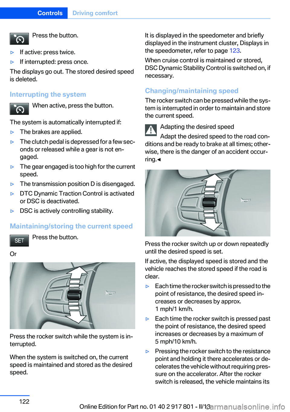
Press the rocker switch while the system is in‐
terrupted.
When the system is switched on, the current
speed is maintained and stored as the desired
speed.
It is displayed in the speedometer and briefly
displayed in the instrument cluster, Displays in
the speedometer, refer to page 123.
When cruise control is maintained or stored,
DSC Dynamic Stability Control is switched on, if
necessary.
Changing/maintaining speed
The rocker switch can be pressed while the sys‐
tem is interrupted in order to maintain and store
the current speed.
Adapting the desired speed
Adapt the desired speed to the road con‐
ditions and be ready to brake at all times; other‐
wise, there is the danger of an accident occur‐
ring.◀
Press the rocker switch up or down repeatedly
until the desired speed is set.
If active, the displayed speed is stored and the
vehicle reaches the stored speed if the road is
clear.
▷Each time the rocker switch is pressed to the
point of resistance, the desired speed in‐
creases or decreases by approx.
1 mph/1 km/h.▷Each time the rocker switch is pressed past
the point of resistance, the desired speed
increases or decreases by a maximum of
5 mph/10 km/h.▷Pressing the rocker switch to the resistance
point and holding it there accelerates or de‐
celerates the vehicle without requiring pres‐
sure on the accelerator. After the rocker
switch is released, the vehicle maintains itsSeite 122ControlsDriving comfort122
Online Edition for Part no. 01 40 2 917 801 - II/13
Page 132 of 242

▷Speed limit detection.▷Cruise control.▷Selection list from the instrument cluster.
Some of this information is only displayed briefly
as needed.
Selecting displays in the Head-up
Display
1."Settings"2."Head-up display"3."Displayed information"4.Select the desired displays in the Head-up
Display.
The settings are stored for the remote control
currently in use.
Setting the brightness
The brightness is automatically adjusted to the
ambient light.
The basic setting can be adjusted manually.
1."Settings"2."Head-up display"3."Brightness"4.Turn the controller.
When the low beams are switched on, the
brightness of the Head-up Display can be addi‐
tionally influenced using the instrument lighting.
The setting is stored for the remote control cur‐
rently in use.
Adjusting the height
1."Settings"2."Head-up display"3."Height"4.Turn the controller.
The setting is stored for the remote control cur‐
rently in use.
Setting the rotation1."Settings"2."Head-up display"3."Rotation"4.Turn the controller.
The setting is stored for the remote control cur‐
rently in use.
Special windshield
The windshield is part of the system.
The shape of the windshield makes it possible
to display a precise image.
A film in the windshield prevents double images
from being displayed.
Therefore, have the special windshield replaced
by a service center only.
Parking assistant
The concept
This system assists the driver in parking parallel
to the road.
Ultrasound sensors measure parking spaces on
both sides of the vehicle.
The parking assistant calculates the best pos‐
sible parking line and takes control of steering
during the parking procedure.
When parking, also take note of the visual and
acoustic information issued by the PDC and the
parking assistant and accelerate or brake ac‐
cordingly.
Seite 132ControlsDriving comfort132
Online Edition for Part no. 01 40 2 917 801 - II/13
Page 158 of 242
Things to remember when drivingVehicle equipment
All standard, country-specific and optional
equipment that is offered in the model series is
described in this chapter. Therefore, equipment
is also described that is not available in a vehicle,
e. g., because of the selected optional equip‐
ment or country variant. This also applies for
safety-related functions and systems.
Breaking-in period
General information
Moving parts need to be broken in to adjust to
each other.
The following instructions will help achieve a
long vehicle life and good economy.
Engine and differential
Always obey the official speed limit.
Up to 1,200 miles/2,000 km
Do not exceed the maximum engine and road
speed:▷For gasoline engine, 4,500 rpm and
100 mph/160 km/h.▷For diesel engine, 3,500 rpm and
93 mph/150 km/h.
Avoid full load or kickdown under all circum‐
stances.
From 1,200 miles/2,000 km
The engine and vehicle speed can gradually be
increased.
Tires
Due to technical factors associated with their
manufacture, tires do not achieve their full trac‐
tion potential until after an initial breaking-in pe‐
riod.
Drive conservatively for the first
200 miles/300 km.
Brake system
Brakes require an initial break-in period of ap‐
prox. 300 miles/500 km to achieve optimized
contact and wear patterns between brake discs
and brake pads. Drive moderately during this
break-in period.
Clutch
The function of the clutch reaches its optimal
level only after a distance driven of approx.
300 miles/500 km. During this break-in period,
engage the clutch gently.
Following part replacement
The same breaking in procedures should be ob‐
served if any of the components mentioned
above have to be renewed in the course of the
vehicle's operating life.
General driving notes
Closing the trunk lid Drive with the trunk lid closed
Only drive with the tailgate closed; other‐
wise, in the event of an accident or braking or
evasive maneuvers, passengers or other road
users may be injured or the vehicle may be dam‐
aged. In addition, exhaust fumes may enter the
passenger compartment.◀
If driving with the tailgate open cannot be
avoided:▷Close all windows and the glass sunroof.▷Greatly increase the blower speed.▷Drive moderately.Seite 158Driving tipsThings to remember when driving158
Online Edition for Part no. 01 40 2 917 801 - II/13
Page 159 of 242
Hot exhaust systemHot exhaust system
High temperatures are generated in the
exhaust system.
Do not remove the heat shields installed and
never apply undercoating to them. When driv‐
ing, standing at idle and while parking, take care
to avoid possible contact between the hot ex‐
haust system and any highly flammable materi‐
als such as hay, leaves, grass, etc. Such contact
could lead to a fire, and with it the risk of serious
personal injury as well as property damage.
Do not touch hot exhaust pipes; otherwise, there
is the danger of getting burned.◀
Diesel particulate filter
The diesel particulate filter collects soot parti‐
cles and burns them periodically at high tem‐
peratures.
During the cleaning time of several minutes, the
following may occur:▷Temporarily, the engine may run less
smoothly.▷Noises and a slight amount of smoke com‐
ing from the exhaust until shortly after the
engine is shut down.▷A somewhat higher engine speed is neces‐
sary to achieve the accustomed perform‐
ance.
Mobile communication devices in the
vehicle
Mobile communication devices in the ve‐
hicle
It is advised that you do not use mobile commu‐
nication devices, e.g., mobile phones, inside the
vehicle without connecting them directly to the
external antenna. Otherwise, the vehicle elec‐
tronics and mobile communication devices can
interfere with each other. In addition, there is no
assurance that the radiation generated during
transmission will be discharged from the vehicle
interior.◀
Hydroplaning
On wet or slushy roads, a wedge of water can
form between the tires and road surface.
This phenomenon is referred to as hydroplan‐
ing. It is characterized by a partial or complete
loss of contact between the tires and the road
surface, ultimately undermining your ability to
steer and brake the vehicle.
Hydroplaning
When driving on wet or slushy roads, re‐
duce your speed to prevent hydroplaning.◀
Driving through water
Drive though calm water only if it is not deeper
than 9.8 inches/25 cm and at this height, no
faster than walking speed, up to 6 mph/10 km/h.
Adhere to water depth and speed limita‐
tions
Do not exceed this water depth and walking
speed; otherwise, the vehicle's engine, the elec‐
trical systems and the transmission may be
damaged.◀
Braking safely
Your vehicle is equipped with ABS as a standard
feature.
Applying the brakes fully is the most effective
way of braking in situations when this is neces‐
sary.
The vehicle maintains steering responsiveness.
You can still avoid any obstacles with a minimum
of steering effort.
Pulsation of the brake pedal and sounds from
the hydraulic circuits indicate that ABS is in its
active mode.Seite 159Things to remember when drivingDriving tips159
Online Edition for Part no. 01 40 2 917 801 - II/13
Page 160 of 242
Objects in the area around the pedalsNo objects in the area around the pedals
Keep floor mats, carpets, and any other
objects out of the area of motion of the pedals;
otherwise, the function of the pedals could be
impeded while driving
Do not place additional floor mats over existing
mats or other objects.
Only use floor mats that have been approved for
the vehicle and can be properly fixed in place.
Ensure that the floor mats are securely fastened
again after they were removed for cleaning, for
example.◀
Driving in wet conditions
When roads are wet or there is heavy rain, briefly
exert gentle pressure on the brake pedal every
few miles.
Ensure that this action does not endanger other
road users.
The heat generated in this process helps dry the
brake discs and pads.
In this way braking efficiency will be available
when you need it.
Hills
Drive long or steep downhill gradients in the gear
in which the least braking is required. Otherwise,
the brake system may overheat, resulting in a
reduction in the brake system efficiency.
You can increase the engine's braking effect by
shifting down, going all the way to first gear, if
necessary.
Avoid load on the brakes
Avoid placing excessive load on the brake
system. Light but consistent brake pressure can
lead to high temperatures, brake wear and pos‐
sibly even brake failure.◀Do not drive in neutral
Do not drive in neutral or with the engine
stopped, as doing so disables engine braking. In
addition, steering and brake assist is unavailable
with the engine stopped.◀
Brake disc corrosion
Corrosion on the brake discs and contamination
on the brake pads are furthered by:▷Low mileage.▷Extended periods when the vehicle is not
used at all.▷Infrequent use of the brakes.
Corrosion occurs when the minimum pressure
that must be exerted by the pads during brake
applications to clean the discs is not reached.
Should corrosion form on the brake discs, the
brakes will tend to respond with a pulsating ef‐
fect that generally cannot be corrected.
Condensation under the parked vehicle
When using the automatic climate control, con‐
densation water develops that exits underneath
the vehicle.
Traces of water under the vehicle like this are
normal.
Seite 160Driving tipsThings to remember when driving160
Online Edition for Part no. 01 40 2 917 801 - II/13
Page 200 of 242
MaintenanceVehicle equipment
All standard, country-specific and optional
equipment that is offered in the model series is
described in this chapter. Therefore, equipment
is also described that is not available in a vehicle,
e. g., because of the selected optional equip‐
ment or country variant. This also applies for
safety-related functions and systems.
BMW Maintenance System
The maintenance system directs you to re‐
quired maintenance measures and thereby sup‐
ports you in maintaining road safety and the op‐
erational reliability of the vehicle.
Condition Based Service CBS
Sensors and special algorithms take into ac‐
count the driving conditions of your vehicle.
Based on this, Condition Based Service deter‐
mines the maintenance requirements.
The system makes it possible to adapt the
amount of maintenance you need to your user
profile.
Detailed information on service requirements,
refer to page 77, can be displayed on the Control
Display.
Service data in the remote control
Information on the required maintenance is con‐
tinuously stored in the remote control. Your
service center will read out this data and suggest
the right array of service procedures for your ve‐
hicle.
Therefore, hand your service specialist the re‐
mote control that you used most recently.Storage periods
Storage periods during which the vehicle bat‐
tery was disconnected are not taken into ac‐
count.
If this occurs, have a service center update the
time-dependent maintenance procedures,
such as checking brake fluid and, if necessary,
changing the engine oil and the microfilter/acti‐
vated-charcoal filter.
Service history
Perform maintenance work at the service center
and have them recorded in the vehicle data. The
entries are like a service booklet of the docu‐
mentation of regular maintenance.
Displaying entered maintenance work on the
Control Display, refer to page 78.
Service and Warranty
Information Booklet for US
models and Warranty and
Service Guide Booklet for
Canadian models
Please consult your Service and Warranty Infor‐
mation Booklet for US models and Warranty and
Service Guide Booklet for Canadian models for
additional information on service requirements.
Maintenance and repair should be performed by
your service center. Make sure to have regular
maintenance procedures recorded in the vehi‐
cle's Service and Warranty Information Booklet
for US models, and in the Warranty and Service
Guide Booklet for Canadian models. These en‐
tries are proof of regular maintenance.Seite 200MobilityMaintenance200
Online Edition for Part no. 01 40 2 917 801 - II/13
Page 208 of 242
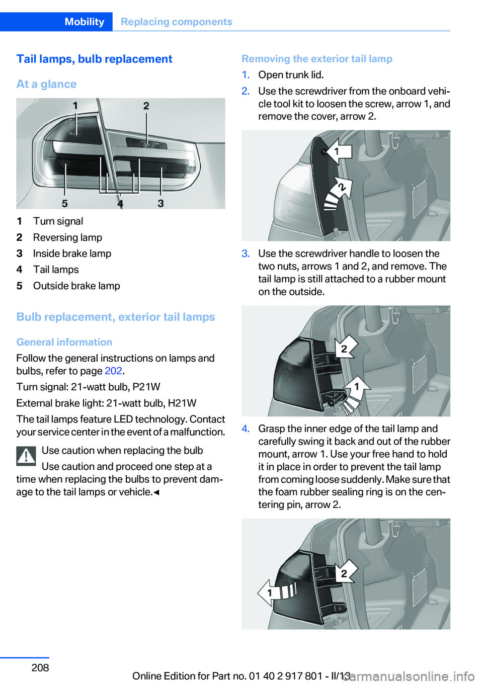
Tail lamps, bulb replacement
At a glance1Turn signal2Reversing lamp3Inside brake lamp4Tail lamps5Outside brake lamp
Bulb replacement, exterior tail lamps
General information
Follow the general instructions on lamps and
bulbs, refer to page 202.
Turn signal: 21-watt bulb, P21W
External brake light: 21-watt bulb, H21W
The tail lamps feature LED technology. Contact
your service center in the event of a malfunction.
Use caution when replacing the bulb
Use caution and proceed one step at a
time when replacing the bulbs to prevent dam‐
age to the tail lamps or vehicle.◀
Removing the exterior tail lamp1.Open trunk lid.2.Use the screwdriver from the onboard vehi‐
cle tool kit to loosen the screw, arrow 1, and
remove the cover, arrow 2.3.Use the screwdriver handle to loosen the
two nuts, arrows 1 and 2, and remove. The
tail lamp is still attached to a rubber mount
on the outside.4.Grasp the inner edge of the tail lamp and
carefully swing it back and out of the rubber
mount, arrow 1. Use your free hand to hold
it in place in order to prevent the tail lamp
from coming loose suddenly. Make sure that
the foam rubber sealing ring is on the cen‐
tering pin, arrow 2.Seite 208MobilityReplacing components208
Online Edition for Part no. 01 40 2 917 801 - II/13