2013 BMW 335I tow
[x] Cancel search: towPage 153 of 242
Front passenger side
Opening
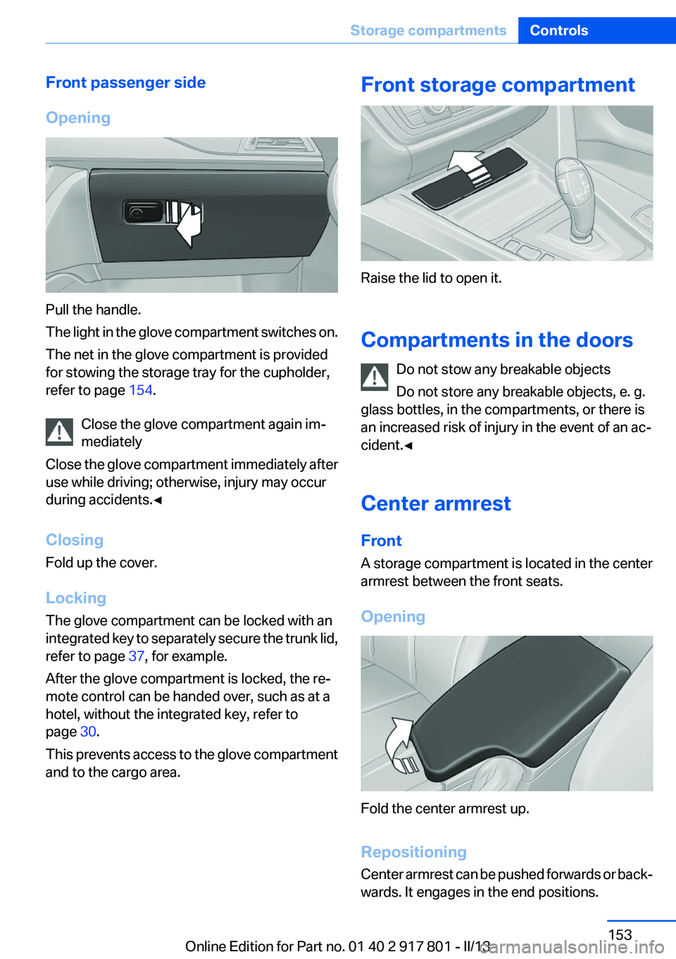
Pull the handle.
The light in the glove compartment switches on.
The net in the glove compartment is provided
for stowing the storage tray for the cupholder,
refer to page 154.
Close the glove compartment again im‐
mediately
Close the glove compartment immediately after
use while driving; otherwise, injury may occur
during accidents.◀
Closing
Fold up the cover.
Locking
The glove compartment can be locked with an
integrated key to separately secure the trunk lid,
refer to page 37, for example.
After the glove compartment is locked, the re‐
mote control can be handed over, such as at a
hotel, without the integrated key, refer to
page 30.
This prevents access to the glove compartment
and to the cargo area.
Front storage compartment
Raise the lid to open it.
Compartments in the doors Do not stow any breakable objects
Do not store any breakable objects, e. g.
glass bottles, in the compartments, or there is
an increased risk of injury in the event of an ac‐
cident.◀
Center armrest
Front
A storage compartment is located in the center
armrest between the front seats.
Opening
Fold the center armrest up.
Repositioning
Center armrest can be pushed forwards or back‐
wards. It engages in the end positions.
Seite 153Storage compartmentsControls153
Online Edition for Part no. 01 40 2 917 801 - II/13
Page 154 of 242
Connection for an external audio
device
.
For a description, see the user's
manual for Navigation, Entertain‐
ment and Communication.
Storage compartment in the
rear
Storage compartment is located in the rear cen‐
ter console.
Cupholders
Notes Shatter-proof containers and no hot
drinks
Use light and shatter-proof containers and do
not transport hot drinks. Otherwise, there is the
increased danger of injury in an accident.◀
Unsuitable containers
Do not forcefully push unsuitable contain‐
ers into the cupholders. This may result in dam‐
age.◀
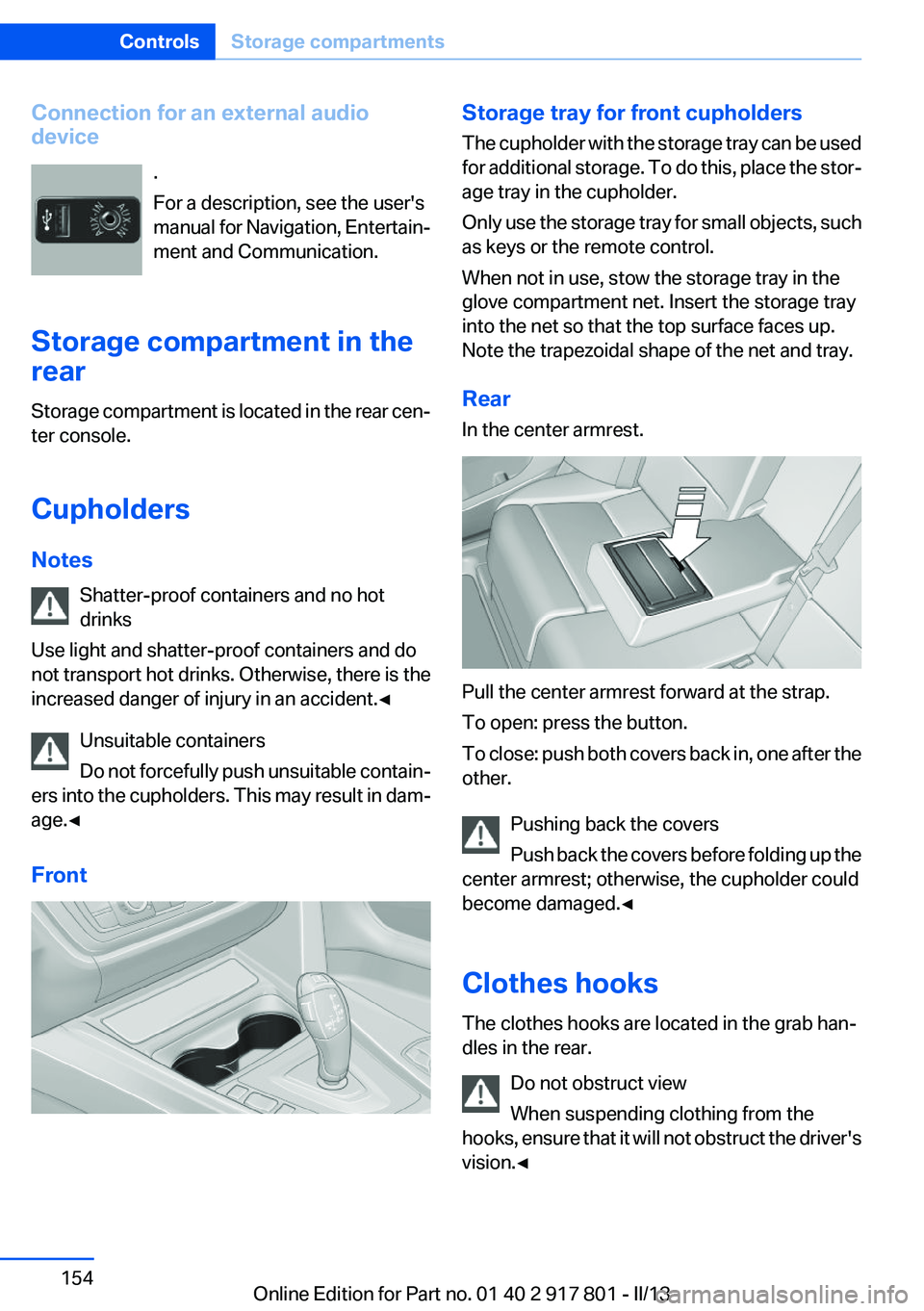
FrontStorage tray for front cupholders
The cupholder with the storage tray can be used
for additional storage. To do this, place the stor‐
age tray in the cupholder.
Only use the storage tray for small objects, such
as keys or the remote control.
When not in use, stow the storage tray in the
glove compartment net. Insert the storage tray
into the net so that the top surface faces up.
Note the trapezoidal shape of the net and tray.
Rear
In the center armrest.
Pull the center armrest forward at the strap.
To open: press the button.
To close: push both covers back in, one after the
other.
Pushing back the covers
Push back the covers before folding up the
center armrest; otherwise, the cupholder could
become damaged.◀
Clothes hooks
The clothes hooks are located in the grab han‐
dles in the rear.
Do not obstruct view
When suspending clothing from the
hooks, ensure that it will not obstruct the driver's
vision.◀
Seite 154ControlsStorage compartments154
Online Edition for Part no. 01 40 2 917 801 - II/13
Page 155 of 242
No heavy objects
Do not hang heavy objects from the hooks;
otherwise, they may present a danger to pas‐
sengers during braking and evasive maneu‐
vers.◀
Storage compartments in the
cargo area
Storage compartment
A storage compartment is located on the left
side.
Located on the right side is a storage compart‐
ment for the onboard vehicle tool kit, refer to
page 202, and first aid kit, refer to page 214.
Net
Small objects can be stowed in the net on the
left side.
Hooks/multi-function hook
A multi-function hook is located on each side of
the cargo area. The multi-function hooks can be
loaded up to a max. of 8.8 lbs/4 kg.
Light and suitable objects only
Only hang light bags or suitable objects
from the holders. Otherwise, there is a danger of
objects flying about during braking and evasive
maneuvers.
Only transport heavy luggage in the trunk if it has
been appropriately secured.◀
Retaining strap
A retaining strap is available on the right side trim
for fastening small objects.
Lashing eyes in the cargo area
To secure the cargo, refer to page 162, there
are four lashing eyes in the cargo area.
Floor net
The floor net can also be used to Secure the
load, refer to page 162, and to store small parts.
Storage compartment under cargo
floor panel
Maximum load
To avoid damage to the vehicle, do not ex‐
ceed a maximum permitted load of 44 lbs/20 kg
in the storage compartment under the cargo
floor panel.◀
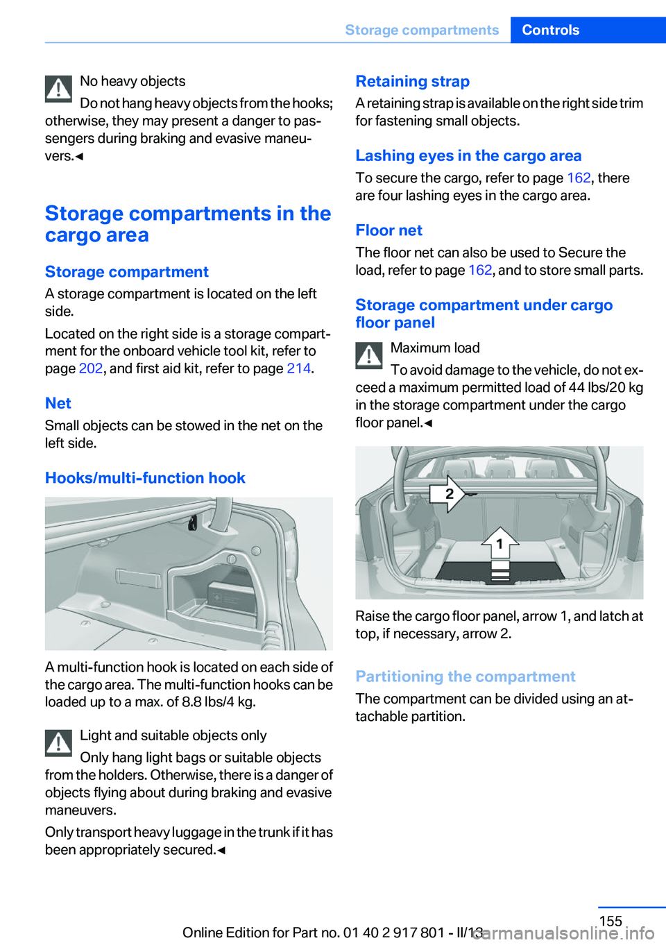
Raise the cargo floor panel, arrow 1, and latch at
top, if necessary, arrow 2.
Partitioning the compartment
The compartment can be divided using an at‐
tachable partition.
Seite 155Storage compartmentsControls155
Online Edition for Part no. 01 40 2 917 801 - II/13
Page 162 of 242
Stowing cargo▷Cover sharp edges and corners on the
cargo.▷Heavy cargo: stow as far forward as possi‐
ble, directly behind and at the bottom of the
rear passenger seat backrests.▷Very heavy cargo: when the rear seat is not
occupied, secure each of the outer safety
belts in the opposite buckle.▷If necessary, fold down the rear backrests to
stow cargo.▷Do not stack cargo above the top edge of the
backrests.
Securing cargo
Lashing eyes in the cargo area
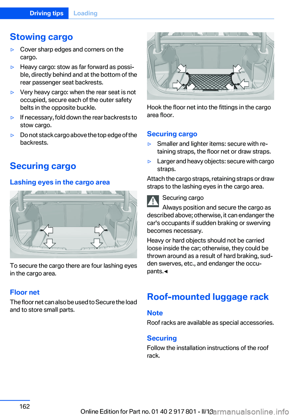
To secure the cargo there are four lashing eyes
in the cargo area.
Floor net
The floor net can also be used to Secure the load
and to store small parts.
Hook the floor net into the fittings in the cargo
area floor.
Securing cargo
▷Smaller and lighter items: secure with re‐
taining straps, the floor net or draw straps.▷Larger and heavy objects: secure with cargo
straps.
Attach the cargo straps, retaining straps or draw
straps to the lashing eyes in the cargo area.
Securing cargo
Always position and secure the cargo as
described above; otherwise, it can endanger the
car's occupants if sudden braking or swerving
becomes necessary.
Heavy or hard objects should not be carried
loose inside the car; otherwise, they could be
thrown around as a result of hard braking, sud‐
den swerves, etc., and endanger the occu‐
pants.◀
Roof-mounted luggage rack
Note
Roof racks are available as special accessories.
Securing
Follow the installation instructions of the roof
rack.
Seite 162Driving tipsLoading162
Online Edition for Part no. 01 40 2 917 801 - II/13
Page 190 of 242
ces of asphalt and concrete. A tire marked C may
have poor traction performance.
The traction grade assigned to this tire is based
on straight-ahead braking traction tests, and
does not include acceleration, cornering, hydro‐
planing, or peak traction characteristics.
Temperature
The temperature grades are A, the highest, B,
and C, representing the tire's resistance to the
generation of heat and its ability to dissipate
heat when tested under controlled conditions
on a specified indoor laboratory test wheel. Sus‐
tained high temperature can cause the material
of the tire to degenerate and reduce tire life, and
excessive temperature can lead to sudden tire
failure. The grade C corresponds to a level of
performance which all passenger car tires must
meet under the Federal Motor Vehicle Safety
Standard No. 109. Grades Band A represent
higher levels of performance on the laboratory
test wheel than the minimum required by law.
Temperature grade for this tire
The temperature grade for this tire is es‐
tablished for a tire that is properly inflated and
not overloaded. Excessive speed, underinfla‐
tion, or excessive loading, either separately or in
combination, can cause heat buildup and pos‐
sible tire failure.
If necessary, have the vehicle towed.◀
RSC – Run-flat tires
Run-flat tires, refer to page 192, are labeled with
a circular symbol containing the letters RSC
marked on the sidewall.
M+S
Winter and all-season tires with better cold
weather performance than summer tires.Tire tread
Summer tires
Do not drive with a tire tread depth of less than
0.12 in/3 mm.
There is an increased danger of hydroplaning if
the tread depth is less than 0.12 in/3 mm.
Winter tires
Do not drive with a tire tread depth of less than
0.16 in/4 mm.
Below a tread depth of 0.16 in/4 mm, tires are
less suitable for winter operation.
Minimum tread depth
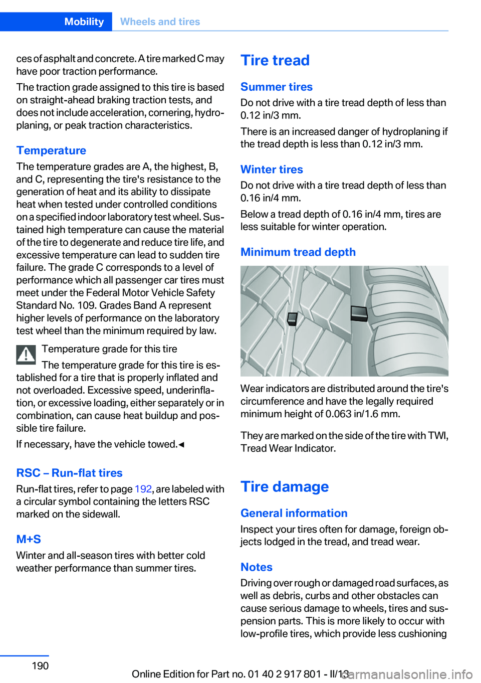
Wear indicators are distributed around the tire's
circumference and have the legally required
minimum height of 0.063 in/1.6 mm.
They are marked on the side of the tire with TWI,
Tread Wear Indicator.
Tire damage
General information
Inspect your tires often for damage, foreign ob‐
jects lodged in the tread, and tread wear.
Notes
Driving over rough or damaged road surfaces, as
well as debris, curbs and other obstacles can
cause serious damage to wheels, tires and sus‐
pension parts. This is more likely to occur with
low-profile tires, which provide less cushioning
Seite 190MobilityWheels and tires190
Online Edition for Part no. 01 40 2 917 801 - II/13
Page 191 of 242
between the wheel and the road. Be careful to
avoid road hazards and reduce your speed, es‐
pecially if your vehicle is equipped with low-pro‐
file tires.
Indications of tire damage or other vehicle de‐
fects:▷Unusual vibrations during driving.▷Unusual handling such as a strong tendency
to pull to the left or right.
Damage can, e. g., be caused by driving over
curbs, road damage, or similar things.
In case of tire damage
If there are indications of tire damage, re‐
duce your speed immediately and have the
wheels and tires checked right away; otherwise,
there is the increased risk of an accident.
Drive carefully to the next service center or tire
shop.
If necessary, have the vehicle towed.
Otherwise, tire damage can be life-threatening
for vehicle occupants and other traffic partici‐
pants.◀
Repair of tire damage
For safety reasons, the manufacturer of
your vehicle recommends that you do not have
damaged tires repaired; they should be re‐
placed. Otherwise, damage can occur as a re‐
sult.◀
Changing wheels and tires
Mounting Information on mounting tires
Have mounting and balancing performed
only by a service center or tire specialist.
If this work is not carried out properly, there is
the danger of subsequent damage and related
safety hazards.◀
Wheel and tire combination
Information on the correct wheel-tire combina‐
tion and rim versions for your vehicle can be ob‐
tained from your service center.
Incorrect wheel and tire combinations impair the
function of a variety of systems such as ABS or
DSC.
To maintain good handling and vehicle re‐
sponse, use only tires with a single tread con‐
figuration from a single manufacturer.
Following tire damage, have the original wheel
and tire combination remounted on the vehicle
as soon as possible.
Approved wheels and tires
The manufacturer of your vehicle recom‐
mends that you use only wheels and tires that
have been approved for your particular vehicle
model.
For example, despite having the same official
size ratings, variations can lead to body contact
and with it, the risk of severe accidents.
The manufacturer of your vehicle cannot evalu‐
ate non-approved wheels and tires to determine
if they are suited for use, and therefore cannot
ensure the operating safety of the vehicle if they
are mounted.◀
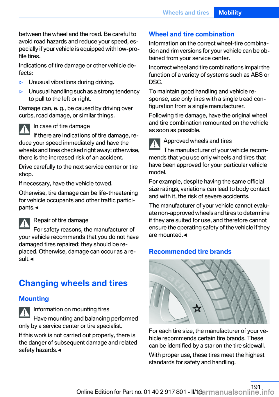
Recommended tire brands
For each tire size, the manufacturer of your ve‐
hicle recommends certain tire brands. These
can be identified by a star on the tire sidewall.
With proper use, these tires meet the highest
standards for safety and handling.
Seite 191Wheels and tiresMobility191
Online Edition for Part no. 01 40 2 917 801 - II/13
Page 199 of 242

CoolantVehicle equipment
All standard, country-specific and optional
equipment that is offered in the model series is
described in this chapter. Therefore, equipment
is also described that is not available in a vehicle,
e. g., because of the selected optional equip‐
ment or country variant. This also applies for
safety-related functions and systems.
General information Danger of burns from hot engine
Do not open the cooling system while the
engine is hot; otherwise, escaping coolant may
cause burns.◀
Suitable additives
Only use suitable additives; otherwise, en‐
gine damage may occur. The additives are
harmful to your health.◀
Coolant consists of water and additives.
Not all commercially available additives are suit‐
able for your vehicle. Ask your service center for
suitable additives.
Coolant level
Checking
Marks are provided on the side of the coolant
reservoir.SymbolMeaningMaximumMinimum1.Let the engine cool.2.The coolant level is correct when it is be‐
tween these two marks.Adding engine oil1.Let the engine cool.2.Turn the cap of the coolant reservoir slightly
counterclockwise to allow any excess pres‐
sure to dissipate, and then open it.3.If the coolant is low, slowly add coolant up to
the specified level; do not overfill.4.Turn the cap until there is an audible click.
The arrows on the coolant reservoir and the
cap must point towards one another.5.Have the cause of the coolant loss elimi‐
nated as soon as possible.
Disposal
Comply with the relevant environmental
protection regulations when disposing
of coolant and coolant additives.
Seite 199CoolantMobility199
Online Edition for Part no. 01 40 2 917 801 - II/13
Page 209 of 242
5.Remove the connecting line from the clip on
the bulb holder.6.Release the catch at the top on the connec‐
tor of the connecting line and remove the
connector from the bulb holder.
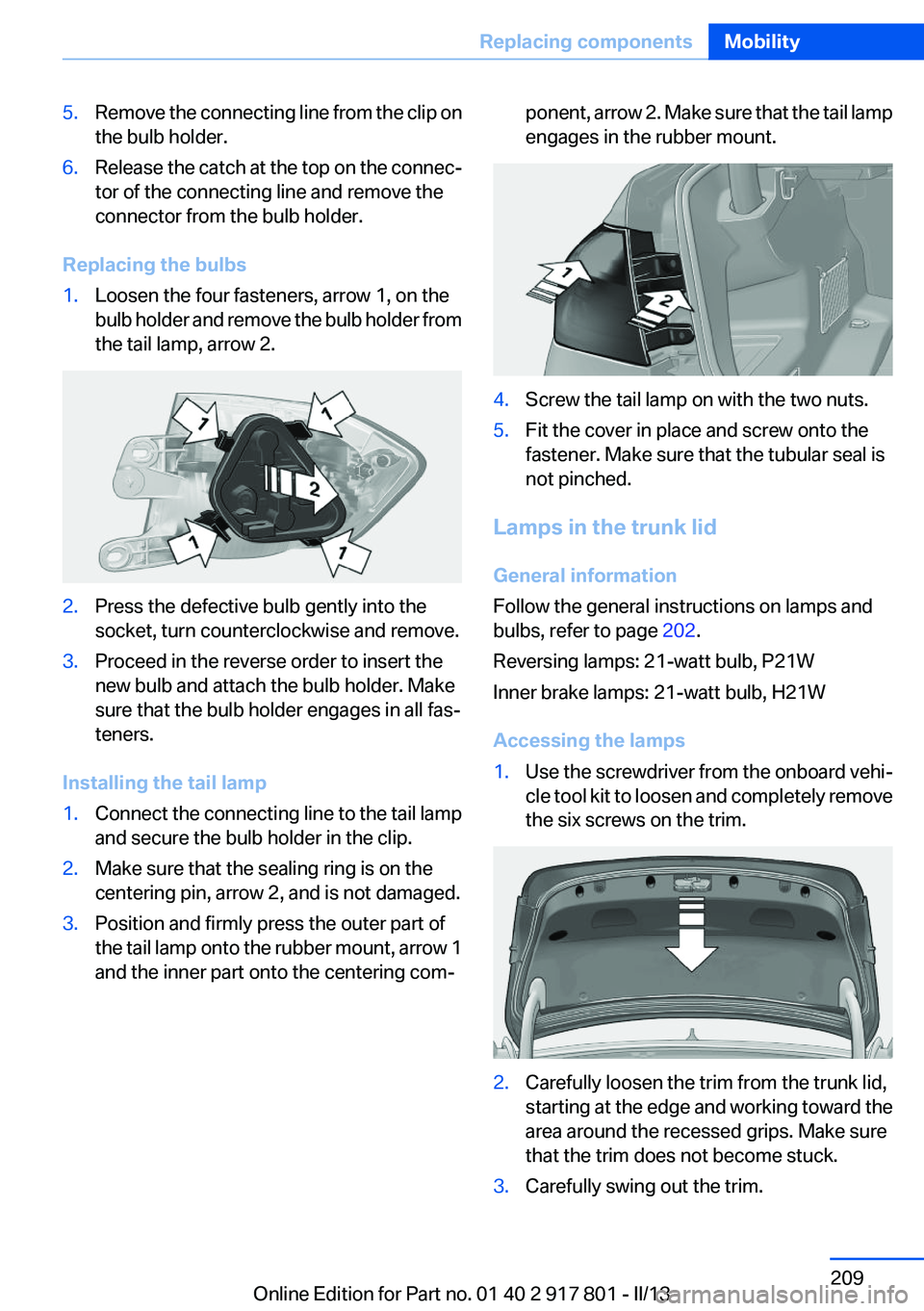
Replacing the bulbs
1.Loosen the four fasteners, arrow 1, on the
bulb holder and remove the bulb holder from
the tail lamp, arrow 2.2.Press the defective bulb gently into the
socket, turn counterclockwise and remove.3.Proceed in the reverse order to insert the
new bulb and attach the bulb holder. Make
sure that the bulb holder engages in all fas‐
teners.
Installing the tail lamp
1.Connect the connecting line to the tail lamp
and secure the bulb holder in the clip.2.Make sure that the sealing ring is on the
centering pin, arrow 2, and is not damaged.3.Position and firmly press the outer part of
the tail lamp onto the rubber mount, arrow 1
and the inner part onto the centering com‐ponent, arrow 2. Make sure that the tail lamp
engages in the rubber mount.4.Screw the tail lamp on with the two nuts.5.Fit the cover in place and screw onto the
fastener. Make sure that the tubular seal is
not pinched.
Lamps in the trunk lid
General information
Follow the general instructions on lamps and
bulbs, refer to page 202.
Reversing lamps: 21-watt bulb, P21W
Inner brake lamps: 21-watt bulb, H21W
Accessing the lamps
1.Use the screwdriver from the onboard vehi‐
cle tool kit to loosen and completely remove
the six screws on the trim.2.Carefully loosen the trim from the trunk lid,
starting at the edge and working toward the
area around the recessed grips. Make sure
that the trim does not become stuck.3.Carefully swing out the trim.Seite 209Replacing componentsMobility209
Online Edition for Part no. 01 40 2 917 801 - II/13