2013 BMW 335I remote control
[x] Cancel search: remote controlPage 51 of 242

Adjusting the height▷To raise: pull.▷To lower: press the button, arrow 1, and
push the head restraint down.
The center head restraint cannot be adjusted in
elevation.
Folding down head restraints Extending/retracting head restraint
Only fold down head restraint if no pas‐
sengers are in the rear. Fold out retracted headr‐
ests again if passengers are being carried in the
rear; otherwise, there is increased risk of injury
in the event of an accident.◀
▷To lower flaps: press the button, arrow 1,
and press down the head restraint.▷Fold back up: pull up head restraints.
Removing
Only remove the head restraint if no one will be
sitting in the seat in question.
1.Pull the head restraint upward as far as pos‐
sible.2.Press the button, arrow 1, and pull the head
restraint out completely.
Before transporting passengers
Reinstall the head restraint before trans‐
porting anyone in the seat; otherwise, the pro‐
tective function of the head restraint is unavail‐
able.◀
Seat and mirror memory
General information
Two different driver's seat and exterior mirror
positions can be stored and retrieved for each
remote control. Settings for the backrest width
and lumbar support are not stored in memory.
Storing
1.Switch on the ignition.2.Set the desired position.Seite 51AdjustingControls51
Online Edition for Part no. 01 40 2 917 801 - II/13
Page 52 of 242

3. Press the button. The LED in the
button lights up.4.Press the desired button 1 or 2. The LED
goes out.
If the M button is pressed accidentally:
Press the button again.
The LED goes out.
Calling up settings Do not retrieve the memory while driving
Do not retrieve the memory setting while
driving, as an unexpected movement of the seat
or steering wheel could result in an accident.◀
Comfort function
1.Open the driver's door.2.Switch off the ignition.3.Briefly press the desired button 1 or 2.
The corresponding seat position is performed
automatically.
The procedure stops when a switch for adjust‐
ing the seat or one of the buttons is pressed.
Safety mode
1.Close the driver's door or switch on the ig‐
nition.2.Press and hold the desired button 1 or 2 until
the adjustment procedure is completed.
Calling up of a seat position
deactivated
After a brief period, the calling up of stored seat
positions is deactivated to save battery power.
To reactivate calling up of a seat position:
▷Open and close the door or trunk lid.▷Press a button on the remote control.▷Press the Start/Stop button.Mirrors
Exterior mirrors
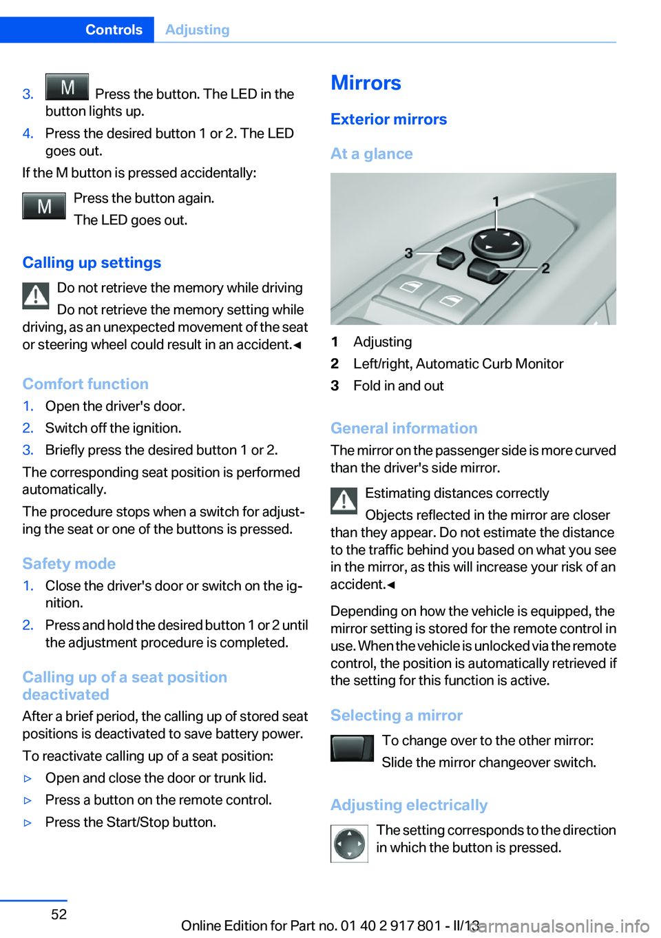
At a glance1Adjusting2Left/right, Automatic Curb Monitor3Fold in and out
General information
The mirror on the passenger side is more curved
than the driver's side mirror.
Estimating distances correctly
Objects reflected in the mirror are closer
than they appear. Do not estimate the distance
to the traffic behind you based on what you see
in the mirror, as this will increase your risk of an
accident.◀
Depending on how the vehicle is equipped, the
mirror setting is stored for the remote control in
use. When the vehicle is unlocked via the remote
control, the position is automatically retrieved if
the setting for this function is active.
Selecting a mirror To change over to the other mirror:
Slide the mirror changeover switch.
Adjusting electrically The setting corresponds to the direction
in which the button is pressed.
Seite 52ControlsAdjusting52
Online Edition for Part no. 01 40 2 917 801 - II/13
Page 61 of 242

Engine stop
General information Take the remote control with you
Take the remote control with you when
leaving the vehicle so that children, for example,
cannot start the engine.◀
Set the parking brake and further secure
the vehicle as required
Set the parking brake firmly when parking; oth‐
erwise, the vehicle could roll. On steep upward
and downward inclines, further secure the vehi‐
cle, for example, by turning the steering wheel in
the direction of the curb. ◀
Before driving into a car wash
In order for the vehicle to be able to roll into a car
wash, heed the information regarding Washing
in automatic car washes, refer to page 219.
Manual transmission
Switching off the engine1.With the vehicle at a standstill, press the
Start/Stop button.2.Shift into first gear or reverse.3.Set the parking brake.
Automatic transmission
Switching off the engine
1.Engage transmission position P with the ve‐
hicle stopped.2.Press the Start/Stop button.
The engine is switched off.
The radio ready state is switched on.3.Set the parking brake.Auto Start/Stop function
The concept
The Auto Start/Stop function helps save fuel.
The system switches off the engine during a
stop, e.g., in a traffic congestion or at traffic
lights. The ignition remains switched on. The
engine starts again automatically for driving off.
Certain vehicle components may experience
additional wear as a result of this system.
Automatic mode
The Auto Start/Stop function is operational after
each engine start.
This function is activated at speeds faster than
about 3 mph, approx. 5 km/h.
Engine stop
The engine is switched off automatically during
a stop under the following conditions:
Manual transmission:▷Neutral is engaged and the clutch pedal is
not pressed.▷The driver's safety belt is buckled or the
driver's door is closed.
Automatic transmission:
▷The selector lever is in transmission position
D.▷Brake pedal remains depressed while the
vehicle is stopped.▷The driver's safety belt is buckled or the
driver's door is closed.
The air flow of the air conditioner is reduced
when the engine is switched off.
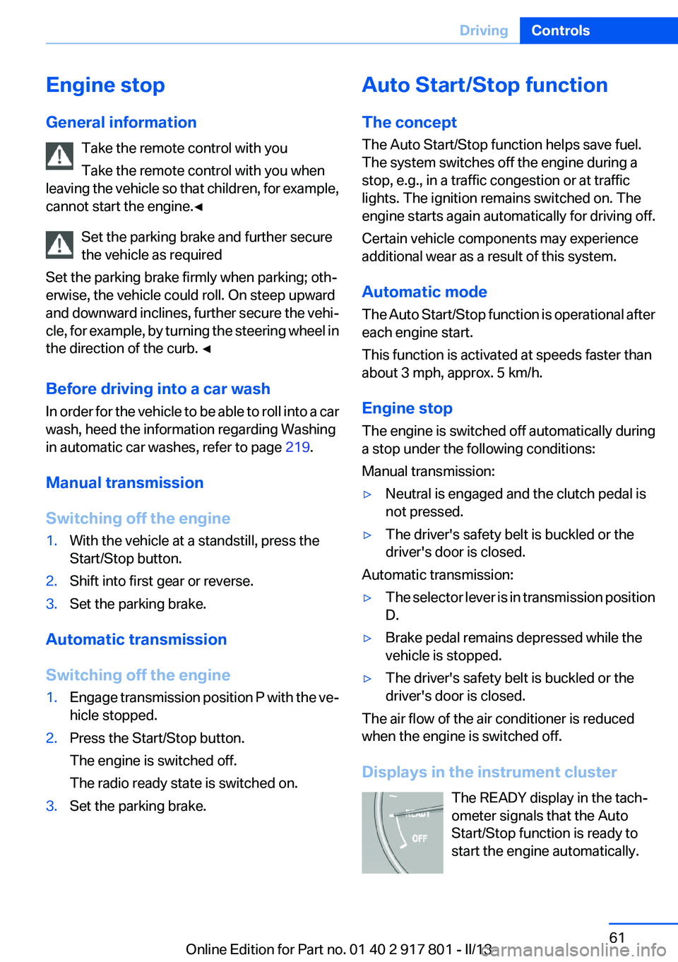
Displays in the instrument cluster The READY display in the tach‐
ometer signals that the Auto
Start/Stop function is ready to
start the engine automatically.
Seite 61DrivingControls61
Online Edition for Part no. 01 40 2 917 801 - II/13
Page 77 of 242

DateThe date is displayed in the in‐
strument cluster.
Setting the date and date format,
refer to page 84.
Range After the reserve range is
reached:▷A Check Control message is
displayed briefly.▷The remaining range is
shown on the onboard com‐
puter.▷When a dynamic driving style is used, such
as when cornering quickly, operation of the
engine is not always ensured.
The Check Control message appears continu‐
ously below a range of approx. 30 miles/50 km.
Refuel promptly
Refuel no later than at a range of
30 miles/50 km, or operation of the engine is not
ensured and damage may occur.◀
Displaying the cruising range
1."Settings"2."Info display"3."Additional indicators"
The range is displayed in the instrument cluster.
Current fuel consumption
Instrument cluster Displays the current fuel con‐
sumption. You can check
whether you are currently driving
in an efficient and environmen‐
tally-friendly manner.
Instrument cluster with enhanced
features
Displays the current fuel con‐
sumption. You can check
whether you are currently driving
in an efficient and environmen‐
tally-friendly manner.
Displaying the current fuel
consumption1."Settings"2."Info display"3."Additional indicators"
The bar display for the current fuel consumption
is displayed in the instrument cluster.
Energy recovery The kinetic energy of the vehicle
is converted to electrical energy
while coasting. The vehicle bat‐
tery is partially charged and fuel
consumption can be reduced.
Service requirements
The concept
The driving distance or the time to the next
scheduled maintenance is displayed briefly after
the ignition is switched on.
The current service requirements can be read
out from the remote control by the service spe‐
cialist.
Display
Data regarding the service status or legally man‐
dated inspections of the vehicle are automati‐
cally transmitted to your service center before a
service due date.
Seite 77DisplaysControls77
Online Edition for Part no. 01 40 2 917 801 - II/13
Page 85 of 242

Language
Setting the language
To set the language on the Control Display:1."Settings"2."Language/Units"3."Language:"4.Select the desired language.
The setting is stored for the remote control cur‐
rently in use.
Units of measure
Setting the units of measure
To set the units for fuel consumption, route/dis‐
tance and temperature:
1."Settings"2."Language/Units"3.Select the desired menu item.4.Select the desired unit.
The setting is stored for the remote control cur‐
rently in use.
Brightness
Setting the brightness
To set the brightness of the Control Display:1."Settings"2."Control display"3."Brightness"4.Turn the controller until the desired bright‐
ness is set.5.Press the controller.
The setting is stored for the remote control cur‐
rently in use.
Depending on the light conditions, the bright‐
ness control may not be clearly visible.
Assist system information
Display on the Control Display
Information on the Assist system can be dis‐
played by activating Assist on the Control Dis‐
play.
1."Settings"2."Control display"Seite 85DisplaysControls85
Online Edition for Part no. 01 40 2 917 801 - II/13
Page 87 of 242

LampsVehicle equipment
All standard, country-specific and optional
equipment that is offered in the model series is
described in this chapter. Therefore, equipment
is also described that is not available in a vehicle,
e. g., because of the selected optional equip‐
ment or country variant. This also applies for
safety-related functions and systems.
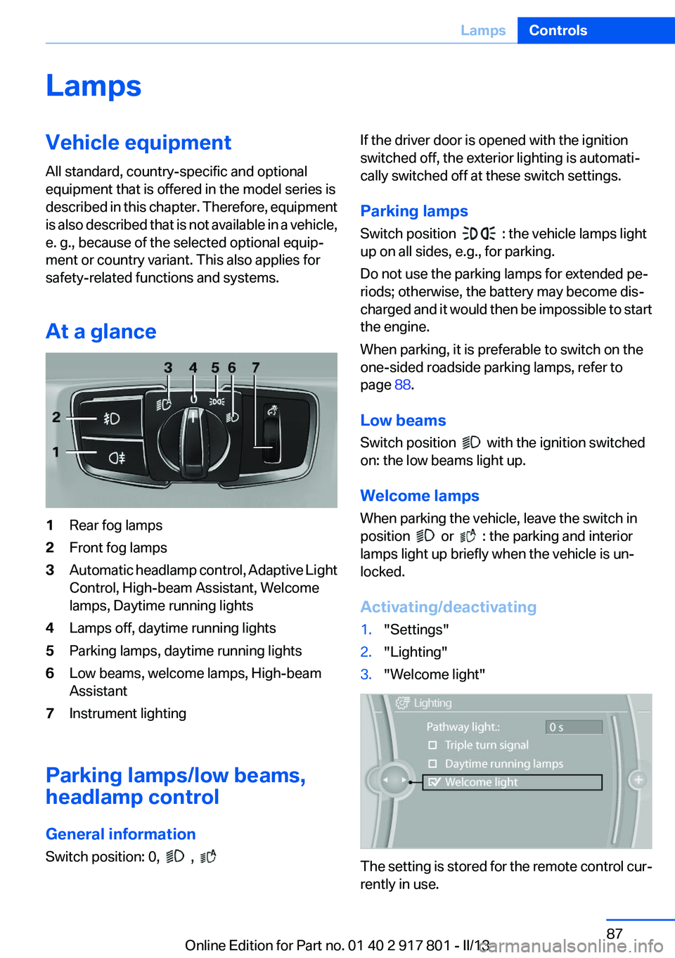
At a glance1Rear fog lamps2Front fog lamps3Automatic headlamp control, Adaptive Light
Control, High-beam Assistant, Welcome
lamps, Daytime running lights4Lamps off, daytime running lights5Parking lamps, daytime running lights6Low beams, welcome lamps, High-beam
Assistant7Instrument lighting
Parking lamps/low beams,
headlamp control
General information
Switch position: 0,
,
If the driver door is opened with the ignition
switched off, the exterior lighting is automati‐
cally switched off at these switch settings.
Parking lamps
Switch position
: the vehicle lamps light
up on all sides, e.g., for parking.
Do not use the parking lamps for extended pe‐
riods; otherwise, the battery may become dis‐
charged and it would then be impossible to start
the engine.
When parking, it is preferable to switch on the
one-sided roadside parking lamps, refer to
page 88.
Low beams
Switch position
with the ignition switched
on: the low beams light up.
Welcome lamps
When parking the vehicle, leave the switch in
position
or : the parking and interior
lamps light up briefly when the vehicle is un‐
locked.
Activating/deactivating
1."Settings"2."Lighting"3."Welcome light"
The setting is stored for the remote control cur‐
rently in use.
Seite 87LampsControls87
Online Edition for Part no. 01 40 2 917 801 - II/13
Page 88 of 242

Headlamp courtesy delay feature
The low beams stay lit for a short while if the
headlamp flasher is switched on after the igni‐
tion is switched off.
Setting the duration1."Settings"2."Lighting"3."Pathway light.: s"4.Set the duration.
The setting is stored for the remote control cur‐
rently in use.
Automatic headlamp control
Switch position
: the low beams are switched
on and off automatically, e.g., in tunnels, in twi‐
light or if there is precipitation. The indicator
lamp in the instrument cluster lights up.
A blue sky with the sun low on the horizon can
cause the lights to be switched on.
The low beams always stay on when the fog
lamps are switched on.
Personal responsibility
The automatic headlamp control cannot
serve as a substitute for your personal judgment
in determining when the lamps should be
switched on in response to ambient lighting
conditions.
For example, the sensors are unable to detect
fog or hazy weather. To avoid safety risks, you
should always switch on the lamps manually un‐
der these conditions.◀
Daytime running lights
With the ignition switched on, the daytime run‐
ning lights light up in position 0,
or .
After the ignition is switched off, the parking
lamps light up in position
.
Activating/deactivating
In some countries, daytime running lights are
compulsory, so it may not be possible to deac‐
tivate the daytime running lights.
1."Settings"2."Lighting"3."Daytime running lamps"
The setting is stored for the remote control cur‐
rently in use.
Roadside parking lamps
The vehicle can be illuminated on one side.
Switching on
With the ignition switched off, press the lever
either up or down past the resistance point for
approx. 2 seconds.
Seite 88ControlsLamps88
Online Edition for Part no. 01 40 2 917 801 - II/13
Page 101 of 242

Switching on/off
Switching the warning function on/off
Press the button
▷On: the LED lights up.▷Off: the LED goes out.
The state is stored for the remote control cur‐
rently in use.
Setting the warning time
The warning time can be set via iDrive, refer to
page 85.
1.Activate collision warning.2.Activate the desired warning time on the
Control Display.
The selected channel is stored for the remote
control currently in use.
Display
Warning stages
Prewarning
This warning is issued, for example, when there
is the impending danger of a collision or the dis‐
tance to the vehicle ahead is too small.
Acute warning with braking function
Warning of the imminent danger of a collision
when the vehicle approaches another object at
a relatively high differential speed.
The acute warning prompts the driver to inter‐
vene and, if there is the danger of a collision, is
accompanied by a braking intervention.
The braking intervention is executed with lim‐
ited braking force and for a brief period only. The
intervention will not bring the vehicle to a com‐
plete standstill.
The braking intervention is executed only if DSC
Dynamic Stability Control is switched on.
Adapting your speed and driving style
The acute warning does not relieve the
driver of the responsibility to adapt his or her
driving speed and style to the traffic condi‐
tions.◀
The braking intervention can be interrupted by
pressing on the accelerator or by actively mov‐
ing the steering wheel.
When towing or tow-starting the vehicle, switch
off the collision warning with braking function to
prevent undesired interventions.
The braking function is deactivated if the DSC
Dynamic Stability Control or DTC Dynamic
Traction Control is deactivated.
Display in the instrument cluster
The collision warning can be issued in the in‐
strument cluster, in the Head-up Display, and
acoustically.
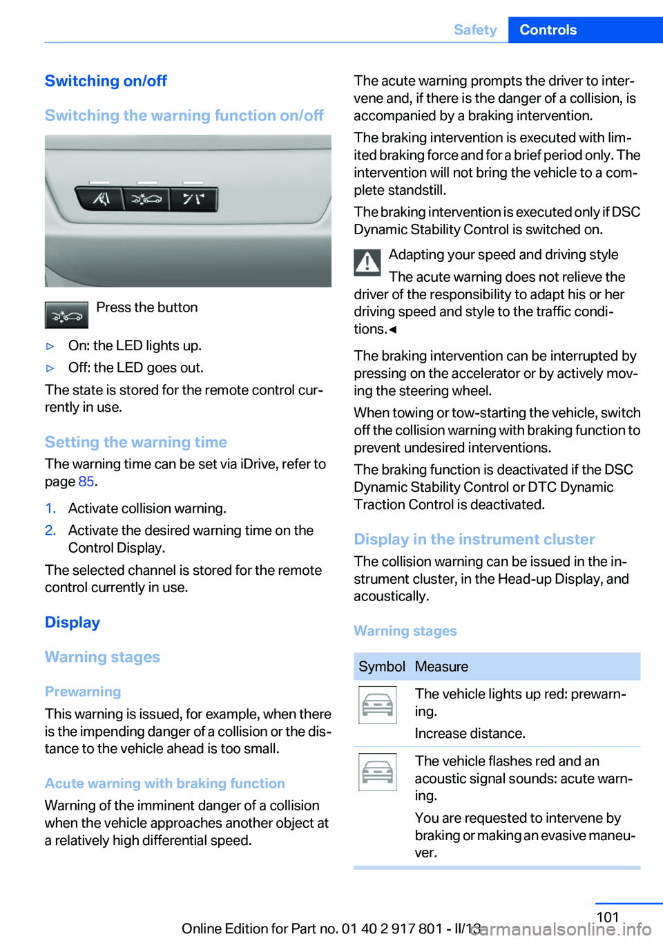
Warning stagesSymbolMeasureThe vehicle lights up red: prewarn‐
ing.
Increase distance.The vehicle flashes red and an
acoustic signal sounds: acute warn‐
ing.
You are requested to intervene by
braking or making an evasive maneu‐
ver.Seite 101SafetyControls101
Online Edition for Part no. 01 40 2 917 801 - II/13