2013 BMW 335I check engine
[x] Cancel search: check enginePage 99 of 242

2."Vehicle status"3. "Flat Tire Monitor"
The status is displayed.
Initialization
The initialization process adopts the set inflation
tire pressures as reference values for the detec‐
tion of a flat tire. Initialization is started by con‐
firming the inflation pressures.
Do not initialize the system when driving with
snow chains.
1."Vehicle Info"2."Vehicle status"3. "Reset"4.Start the engine - do not drive away.5.Start the initialization with "Reset".6.Drive away.
The initialization is completed while driving,
which can be interrupted at any time.
The initialization automatically continues when
driving resumes.
Indication of a flat tire The yellow warning lamp lights up. A
Check Control message is displayed.
There is a flat tire or a major loss in tire
inflation pressure.
1.Reduce your speed and stop cautiously.
Avoid sudden braking and steering maneu‐
vers.2.Check whether the vehicle is fitted with reg‐
ular tires or run-flat tires.
Run-flat tires, refer to page 192, are labeled
with a circular symbol containing the letters
RSC marked on the tire sidewall.
Do not continue driving without run-flat
tires
Do not continue driving if the vehicle is not
equipped with run-flat tires; continued driving
may result in serious accidents.◀
When a flat tire is indicated, DSC Dynamic Sta‐
bility Control is switched on if necessary.
System limits Sudden tire damage
Sudden serious tire damage caused by
external influences cannot be indicated in ad‐
vance.◀
A natural, even pressure loss in all four tires can‐
not be detected. Therefore, check the tire infla‐
tion pressure regularly.
The system could be delayed or malfunction in
the following situations:▷When the system has not been initialized.▷When driving on a snowy or slippery road
surface.▷Sporty driving style: slip in the drive wheels,
high lateral acceleration.▷When driving with snow chains.
Actions in the event of a flat tire
Normal tires
1.Identify the damaged tire.
Do this by checking the air pressure in all
four tires.
If the tire inflation pressure in all four tires is
correct, the Flat Tire Monitor may not have
been initialized. In this case, initialize the
system.
If an identification is not possible, please
contact the service center.2.Rectify the flat tire.
Run-flat tires
Maximum speed
You can continue driving with a damaged tire at
speeds up to 50 mph/80 km/h.
Seite 99SafetyControls99
Online Edition for Part no. 01 40 2 917 801 - II/13
Page 107 of 242
A Check Control message is displayed when the
system is not fully functional.
For US owners only
The transmitter and receiver units comply with
part 15 of the FCC/Federal Communication
Commission regulations. Operation is governed
by the following:
FCC ID:▷NBG009014A.
Compliance statement:
This device complies with part 15 of the FCC
Rules. Operation is subject to the following two
conditions:
▷This device may not cause harmful interfer‐
ence, and▷this device must accept any interference re‐
ceived, including interference that may
cause undesired operation.
Any unauthorized modifications or changes to
these devices could void the user's authority to
operate this equipment.
Brake force display
The concept
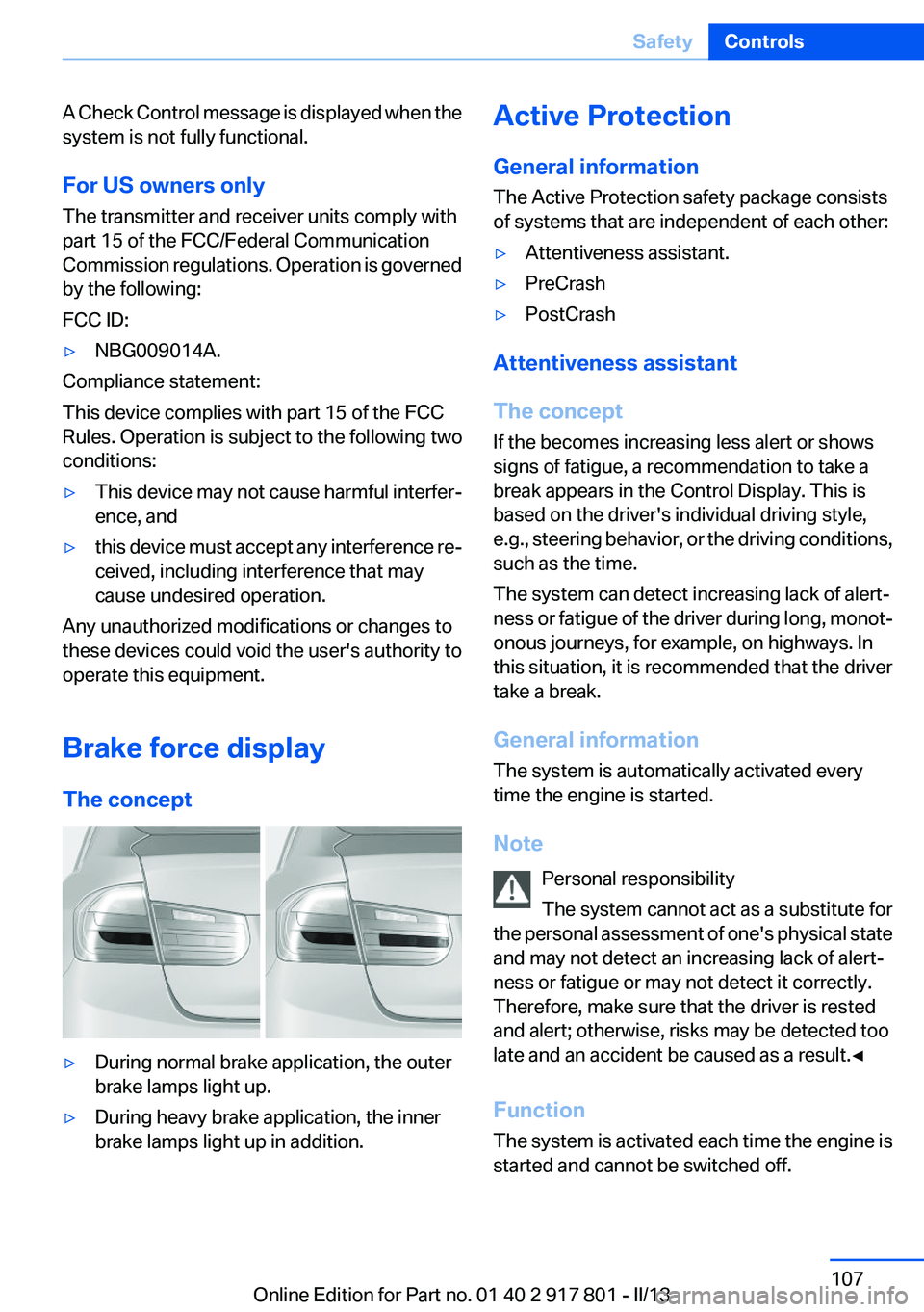
▷During normal brake application, the outer
brake lamps light up.▷During heavy brake application, the inner
brake lamps light up in addition.Active Protection
General information
The Active Protection safety package consists
of systems that are independent of each other:▷Attentiveness assistant.▷PreCrash▷PostCrash
Attentiveness assistant
The concept
If the becomes increasing less alert or shows
signs of fatigue, a recommendation to take a
break appears in the Control Display. This is
based on the driver's individual driving style,
e.g., steering behavior, or the driving conditions,
such as the time.
The system can detect increasing lack of alert‐
ness or fatigue of the driver during long, monot‐
onous journeys, for example, on highways. In
this situation, it is recommended that the driver
take a break.
General information
The system is automatically activated every
time the engine is started.
Note Personal responsibility
The system cannot act as a substitute for
the personal assessment of one's physical state
and may not detect an increasing lack of alert‐
ness or fatigue or may not detect it correctly.
Therefore, make sure that the driver is rested
and alert; otherwise, risks may be detected too
late and an accident be caused as a result.◀
Function
The system is activated each time the engine is
started and cannot be switched off.
Seite 107SafetyControls107
Online Edition for Part no. 01 40 2 917 801 - II/13
Page 118 of 242
While standingBefore leaving the vehicle, secure it
against rolling.
Before leaving the vehicle with the engine run‐
ning, engage position P of the automatic trans‐
mission and apply the parking brake. Otherwise,
the vehicle may begin to roll.◀
The system brought the vehicle to a complete
standstill:▷Green marking in the speedometer:
Your vehicle accelerates automatically as
soon as the vehicle in the range of the radar
sensor moves off.▷Marking in the speedometer turns orange:
no automatic driving away.
To accelerate to the desired speed auto‐
matically, press the accelerator briefly or
press the RES or SET button.
Rolling bars in the distance display indicate that
the vehicle in the radar sensor detection range
has moved off.
Your vehicle was braked to a halt by pressing on
the brake pedal and it is standing behind another
vehicle:
1. Press the button to call up a stored
desired speed.2.Release the brake pedal.3.Press on the accelerator briefly, or press the
RES button or the rocker switch when the
vehicle ahead of you drives away.
Displays in the instrument cluster
Desired speed
▷The marking lights up green:
the system is active.▷The marking lights up or‐
ange: the system has been
interrupted.▷The marking does not light up: the system is
switched off.
Brief status display
Selected desired speed.
If --- appears briefly on the display for Check
Control messages, it is possible that the system
requirements for operation are currently not
met.
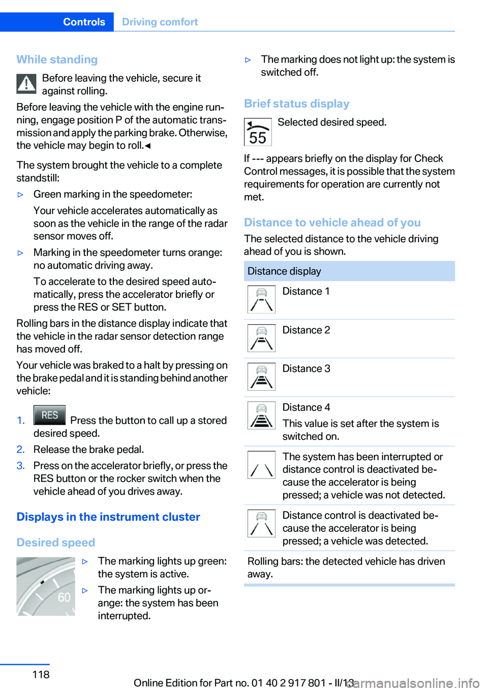
Distance to vehicle ahead of you
The selected distance to the vehicle driving
ahead of you is shown.
Distance displayDistance 1Distance 2Distance 3Distance 4
This value is set after the system is
switched on.The system has been interrupted or
distance control is deactivated be‐
cause the accelerator is being
pressed; a vehicle was not detected.Distance control is deactivated be‐
cause the accelerator is being
pressed; a vehicle was detected.Rolling bars: the detected vehicle has driven
away.Seite 118ControlsDriving comfort118
Online Edition for Part no. 01 40 2 917 801 - II/13
Page 126 of 242
NotesCheck the traffic situation as well
Check the traffic situation around the ve‐
hicle with your own eyes. Otherwise, an accident
could result from road users or objects located
outside the picture area of the backup camera. ◀
At a glance
Button in the vehicle
Backup camera
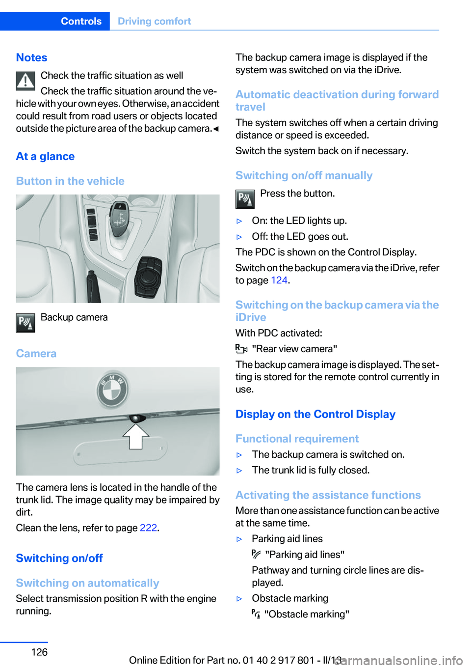
Camera
The camera lens is located in the handle of the
trunk lid. The image quality may be impaired by
dirt.
Clean the lens, refer to page 222.
Switching on/off
Switching on automatically
Select transmission position R with the engine
running.
The backup camera image is displayed if the
system was switched on via the iDrive.
Automatic deactivation during forward
travel
The system switches off when a certain driving
distance or speed is exceeded.
Switch the system back on if necessary.
Switching on/off manually Press the button.▷On: the LED lights up.▷Off: the LED goes out.
The PDC is shown on the Control Display.
Switch on the backup camera via the iDrive, refer
to page 124.
Switching on the backup camera via the
iDrive
With PDC activated:
"Rear view camera"
The backup camera image is displayed. The set‐
ting is stored for the remote control currently in
use.
Display on the Control Display
Functional requirement
▷The backup camera is switched on.▷The trunk lid is fully closed.
Activating the assistance functions
More than one assistance function can be active
at the same time.
▷Parking aid lines
"Parking aid lines"
Pathway and turning circle lines are dis‐
played.
▷Obstacle marking
"Obstacle marking"
Seite 126ControlsDriving comfort126
Online Edition for Part no. 01 40 2 917 801 - II/13
Page 128 of 242
Display settings
Brightness
With the backup camera switched on:1. Select the symbol.2.Turn the controller until the desired setting
is reached and press the controller.
Contrast
With the backup camera switched on:
1. Select the symbol.2.Turn the controller until the desired setting
is reached and press the controller.
System limits
Detection of objects
High, protruding objects such as ledges may not
be detected by the backup camera.
Top View
The concept
Top View assists you in parking and maneuver‐
ing. The area around the doors and the road area
around the vehicle are shown on the Control
Display for this purpose.
General information
The image is captured by two cameras
integrated in the exterior mirrors and by the
backup camera.
The range is at least 7 ft/2 m to the side and rear.
In this way, obstacles up to the height of the ex‐
terior mirrors are detected early.
Notes
Check the traffic situation as well
Check the traffic situation around the ve‐
hicle with your own eyes. Otherwise, an accident
could result from road users or objects located
outside the picture area of the cameras.◀
At a glance
Button in the vehicle
Top View
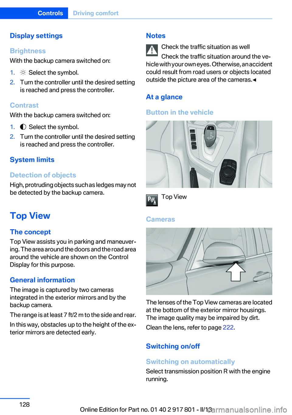
Cameras
The lenses of the Top View cameras are located
at the bottom of the exterior mirror housings.
The image quality may be impaired by dirt.
Clean the lens, refer to page 222.
Switching on/off
Switching on automatically
Select transmission position R with the engine
running.
Seite 128ControlsDriving comfort128
Online Edition for Part no. 01 40 2 917 801 - II/13
Page 164 of 242
Saving fuelVehicle equipment
All standard, country-specific and optional
equipment that is offered in the model series is
described in this chapter. Therefore, equipment
is also described that is not available in a vehicle,
e. g., because of the selected optional equip‐
ment or country variant. This also applies for
safety-related functions and systems.
General information
Your vehicle contains advanced technology for
the reduction of fuel consumption and emis‐
sions.
Fuel consumption depends on a number of dif‐
ferent factors.
The implementation of certain measures, driv‐
ing style and regular maintenance can have an
influence on fuel consumption and on the envi‐
ronmental impact.
Remove unnecessary cargo
Additional weight increases fuel consumption.
Remove attached parts
following use
Remove auxiliary mirrors, roof or rear luggage
racks which are no longer required following
use.
Attached parts on the vehicle impair the aero‐
dynamics and increase the fuel consumption.Close the windows and glass
sunroof
Driving with the glass sunroof and windows
open results in increased air resistance and
raises fuel consumption.
Tires
General information
Tires can affect consumption values in various
ways, for instance consumption can be influ‐
enced by the size of the tires.
Check the tire inflation pressure
regularly
Check and, if necessary, correct the tire inflation
pressure at least twice a month and before start‐
ing on a long trip.
Low tire inflation pressure increases rolling re‐
sistance and thus raises fuel consumption and
tire wear.
Drive away without delay
Do not wait for the engine to warm up while the
vehicle remains stationary. Start driving right
away, but at moderate engine speeds.
This is the fastest way for the cold engine to
reach its operating temperature.
Look well ahead when driving
Avoid unnecessary acceleration and braking.
By maintaining a suitable distance to the vehicle
driving ahead of you.
Driving smoothly and looking ahead reduces
fuel consumption.Seite 164Driving tipsSaving fuel164
Online Edition for Part no. 01 40 2 917 801 - II/13
Page 175 of 242

Use only Ultra-Low Sulfur Diesel.
The fraction of biodiesel in the fuel must
not exceed 5 %, referred to as B5. Do not use
gasoline. If you do fill the tank with the wrong
fuel, e.g., gasoline, do not start the engine as this
may damage the engine.◀
After adding the wrong fuel, contact your service
center or roadside assistance.
If the fuel pump nozzle does not fit in the filler
pipe of your BMW, please check to ensure that
you are refueling at a diesel fuel pump that is
equipped with a diesel fuel pump nozzle.
In the event the Ultra-Low Sulfur Diesel fuel can‐
not be fully inserted into the fuel filler neck,
please contact BMW Roadside Assistance for
instructions on how to add fuel. For more infor‐
mation on BMW Roadside Assistance, refer to
page 214.
Winter diesel
To ensure that the diesel engine remains op‐
erational in the winter, use winter diesel.
It is available at gas stations during winter
months.
The fuel filter heating system, included as a
standard feature, prevents disruption of the fuel
supply while driving.
Do not add any diesel additives
Do not add additives, including gasoline;
otherwise, engine damage may occur.◀For vehicles equipped with
BMW Advanced Diesel
The concept
BMW Advanced Diesel reduces nitrogen oxides
in the diesel emissions from your vehicle by in‐
jecting Diesel exhaust fluid reducing agent into
the exhaust system. A chemical reaction takes
place inside the catalytic converter that mini‐
mizes nitrogen oxides.
In order to be able to start the engine as usual,
there must be sufficient Diesel exhaust fluid
present in the separate container.
Warming up the system
In order to warm the engine up to its operating
temperature after a cold start, the automatic
transmission may subsequently shift up to the
next higher gear.
Displays in the instrument cluster
Reserve display
This display in the instrument cluster provides
information about the distance that can still be
driven with the current reserve level.
The Reserve display appears af‐
ter about 1,000 miles/1,600 km
before the supply is predicted to
run out.
Refill in good time
The Diesel exhaust fluid must be replen‐
ished as soon as the Reserve display appears,
otherwise the engine cannot be restarted.◀
Diesel exhaust fluid on minimum The engine will continue to run
even when the display shows --
mls, as long as it is not switched
off and all other operating condi‐
tions are satisfied, sufficient fuel
for example.Seite 175FuelMobility175
Online Edition for Part no. 01 40 2 917 801 - II/13
Page 195 of 242

Hood
Hints Working in the engine compartment
Never attempt to perform any service or
repair operations on your vehicle without the
necessary professional technical training.
If you are unfamiliar with the statutory guide‐
lines, have any work on the vehicle performed
only by a service center.
If this work is not carried out properly, there is
the danger of subsequent damage and related
safety hazards.◀
Never reach into the engine compartment
Never reach into the intermediate spaces
or gaps in the engine compartment. Otherwise,
there is risk of injury, e.g. from rotating or hot
parts.◀
Fold down wiper arm
Before opening the hood, ensure that the
wiper arms are against the windshield, or this
may result in damage.◀
Opening the hood1.Pull lever in the interior:
Engine is released, arrow 1.2.After the lever is released, pull the lever
again:
Hood can be opened, arrow 2.Indicator/warning lamps
When the hood is opened, a Check Control mes‐
sage is displayed.
Closing the hood
Let the hood drop from a height of approx.
16 in/40 cm and push down on it to lock it fully.
The hood must audibly engage on both sides.
Hood open when driving
If you see any signs that the hood is not
completely closed while driving, pull over imme‐
diately and close it securely.◀
Danger of pinching
Make sure that the closing path of the
hood is clear; otherwise, injuries may result.◀
Seite 195Engine compartmentMobility195
Online Edition for Part no. 01 40 2 917 801 - II/13