2013 BMW 3 SERIES SEDAN lock
[x] Cancel search: lockPage 203 of 248

Hood
Hints Working in the engine compartment
Never attempt to perform any service or
repair operations on your vehicle without the
necessary professional technical training.
If you are unfamiliar with the statutory guide‐
lines, have any work on the vehicle performed
only by a service center.
If this work is not carried out properly, there is
the danger of subsequent damage and related
safety hazards.◀
Never reach into the engine compart‐
ment
Never reach into the intermediate spaces or
gaps in the engine compartment. Otherwise,
there is risk of injury, e.g., from rotating or hot
parts.◀
Fold down wiper arm
Before opening the hood, ensure that the
wiper arms are against the windshield, or this
may result in damage.◀
Opening the hood1.Pull lever in the interior:
Engine is released, arrow 1.2.After the lever is released, pull the lever
again:
Hood can be opened, arrow 2.Indicator/warning lamps
When the hood is opened, a Check Control
message is displayed.
Closing the hood
Let the hood drop from a height of approx. 16
in/40 cm and push down on it to lock it fully.
The hood must audibly engage on both sides.
Hood open when driving
If you see any signs that the hood is not
completely closed while driving, pull over im‐
mediately and close it securely.◀
Danger of pinching
Make sure that the closing path of the
hood is clear; otherwise, injuries may result.◀
Seite 199Engine compartmentMobility199
Online Edition for Part no. 01 40 2 926 810 - X/13
Page 207 of 248

CoolantVehicle equipmentAll standard, country-specific and optional
equipment that is offered in the model series is
described in this chapter. Therefore, equip‐
ment is also described that is not available in a
vehicle, e. g., because of the selected optional
equipment or country variant. This also applies
for safety-related functions and systems.
Hints Danger of burns from hot engine
Do not open the cooling system while
the engine is hot; otherwise, escaping coolant
may cause burns.◀
Suitable additives
Only use suitable additives; otherwise,
engine damage may occur. The additives are
harmful to your health.◀
Coolant consists of water and additives.
Not all commercially available additives are
suitable for the vehicle. Information about the
suitable additives are available from the service
center.
Coolant level
Checking1.Let the engine cool.2.The coolant level is correct if it lies be‐
tween the minimum and maximum marks.
The marks are on the side of the coolant
reservoir.SymbolMeaningMaximumMinimum
Filling
1.Let the engine cool.2.Turn the cap of the coolant reservoir
slightly counterclockwise to allow any ex‐
cess pressure to dissipate, and then open
it.3.If the coolant is low, slowly add coolant up
to the specified level; do not overfill.4.Turn the cap until there is an audible click.
The arrows on the coolant reservoir and
the cap must point towards one another.5.Have the cause of the coolant loss elimi‐
nated as soon as possible.
Disposal
Comply with the relevant environmen‐
tal protection regulations when dispos‐
ing of coolant and coolant additives.
Seite 203CoolantMobility203
Online Edition for Part no. 01 40 2 926 810 - X/13
Page 210 of 248

Replacing componentsVehicle equipmentAll standard, country-specific and optional
equipment that is offered in the model series is
described in this chapter. Therefore, equip‐
ment is also described that is not available in a
vehicle, e. g., because of the selected optional
equipment or country variant. This also applies
for safety-related functions and systems.
Onboard vehicle tool kit
The onboard vehicle tool kit is located on the
right side in the cargo area in a storage com‐
partment. Open the cover.
Wiper blade replacement Note Do not fold down the wipers without
wiper blades
Do not fold down the wipers if wiper blades
have not been installed; this may damage the
windshield.◀
Replacing the wiper blades
1.To change the wiper blades, fold up, refer
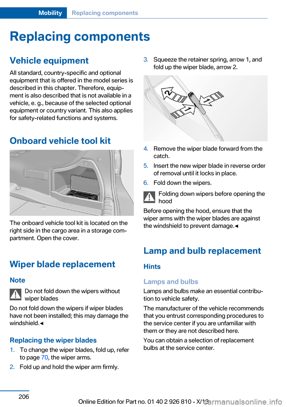
to page 70, the wiper arms.2.Fold up and hold the wiper arm firmly.3.Squeeze the retainer spring, arrow 1, and
fold up the wiper blade, arrow 2.4.Remove the wiper blade forward from the
catch.5.Insert the new wiper blade in reverse order
of removal until it locks in place.6.Fold down the wipers.
Folding down wipers before opening the hood
Before opening the hood, ensure that the
wiper arms with the wiper blades are against
the windshield to prevent damage.◀
Lamp and bulb replacement
Hints
Lamps and bulbs Lamps and bulbs make an essential contribu‐
tion to vehicle safety.
The manufacturer of the vehicle recommends
that you entrust corresponding procedures to
the service center if you are unfamiliar with
them or they are not described here.
You can obtain a selection of replacement
bulbs at the service center.
Seite 206MobilityReplacing components206
Online Edition for Part no. 01 40 2 926 810 - X/13
Page 212 of 248

Accessing the turn signals and low beams
Follow the general instructions on Lamps and
bulbs, refer to page 206.1.In the wheel house, loosen the two brack‐
ets and remove the cover.
Turn signal
21-watt bulb, PY21W
1.If necessary, pull the inside trim of the
wheel house slightly inward. Turn the bulb
holder counterclockwise and remove.2.Press the bulb gently into the socket, turn
counterclockwise and remove.3.Install the new bulb and bulb holder in re‐
verse order of removal.4.Attach the cover to the wheel house.Low beams
55-watt bulb, H7.1.Turn the cap counterclockwise and re‐
move.2.Tilt the bulb down and then up to loosen it
from the holder and remove.3.Pull the connector off the bulb.4.Attach the connector to the new bulb.5.First insert the bulb at the top with the
strap, arrow 1, and then press down firmly,
arrow 2. Make sure that the bulb snaps into
place.6.Close the headlamp housing with the cap.
Make sure that the cap engages.7.Attach the cover to the wheel house.Seite 208MobilityReplacing components208
Online Edition for Part no. 01 40 2 926 810 - X/13
Page 213 of 248

Accessing the daytime running lights, high
beams/headlamp flasher and parking
lamps
Follow the general instructions on Lamps and
bulbs, refer to page 206.1.Open the hood, refer to page 199.2.Turn the cap counterclockwise and re‐
move.
Parking lamps
6-watt bulb, H6W.
1.Turn the bulb holder counterclockwise and
remove.2.Press the bulb gently into the socket, turn
counterclockwise and remove.3.To insert the bulb and bulb holder, proceed
in reverse order of removal. Make sure that
the bulb holder snaps into place.4.Close the headlamp housing with the cap.
Make sure that the cap engages.High beams/headlamp flasher
55-watt bulb, H7.1.Tilt the bulb down and then up to loosen it
from the holder and remove.2.Pull the connector off the bulb.3.Attach the connector to the new bulb.4.First insert the bulb at the top with the
strap, arrow 1, and then press down firmly,
arrow 2. Make sure that the bulb snaps into
place.5.Close the headlamp housing with the cap.
Make sure that the cap engages.Seite 209Replacing componentsMobility209
Online Edition for Part no. 01 40 2 926 810 - X/13
Page 215 of 248

21-watt bulb, PY21W1.In the wheel house, loosen the two brack‐
ets and remove the cover.2.If necessary, pull the inside trim of the
wheel house slightly inward. Turn the bulb
holder counterclockwise and remove.3.Press the bulb gently into the socket, turn
counterclockwise and remove.4.Install the new bulb and bulb holder in re‐
verse order of removal.5.Attach the cover to the wheel house.
Front fog lamps
Follow the general instructions on Lamps and
bulbs, refer to page 206.
35-watt bulb, H8.
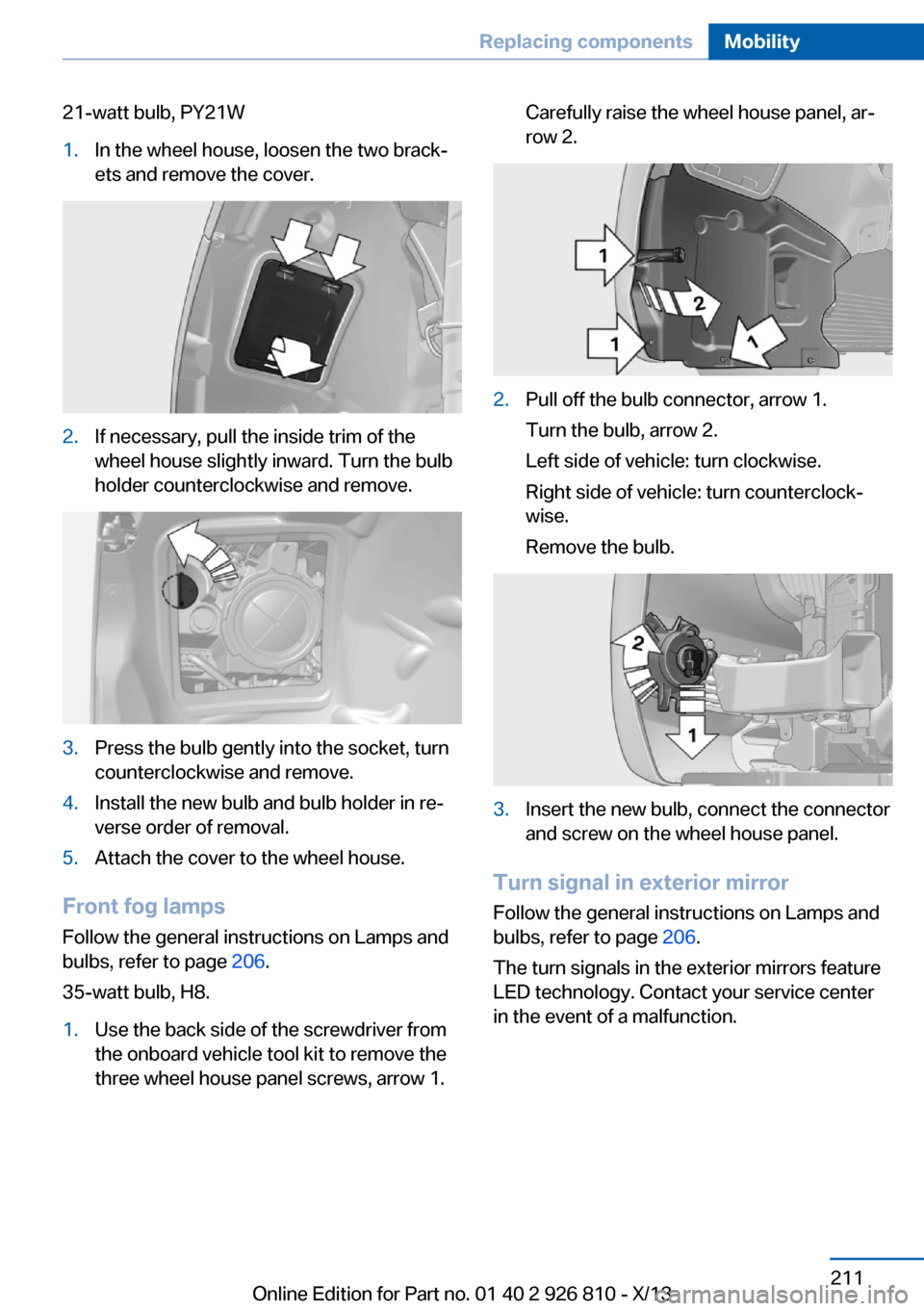
1.Use the back side of the screwdriver from
the onboard vehicle tool kit to remove the
three wheel house panel screws, arrow 1.Carefully raise the wheel house panel, ar‐
row 2.2.Pull off the bulb connector, arrow 1.
Turn the bulb, arrow 2.
Left side of vehicle: turn clockwise.
Right side of vehicle: turn counterclock‐
wise.
Remove the bulb.3.Insert the new bulb, connect the connector
and screw on the wheel house panel.
Turn signal in exterior mirror
Follow the general instructions on Lamps and
bulbs, refer to page 206.
The turn signals in the exterior mirrors feature
LED technology. Contact your service center
in the event of a malfunction.
Seite 211Replacing componentsMobility211
Online Edition for Part no. 01 40 2 926 810 - X/13
Page 217 of 248

5.Remove the connecting line from the clip
on the bulb holder.6.Release the catch at the top on the con‐
nector of the connecting line and remove
the connector from the bulb holder.
Replacing the bulbs
1.Loosen the four fasteners, arrow 1, on the
bulb holder and remove the bulb holder
from the tail lamp, arrow 2.2.Press the defective bulb gently into the
socket, turn counterclockwise and remove.3.Proceed in the reverse order to insert the
new bulb and attach the bulb holder. Make
sure that the bulb holder engages in all fas‐
teners.
Installing the tail lamp
1.Connect the connecting line to the tail
lamp and secure the bulb holder in the clip.2.Make sure that the foam rubber sealing
ring is on the centering pin, arrow 2, and is
not damaged.3.Position and firmly press the outer part of
the tail lamp onto the rubber mount, ar‐
row 1 and the inner part onto the centeringcomponent, arrow 2. Make sure that the
tail lamp engages in the rubber mount.4.Screw the tail lamp on with the two nuts.5.Fit the cover in place and screw onto the
fastener. Make sure that the tubular seal is
not pinched.
Lamps in the trunk lid
General information
Follow the general instructions on Lamps and
bulbs, refer to page 206.
Reversing lamps: 16-watt bulb, PW16W.
Inner brake lamps: 21-watt bulb, H21W
Accessing the lamps
1.Use the screwdriver from the onboard ve‐
hicle tool kit to loosen and completely re‐
move the six screws on the trim.2.Carefully loosen the trim from the trunk lid,
starting at the edge and working toward
the area around the recessed grips. Make
sure that the trim does not become stuck.3.Carefully swing out the trim.Seite 213Replacing componentsMobility213
Online Edition for Part no. 01 40 2 926 810 - X/13
Page 218 of 248

Replacing the reversing lamp and inner
brake lamp1.Loosen the two holders, arrow 1 and pull
down on the lamp holder to remove, ar‐
row 2.2.Unscrew the defective bulb from the
socket counterclockwise for reversing or
rear fog lamps.3.Insert the new bulb.
Installing the bulb holder
1.Slide the bulb holder onto the two guide
pins, arrow 1. Insert the two contacts, ar‐
row 2, into the connections, arrow 3.2.Press on the bulb holder. Make sure that
the two exterior holders latch into place.3.Swing the trim back onto the trunk lid and
secure.
Tail lamp, license plate lamp and
central brake lamp
Follow the general instructions on Lamps and
bulbs, refer to page 206.
These lamps are made using LED technology.
Contact your service center in the event of a
malfunction.
Changing wheels
Hints The vehicle equipment does not include a
spare tire.
When using run-flat tires or tire sealants, a tire
does not need to be changed immediately in
the event of pressure loss due to a flat tire.
The tools for changing wheels are available as
accessories from your service center.
Jacking points for the vehicle jack
The jacking points for the vehicle jack are lo‐
cated at the positions shown.
Vehicle battery Maintenance
The battery is maintenance-free. The added
amount of acid is sufficient for the service life
of the battery.
Your service center will be glad to advise you
on questions regarding the battery.
Seite 214MobilityReplacing components214
Online Edition for Part no. 01 40 2 926 810 - X/13