2013 BMW 3 SERIES SEDAN Limit
[x] Cancel search: LimitPage 140 of 248

At a glance
Button in the vehicle
Side View
Cameras
Two cameras integrated in the bumpers cap‐
ture the image.
The two camera lenses are located on the
sides of the bumper.
The image quality may be impaired by dirt.
Clean the lens, refer to page 226.
Switching on/off
Switching on/off manually Press the button.
Automatic deactivation during forward
travel
The system switches off when a certain driving
distance or speed is exceeded.
Switch the system back on if necessary.
Display
The traffic area to the left and right is displayed
on the Control Display.
Guidelines at the bottom of the image show
the position of the front of the vehicle.
Brightness With the Side View switched on:
1. "Brightness"2.Turn the controller until the desired setting
is reached, and press the controller.
Contrast
With the Side View switched on:
1. "Contrast"2.Turn the controller until the desired setting
is reached, and press the controller.
System limits
The cameras capture a maximum range of
330 ft/100 m.
Top View
The concept Top View provides assistance in parking and
maneuvering. The area around the doors and
the road area around the vehicle are shown on
the Control Display for this purpose.
Seite 136ControlsDriving comfort136
Online Edition for Part no. 01 40 2 926 810 - X/13
Page 142 of 248

The backup camera image is displayed. The
setting is stored for the remote control cur‐
rently in use.
Display
Visual warning The approach of the vehicle to an object can
be shown on the Control Display.
When the distance to an object is small, a red
bar is shown in front of the vehicle, as it is in
the PDC display.
The display appears as soon as Top View is
activated.
If the rearview camera image was selected last,
it again appears on the display when reverse
gear is selected. To switch to Top View:
"Rear view camera" Select the symbol on
the Control Display.
The setting is stored for the remote control
currently in use.
Brightness
With Top View switched on:
1. Select the symbol.2.Turn the controller until the desired setting
is reached, and press the controller.
Contrast
With Top View switched on:
1. Select the symbol.2.Turn the controller until the desired setting
is reached, and press the controller.Displaying the turning circle and
pathway lines▷The static, red turning circle line shows the
space needed to the side of the vehicle
when the steering wheel is turned all the
way.▷The variable, green pathway line assists
you in assessing the amount of space ac‐
tually needed to the side of the vehicle.
The lane line depends on the engaged
drive mode and the current steering angle.
The track line is continuously adjusted for
the steering wheel movement.
"Parking aid lines"
Turning circle and pathway lines are displayed.
System limits
Top View cannot be used in the following sit‐
uations:
▷With a door open.▷With the trunk lid open.▷With an exterior mirror folded in.▷In poor light.
A Check Control message is displayed in some
of these situations.
Parking assistant The concept
This system assists the driver in parking paral‐
lel to the road.
Seite 138ControlsDriving comfort138
Online Edition for Part no. 01 40 2 926 810 - X/13
Page 143 of 248

Ultrasound sensors measure parking spaces
on both sides of the vehicle.
The parking assistant calculates the best pos‐
sible parking line and takes control of steering
during the parking procedure.
When parking, also take note of the visual and
acoustic information and instructions issued
by the PDC, the parking assistant and the rear‐
view camera and react accordingly.
A component of the parking assistant is the
PDC Park Distance Control, refer to page 130.
Hints Personal responsibility
Even an active system does not relieve
the driver from personal responsibility for the
driving process.
Because of technical system limits, the system
cannot independently react appropriately in all
traffic situations.
Continuously and attentively monitor the driv‐
ing process, the area surrounding the vehicle
and the traffic situation, and actively intervene
when required, otherwise, there is a risk of an
accident.◀
Changes to the parking space
Changes to the parking space after it was
measured are not taken into account by the
system.
Therefore, always be alert and ready to inter‐
vene; otherwise, there is the danger of an acci‐
dent occurring.◀
Transporting loads
Loads that extend beyond the perimeter
of the vehicle are not taken into account by the
system during the parking procedure.
Therefore, always be alert and ready to inter‐
vene; otherwise, there is the danger of an acci‐
dent occurring.◀Curbs
The parking assistant may steer the vehi‐
cle over or onto curbs.
Therefore, always be alert and ready to inter‐
vene; otherwise, the wheels, tires, or the vehi‐
cle may become damaged.◀
An engine that has been switched off by the
Auto Start Stop function is restarted automati‐
cally when the parking assistant is activated.
Requirements
For measuring parking spaces▷Maximum speed while driving forward ap‐
prox. 22 mph/35 km/h.▷Maximum distance to row of parked vehi‐
cles: 5 ft/1.5 m.
Suitable parking space
▷Gap between two objects with a minimum
length of approx. 5 ft/1.5 m.▷Minimum length of the gap: own vehicle's
length plus approx. 4 ft/1.2 m.▷Minimum depth: approx. 5 ft/1.5 m.
For parking procedure
▷Doors and trunk lid closed.▷Parking brake released.▷When parking in parking spaces on the
driver's side, the corresponding turn signal
must be set where applicable.Seite 139Driving comfortControls139
Online Edition for Part no. 01 40 2 926 810 - X/13
Page 146 of 248

▷ "Parking Assistant" Select the symbol
on the Control Display.▷Press the button.
Interrupting automatically
The system is interrupted automatically in the
following situations:
▷If the driver grasps the steering wheel or if
he takes over steering.▷If a gear is selected that does not match
the instruction on the Control Display.▷If a turn signal is activated in the opposite
direction to the desired side for parking.▷If the vehicle speed exceeds approx.
6 mph/10 km/h.▷On snow-covered or slippery road surfaces
if necessary.▷When there are obstacles that are hard to
overcome, such as curbs.▷When there are obstacles that suddenly
arise.▷If a maximum number of parking attempts
or the time taken for parking is exceeded.
A Check Control message is displayed.
Continuing
An interrupted parking procedure can be con‐
tinued if necessary.
Follow the instructions on the Control Display
to do this.
System limits
No parking assistance The parking assistant does not offer assis‐
tance in the following situations:
▷In tight curves.
Functional limitations
The system may not be fully functional in the
following situations:
▷On bumpy road surfaces such as gravel
roads.▷On slippery ground.▷On steep uphill or downhill grades.▷When leaves or snow has collected in the
parking space.
Limits of ultrasonic measurement
The detection of objects can reach the physi‐
cal limits of ultrasonic measurement, e.g., in
the following circumstances:
▷For small children and animals.▷For persons with certain clothing, e.g.
coats.▷If there is an external disturbance of the ul‐
trasound, e.g. from passing vehicles or
loud machines.▷When sensors are soiled, iced over or dam‐
aged.▷Under certain weather conditions, e.g.,
high relative humidity, rain, snowfall or
strong wind.▷With tow bars and trailer hitches of other
vehicles.▷With thin or wedge-shaped objects.▷With moving objects.▷With elevated, protruding objects such as
ledges or cargo.▷With objects with corners and sharp edges.▷With objects with a fine surface structure,
such as fences.▷For objects with porous surfaces.
Low objects already displayed, e.g., curbs, can
move into the blind area of the sensors before
or after a continuous tone sounds.
The parking assistant may identify parking
spaces that are not suitable for parking.
Malfunction
A Check Control message is displayed.
Seite 142ControlsDriving comfort142
Online Edition for Part no. 01 40 2 926 810 - X/13
Page 170 of 248

Things to remember when drivingVehicle equipment
All standard, country-specific and optional
equipment that is offered in the model series is
described in this chapter. Therefore, equip‐
ment is also described that is not available in a
vehicle, e. g., because of the selected optional
equipment or country variant. This also applies
for safety-related functions and systems.
Breaking-in period General information Moving parts need to be broken in to adjust to
each other.
The following instructions will help achieve a
long vehicle life and good economy.
Engine and differential Always obey the official speed limit.
Up to 1,200 miles/2,000 km
Do not exceed the maximum engine and road
speed:▷For gasoline engine 4,500 rpm and
100 mph/160 km/h.▷For diesel engine 3,500 rpm and
93 mph/150 km/h.
Avoid full load or kickdown under all circum‐
stances.
From 1,200 miles/2,000 km The engine and vehicle speed can gradually be
increased.
Tires
Due to technical factors associated with their
manufacture, tires do not achieve their full
traction potential until after an initial breaking-
in period.
Drive conservatively for the first
200 miles/300 km.
Brake system
Brakes require an initial break-in period of ap‐
prox. 300 miles/500 km to achieve optimized
contact and wear patterns between brake
discs and brake pads. Drive moderately during
this break-in period.
Clutch
The function of the clutch reaches its optimal
level only after a distance driven of approx.
300 miles/500 km. During this break-in period,
engage the clutch gently.
Following part replacement
The same breaking in procedures should be
observed if any of the components mentioned
above have to be renewed in the course of the
vehicle's operating life.
General driving notes
Closing the trunk lid Drive with the trunk lid closed
Only drive with the tailgate closed; other‐
wise, in the event of an accident or braking and
evasive maneuvers, passengers and other road
users may be injured, and the vehicle may be
damaged. In addition, exhaust fumes may en‐
ter the passenger compartment.◀
If driving with the tailgate open cannot be avoided:▷Close all windows and the glass sunroof.▷Greatly increase the blower speed.▷Drive moderately.Seite 166Driving tipsThings to remember when driving166
Online Edition for Part no. 01 40 2 926 810 - X/13
Page 171 of 248

Hot exhaust systemHot exhaust system
High temperatures are generated in the
exhaust system.
Do not remove the heat shields installed and
never apply undercoating to them. Make sure
that flammable materials, e. g. hay, leaves,
grass, etc. do not come in contact with the hot
exhaust system during driving, while in idle po‐
sition mode, or when parked. Such contact
could lead to a fire, and with it the risk of seri‐
ous personal injury as well as property dam‐
age.
Do not touch hot exhaust pipes; otherwise,
there is the danger of getting burned.◀
Diesel particulate filter The diesel particulate filter collects soot parti‐
cles and burns them periodically at high tem‐
peratures.
During the cleaning time of several minutes,
the following may occur:▷Temporarily, the engine may run less
smoothly.▷Noises and a slight amount of smoke com‐
ing from the exhaust until shortly after the
engine is shut down.▷A somewhat higher engine speed is neces‐
sary to achieve the accustomed perform‐
ance.
Mobile communication devices in the
vehicle
Mobile communication devices in the ve‐
hicle
It is advised that you do not use mobile com‐
munication devices, e.g., mobile phones, in‐
side the vehicle without connecting them di‐
rectly to the external antenna. Otherwise, the
vehicle electronics and mobile communication
devices can interfere with each other. In addi‐
tion, there is no assurance that the radiation
generated during transmission will be dis‐
charged from the vehicle interior.◀
Hydroplaning
On wet or slushy roads, a wedge of water can
form between the tires and road surface.
This phenomenon is referred to as hydroplan‐
ing. It is characterized by a partial or complete
loss of contact between the tires and the road
surface, ultimately undermining your ability to
steer and brake the vehicle.
Hydroplaning
When driving on wet or slushy roads, re‐
duce your speed to prevent hydroplaning.◀
Driving through water Drive through calm water only and only if it is
not deeper than. 9.8 inches/25 cm and at this
height, no faster than walking speed, up to
6 mph/10 km/h.
Adhere to water depth and speed limita‐
tions
Do not exceed this water depth and walking
speed; otherwise, the vehicle's engine, the
electrical systems and the transmission may
be damaged.◀
Braking safely
Your vehicle is equipped with ABS as a stand‐
ard feature.
Applying the brakes fully is the most effective
way of braking in situations when this is neces‐
sary.
The vehicle maintains steering responsive‐
ness. You can still avoid any obstacles with a
minimum of steering effort.
Pulsation of the brake pedal and sounds from
the hydraulic circuits indicate that ABS is in its
active mode.Seite 167Things to remember when drivingDriving tips167
Online Edition for Part no. 01 40 2 926 810 - X/13
Page 173 of 248

LoadingVehicle equipment
All standard, country-specific and optional
equipment that is offered in the model series is
described in this chapter. Therefore, equip‐
ment is also described that is not available in a
vehicle, e. g., because of the selected optional
equipment or country variant. This also applies
for safety-related functions and systems.
Hints Overloading the vehicle
To avoid exceeding the approved carry‐
ing capacity of the tires, never overload the ve‐
hicle. Overloading can lead to overheating and
increases the rate at which damage develops
inside the tires. This could result in a sudden
loss of tire inflation pressure.◀
No fluids in the trunk
Make sure that fluids do not leak into the
trunk; otherwise, the vehicle may be dam‐
aged.◀
Securing cargo
Always position and secure the cargo as
described above; otherwise, it can endanger
the car's occupants if sudden braking or
swerving becomes necessary.
Heavy or hard objects should not be carried
loose inside the car; otherwise, they could be
thrown around as a result of hard braking, sud‐
den swerves, etc., and endanger the occu‐
pants.◀
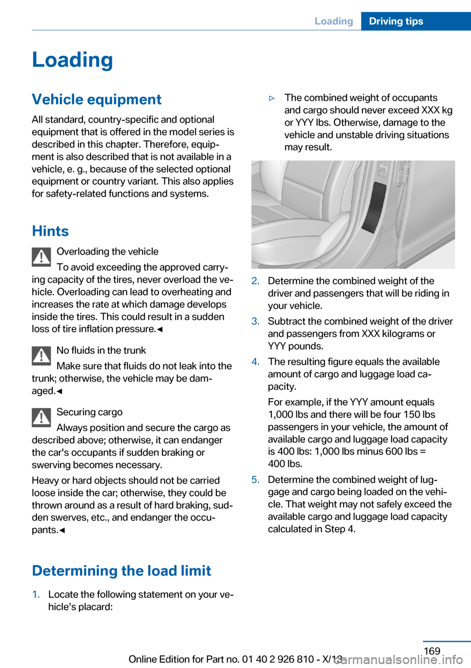
Determining the load limit1.Locate the following statement on your ve‐
hicle’s placard:▷The combined weight of occupants
and cargo should never exceed XXX kg
or YYY lbs. Otherwise, damage to the
vehicle and unstable driving situations
may result.2.Determine the combined weight of the
driver and passengers that will be riding in
your vehicle.3.Subtract the combined weight of the driver
and passengers from XXX kilograms or
YYY pounds.4.The resulting figure equals the available
amount of cargo and luggage load ca‐
pacity.
For example, if the YYY amount equals
1,000 lbs and there will be four 150 lbs
passengers in your vehicle, the amount of
available cargo and luggage load capacity
is 400 lbs: 1,000 lbs minus 600 lbs =
400 lbs.5.Determine the combined weight of lug‐
gage and cargo being loaded on the vehi‐
cle. That weight may not safely exceed the
available cargo and luggage load capacity
calculated in Step 4.Seite 169LoadingDriving tips169
Online Edition for Part no. 01 40 2 926 810 - X/13
Page 180 of 248

▷Energy recovery.▷Climate control output.▷Coasting.
Display ECO PRO tips
"ECO PRO Tips"
The setting is stored for the profile currently in
use.
Coasting
The concept
The system helps to conserve fuel.
To do this, under certain conditions the engine
is automatically decoupled from the transmis‐
sion when transmission position D is engaged.
The vehicle continues traveling with the engine
idling to reduce fuel consumption. Transmis‐
sion position D remains engaged.
This driving condition is referred to as coast‐
ing.
As soon as the brake or accelerator pedal is
depressed, the engine is automatically coupled
to the transmission again.
Hints Coasting is a component of the ECO PRO, re‐
fer to page 173, driving mode.
Coasting is automatically activated when ECO
PRO mode is called via the Driving Dynamics
Control.
The function is available in a certain speed
range.
A forward-looking driving style helps the driver
to use the function as often as possible and supports the fuel-conserving effect of coast‐
ing.
Safety mode
The function is not available if one of the fol‐ lowing conditions is satisfied.
▷DSC OFF or TRACTION activated.▷Driving in the dynamic limit range and on
steep uphill or downhill grades.▷Battery charge status temporarily too low
or vehicle electrical system drawing exces‐
sive current.▷Cruise control activated.
Functional requirements
In ECO PRO mode, this function is available in
a speed range from approximately 30 mph, ap‐
prox. 50 km/h to 100 mph, approx. 160 km/h, if
the following conditions are satisfied:
▷Accelerator pedal and brake pedal are not
operated.▷The selector lever is in transmission posi‐
tion D.▷Engine and transmission are at operating
temperature.
Display
Display in the instrument cluster The mark in the bar display be‐
low the tachometer is backlit in
blue and is located at the zero
point. The tachometer approxi‐
mately indicates idle speed.
The coasting point indicator is illuminated at
the zero point during coasting.
Indications on the Control Display
The Coasting driving condition is displayed in
EfficientDynamics Info while this driving mode
is active.
The distance traveled in the Coasting driving
condition is indicated by a counter.
Seite 176Driving tipsSaving fuel176
Online Edition for Part no. 01 40 2 926 810 - X/13