2013 BMW 3 SERIES SEDAN steering
[x] Cancel search: steeringPage 122 of 248

COMFORT/ECO PROBalanced control of the vehicle.
Variable sport steering The variable sport steering increases the
steering angle of the front wheels at large
steering wheel angles, e.g., in tight curves or
when parking. Steering becomes more direct.
It also varies the force required to turn the
wheels in accordance with the vehicle speed.
This results in a sporty steering response. In
addition, it becomes easier to steer during
parking and maneuvering.
Driving Dynamics Control The conceptThe Driving Dynamics Control can be used to
adjust the certain characteristics of the vehicle.
Various programs can be selected for this pur‐
pose. The Driving Dynamics Control and the
DSC OFF buttons can each be used to activate
a program.
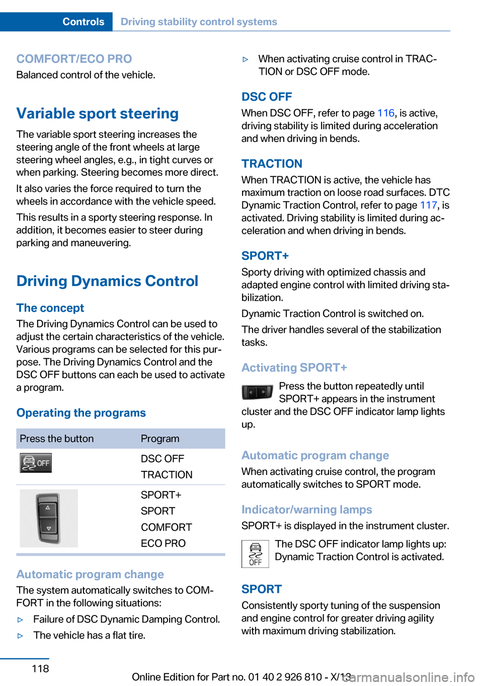
Operating the programsPress the buttonProgramDSC OFF
TRACTIONSPORT+
SPORT
COMFORT
ECO PRO
Automatic program change
The system automatically switches to COM‐
FORT in the following situations:
▷Failure of DSC Dynamic Damping Control.▷The vehicle has a flat tire.▷When activating cruise control in TRAC‐
TION or DSC OFF mode.
DSC OFF
When DSC OFF, refer to page 116, is active,
driving stability is limited during acceleration
and when driving in bends.
TRACTION When TRACTION is active, the vehicle has
maximum traction on loose road surfaces. DTC
Dynamic Traction Control, refer to page 117, is
activated. Driving stability is limited during ac‐
celeration and when driving in bends.
SPORT+
Sporty driving with optimized chassis and
adapted engine control with limited driving sta‐
bilization.
Dynamic Traction Control is switched on.
The driver handles several of the stabilization
tasks.
Activating SPORT+ Press the button repeatedly until
SPORT+ appears in the instrument
cluster and the DSC OFF indicator lamp lights
up.
Automatic program change When activating cruise control, the program
automatically switches to SPORT mode.
Indicator/warning lamps
SPORT+ is displayed in the instrument cluster.
The DSC OFF indicator lamp lights up:
Dynamic Traction Control is activated.
SPORT Consistently sporty tuning of the suspension
and engine control for greater driving agility
with maximum driving stabilization.
Seite 118ControlsDriving stability control systems118
Online Edition for Part no. 01 40 2 926 810 - X/13
Page 125 of 248

Driving comfortVehicle equipment
All standard, country-specific and optional
equipment that is offered in the model series is
described in this chapter. Therefore, equip‐
ment is also described that is not available in a
vehicle, e. g., because of the selected optional
equipment or country variant. This also applies
for safety-related functions and systems.
Active Cruise Control with Stop & Go function, ACC
The conceptThis system can be used to select a desired
speed that the vehicle will maintain automati‐
cally on clear roads.
To the extent possible, the system automati‐
cally adjusts the speed to a slower vehicle
ahead of you.
The distance that the vehicle maintains to the
vehicle ahead of you can be varied.
For safety reasons, it depends on the speed.
To maintain a certain distance, the system au‐
tomatically reduces the speed, applies the
brakes lightly, or accelerates again if the vehi‐
cle ahead begins moving faster.
If the vehicle ahead of you brakes to a halt, the
system is able to detect this within the given
system limits. If the vehicle ahead of your
drives away again from a halt, your vehicle is
able to accelerate if operated accordingly.
Even if some time passes before the vehicle
ahead of you drives away again, your own vehi‐
cle can still be accelerated automatically and
simply.
As soon as the road is clear, it accelerates to
the desired speed.The speed is also maintained on downhill gra‐
dients, but may not be maintained on uphill
slopes if engine power is insufficient.
General information
Depending on the set driving program, the
characteristics of the cruise control can
change in certain areas.
Hints Personal responsibility
Even an active system does not release
the driver from personal responsibility for the
driving process, especially for lane tracking,
adaptation of speed, distance and driving style
to the traffic conditions.
Because of technical system limits, the system
cannot independently react appropriately in all
traffic situations.
Monitor the driving process, the surrounding
area and what is occurring in traffic continu‐
ously and attentively and actively intervene as
required, e.g., by braking, steering or making an evasive maneuver.◀
Unfavorable weather conditions
In the event of unfavorable weather and
light conditions, e. g. if there is rain, snowfall,
slush, fog or glare, this may result in poorer
recognition of vehicles and lane limits as well
as short-term interruptions for vehicles that are
already detected. Drive attentively, and react to
the current traffic events. Intervene actively
when necessary, e.g., by braking, steering or
making an evasive maneuver, otherwise, there
is danger of an accident.◀Seite 121Driving comfortControls121
Online Edition for Part no. 01 40 2 926 810 - X/13
Page 126 of 248

At a glance
Buttons on the steering wheelPress the
buttonFunctionSystem on/off, interrupt, refer to
page 122Maintaining/storing the speed,
refer to page 123Resume speed, refer to
page 124Reduce distance, refer to
page 124Increase distance, refer to
page 124Rocker switch:
Maintaining/storing the speed,
refer to page 123
Changing, maintaining, and
storing the speed, refer to
page 123
The arrangement of the buttons varies accord‐
ing to the how the vehicle is equipped or coun‐
try-specific variants.
Radar sensor
A radar sensor is located in the front bumper
for detecting vehicles on the road ahead of the
vehicle.
A dirty or covered sensor may hinder the de‐
tection of vehicles.
▷If necessary, clean the radar sensor. Re‐
move layers of snow and ice carefully.▷Do not cover the view field of the radar
sensor.
Switching on/off and interrupting cruise control
Switching on Press the button on the steering
wheel.
The indicator lamps in the instrument cluster
light up and the mark in the speedometer is set
to the current speed.
Cruise control can be used.
Switching off Deactivated or interrupted system
If the system is deactivated or inter‐
rupted, actively intervene by braking, steering
and, if necessary, with evasive maneuvers; oth‐
erwise, there is the danger of an accident oc‐
curring.◀
If switching off the system while stationary,
press on the brake pedal at the same time.
Press the button.
▷If active: press twice.▷If interrupted: press once.Seite 122ControlsDriving comfort122
Online Edition for Part no. 01 40 2 926 810 - X/13
Page 132 of 248

Malfunction
The system cannot be activated if the radar
sensor is not aligned correctly. This may be
caused by damage incurred during parking, for
example.
A Check Control message is displayed if the
system fails.
Cruise control
The concept The system is functional at speeds beginning
at approx. 20 mph/30 km/h.
It maintains the speed that was set using the
control elements on the steering wheel.
The system brakes on downhill gradients if en‐
gine braking action is insufficient.
Unfavorable conditions
Do not use the system if unfavorable
conditions make it impossible to drive at a con‐
stant speed, for instance:▷On curvy roads.▷In heavy traffic.▷On slippery roads, in fog, snow or rain, or
on a loose road surface.
Otherwise, you could lose control of the vehi‐
cle and cause an accident.◀
General information
Depending on the set driving program, the
characteristics of the cruise control can
change in certain areas.
At a glance
Buttons on the steering wheelPress the buttonFunctionSystem on/off, interruptStore speedResume speedRocker switch: change,
hold, store speed
Controls
Switching on Press the button on the steering
wheel.
The marking in the speedometer is set to the
current speed.
Cruise control can be used.
Switching off Deactivated or interrupted system
If the system is deactivated or inter‐
rupted, actively intervene by braking and, if
necessary, with evasive maneuvers; otherwise,
there is the danger of an accident occurring.◀
Press the button.
▷If active: press twice.▷If interrupted: press once.
The displays go out. The stored desired speed
is deleted.
Interrupting When active, press the button.
The system is automatically interrupted if:
Seite 128ControlsDriving comfort128
Online Edition for Part no. 01 40 2 926 810 - X/13
Page 138 of 248

The rearview camera image is displayed. The
setting is stored for the remote control cur‐
rently in use.
Display on the Control Display
Functional requirement▷The rearview camera is switched on.▷The trunk lid is fully closed.
Activating the assistance functions
More than one assistance function can be ac‐
tive at the same time.
▷Parking aid lines
"Parking aid lines"
Pathway and turning circle lines are dis‐
played.
▷Obstacle marking
"Obstacle marking"
Spatially-shaped markings are displayed.
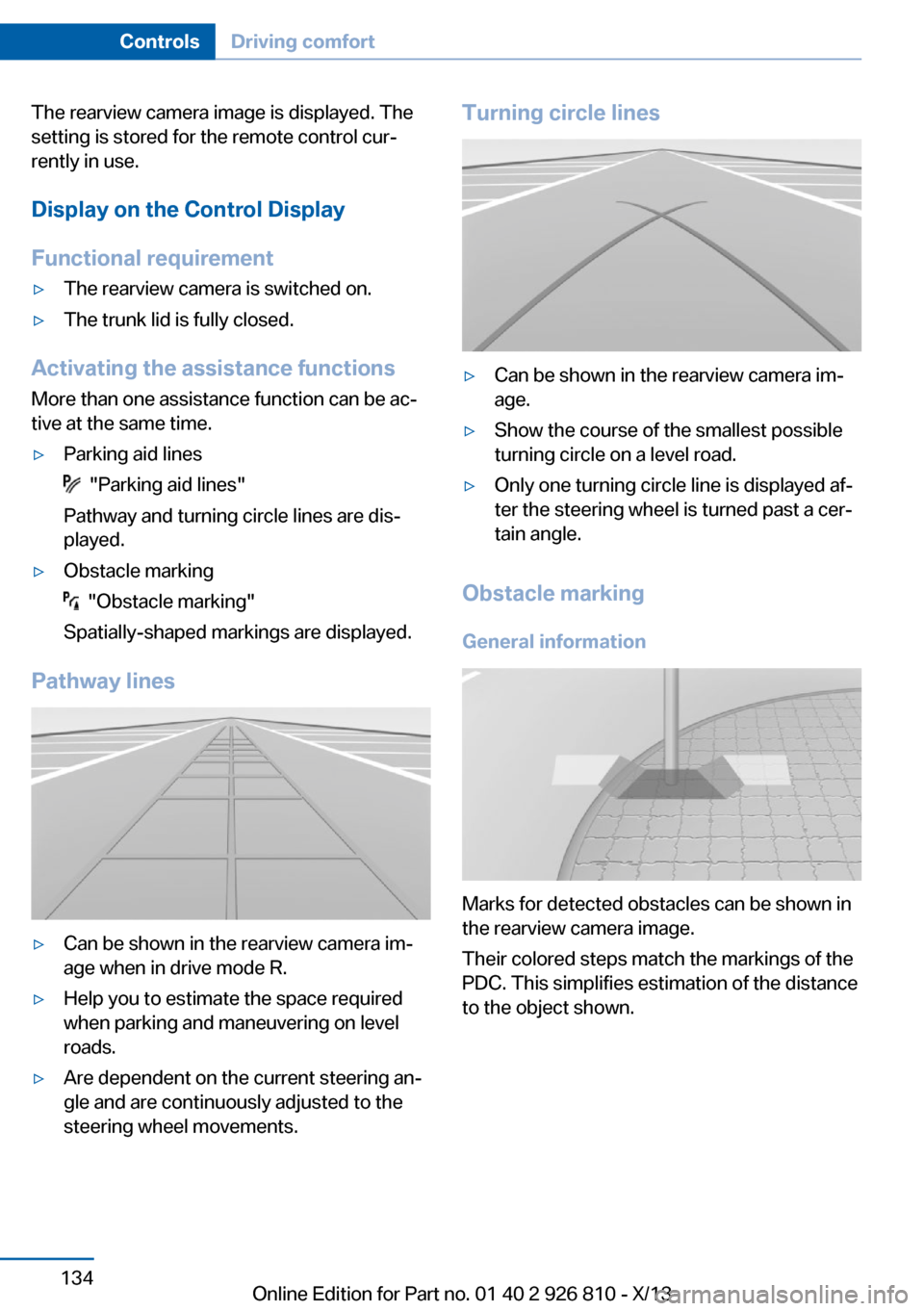
Pathway lines
▷Can be shown in the rearview camera im‐
age when in drive mode R.▷Help you to estimate the space required
when parking and maneuvering on level
roads.▷Are dependent on the current steering an‐
gle and are continuously adjusted to the
steering wheel movements.Turning circle lines▷Can be shown in the rearview camera im‐
age.▷Show the course of the smallest possible
turning circle on a level road.▷Only one turning circle line is displayed af‐
ter the steering wheel is turned past a cer‐
tain angle.
Obstacle marking
General information
Marks for detected obstacles can be shown in
the rearview camera image.
Their colored steps match the markings of the
PDC. This simplifies estimation of the distance
to the object shown.
Seite 134ControlsDriving comfort134
Online Edition for Part no. 01 40 2 926 810 - X/13
Page 139 of 248

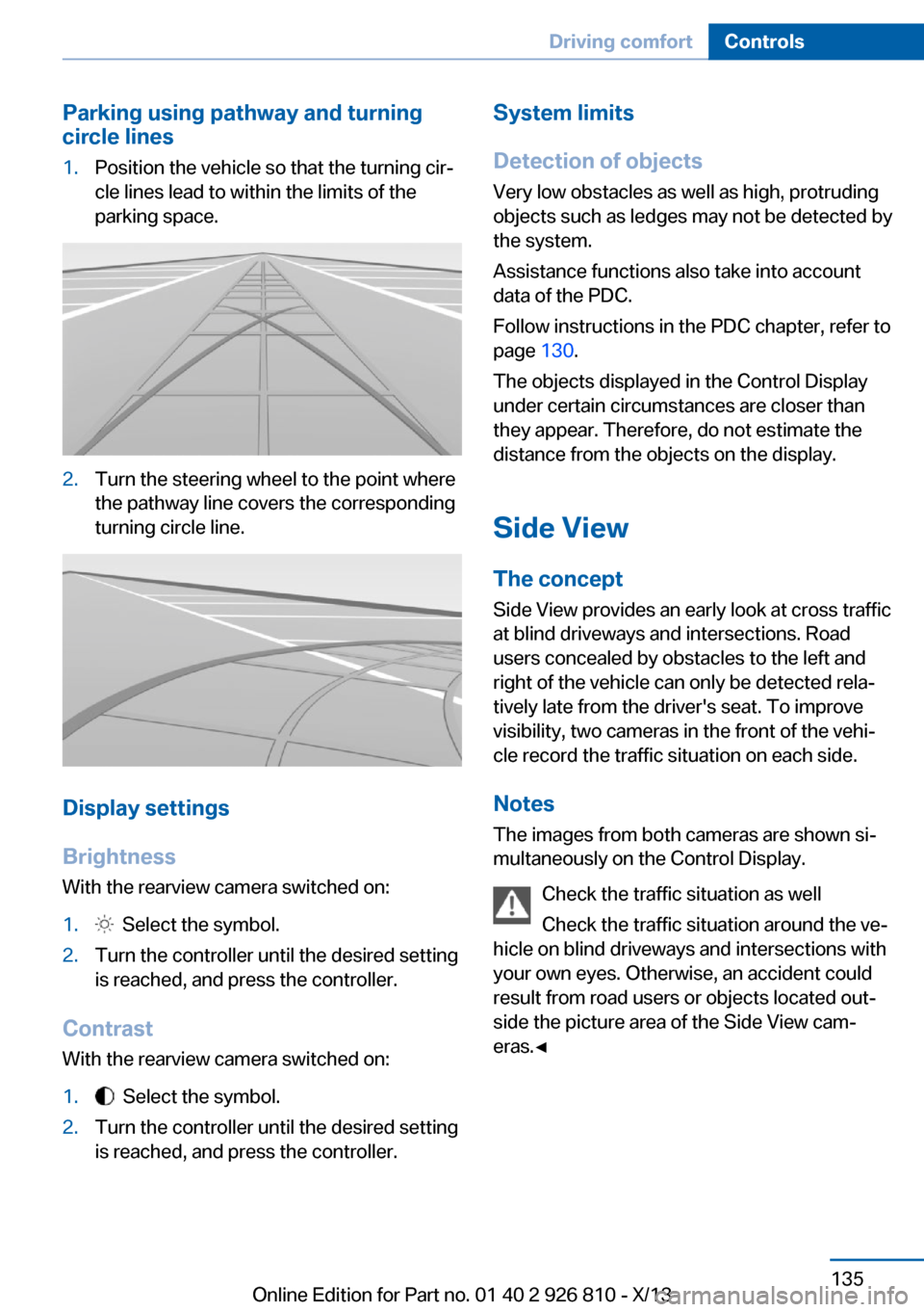
Parking using pathway and turning
circle lines1.Position the vehicle so that the turning cir‐
cle lines lead to within the limits of the
parking space.2.Turn the steering wheel to the point where
the pathway line covers the corresponding
turning circle line.
Display settings
Brightness
With the rearview camera switched on:
1. Select the symbol.2.Turn the controller until the desired setting
is reached, and press the controller.
Contrast
With the rearview camera switched on:
1. Select the symbol.2.Turn the controller until the desired setting
is reached, and press the controller.System limits
Detection of objects
Very low obstacles as well as high, protruding
objects such as ledges may not be detected by
the system.
Assistance functions also take into account
data of the PDC.
Follow instructions in the PDC chapter, refer to
page 130.
The objects displayed in the Control Display
under certain circumstances are closer than
they appear. Therefore, do not estimate the
distance from the objects on the display.
Side View The concept Side View provides an early look at cross traffic
at blind driveways and intersections. Road
users concealed by obstacles to the left and
right of the vehicle can only be detected rela‐
tively late from the driver's seat. To improve
visibility, two cameras in the front of the vehi‐
cle record the traffic situation on each side.
Notes The images from both cameras are shown si‐
multaneously on the Control Display.
Check the traffic situation as well
Check the traffic situation around the ve‐
hicle on blind driveways and intersections with
your own eyes. Otherwise, an accident could
result from road users or objects located out‐
side the picture area of the Side View cam‐
eras.◀Seite 135Driving comfortControls135
Online Edition for Part no. 01 40 2 926 810 - X/13
Page 142 of 248

The backup camera image is displayed. The
setting is stored for the remote control cur‐
rently in use.
Display
Visual warning The approach of the vehicle to an object can
be shown on the Control Display.
When the distance to an object is small, a red
bar is shown in front of the vehicle, as it is in
the PDC display.
The display appears as soon as Top View is
activated.
If the rearview camera image was selected last,
it again appears on the display when reverse
gear is selected. To switch to Top View:
"Rear view camera" Select the symbol on
the Control Display.
The setting is stored for the remote control
currently in use.
Brightness
With Top View switched on:
1. Select the symbol.2.Turn the controller until the desired setting
is reached, and press the controller.
Contrast
With Top View switched on:
1. Select the symbol.2.Turn the controller until the desired setting
is reached, and press the controller.Displaying the turning circle and
pathway lines▷The static, red turning circle line shows the
space needed to the side of the vehicle
when the steering wheel is turned all the
way.▷The variable, green pathway line assists
you in assessing the amount of space ac‐
tually needed to the side of the vehicle.
The lane line depends on the engaged
drive mode and the current steering angle.
The track line is continuously adjusted for
the steering wheel movement.
"Parking aid lines"
Turning circle and pathway lines are displayed.
System limits
Top View cannot be used in the following sit‐
uations:
▷With a door open.▷With the trunk lid open.▷With an exterior mirror folded in.▷In poor light.
A Check Control message is displayed in some
of these situations.
Parking assistant The concept
This system assists the driver in parking paral‐
lel to the road.
Seite 138ControlsDriving comfort138
Online Edition for Part no. 01 40 2 926 810 - X/13
Page 143 of 248

Ultrasound sensors measure parking spaces
on both sides of the vehicle.
The parking assistant calculates the best pos‐
sible parking line and takes control of steering
during the parking procedure.
When parking, also take note of the visual and
acoustic information and instructions issued
by the PDC, the parking assistant and the rear‐
view camera and react accordingly.
A component of the parking assistant is the
PDC Park Distance Control, refer to page 130.
Hints Personal responsibility
Even an active system does not relieve
the driver from personal responsibility for the
driving process.
Because of technical system limits, the system
cannot independently react appropriately in all
traffic situations.
Continuously and attentively monitor the driv‐
ing process, the area surrounding the vehicle
and the traffic situation, and actively intervene
when required, otherwise, there is a risk of an
accident.◀
Changes to the parking space
Changes to the parking space after it was
measured are not taken into account by the
system.
Therefore, always be alert and ready to inter‐
vene; otherwise, there is the danger of an acci‐
dent occurring.◀
Transporting loads
Loads that extend beyond the perimeter
of the vehicle are not taken into account by the
system during the parking procedure.
Therefore, always be alert and ready to inter‐
vene; otherwise, there is the danger of an acci‐
dent occurring.◀Curbs
The parking assistant may steer the vehi‐
cle over or onto curbs.
Therefore, always be alert and ready to inter‐
vene; otherwise, the wheels, tires, or the vehi‐
cle may become damaged.◀
An engine that has been switched off by the
Auto Start Stop function is restarted automati‐
cally when the parking assistant is activated.
Requirements
For measuring parking spaces▷Maximum speed while driving forward ap‐
prox. 22 mph/35 km/h.▷Maximum distance to row of parked vehi‐
cles: 5 ft/1.5 m.
Suitable parking space
▷Gap between two objects with a minimum
length of approx. 5 ft/1.5 m.▷Minimum length of the gap: own vehicle's
length plus approx. 4 ft/1.2 m.▷Minimum depth: approx. 5 ft/1.5 m.
For parking procedure
▷Doors and trunk lid closed.▷Parking brake released.▷When parking in parking spaces on the
driver's side, the corresponding turn signal
must be set where applicable.Seite 139Driving comfortControls139
Online Edition for Part no. 01 40 2 926 810 - X/13