2013 BMW 3 SERIES SEDAN Page 88
[x] Cancel search: Page 88Page 201 of 248

Do not exceed the maximum tire inflation pres‐
sure indicated on the side wall of the tire.
Run-flat tires
Label
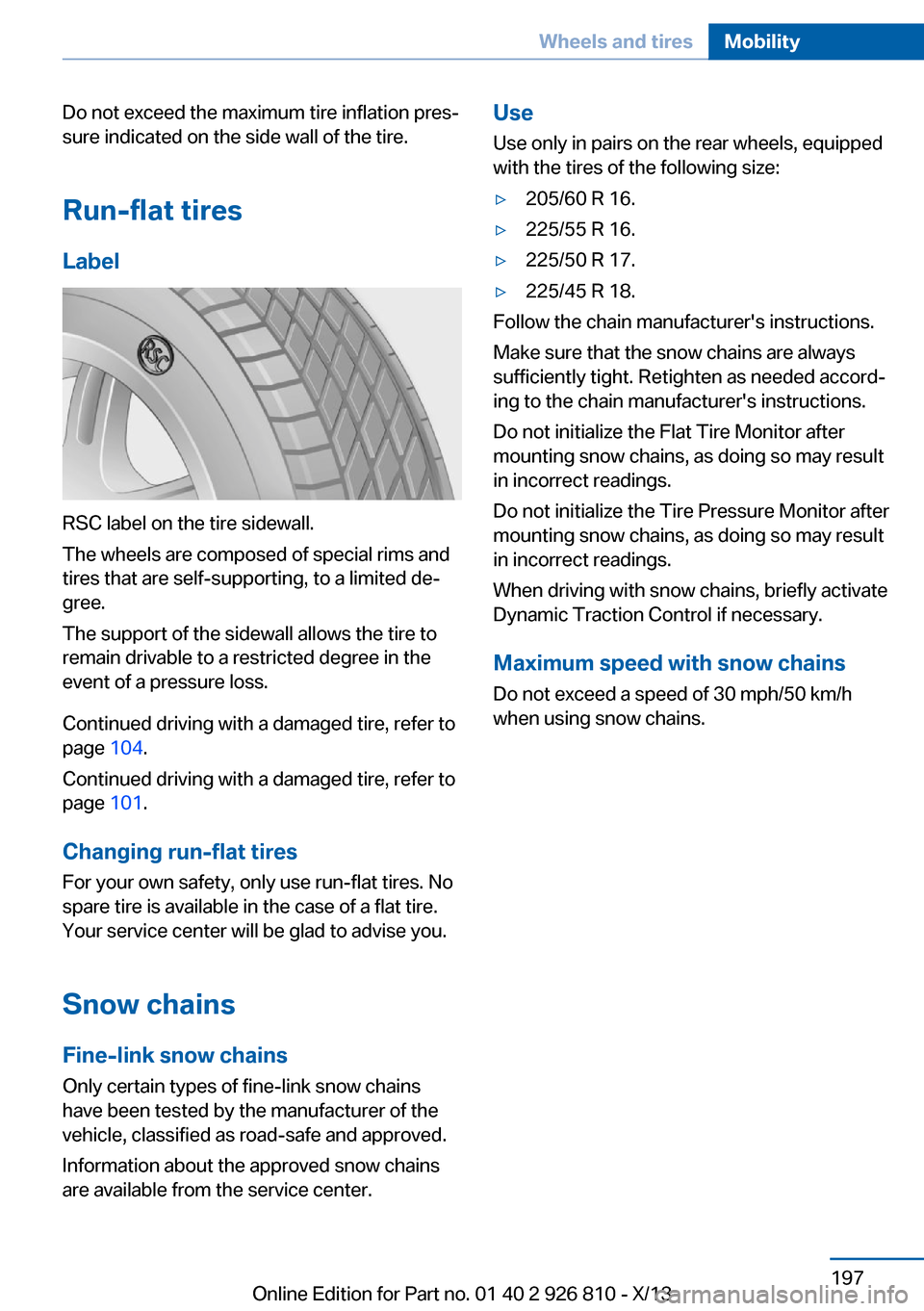
RSC label on the tire sidewall.
The wheels are composed of special rims and
tires that are self-supporting, to a limited de‐
gree.
The support of the sidewall allows the tire to
remain drivable to a restricted degree in the
event of a pressure loss.
Continued driving with a damaged tire, refer to
page 104.
Continued driving with a damaged tire, refer to
page 101.
Changing run-flat tires
For your own safety, only use run-flat tires. No
spare tire is available in the case of a flat tire.
Your service center will be glad to advise you.
Snow chains
Fine-link snow chains
Only certain types of fine-link snow chains
have been tested by the manufacturer of the
vehicle, classified as road-safe and approved.
Information about the approved snow chains
are available from the service center.
Use
Use only in pairs on the rear wheels, equipped
with the tires of the following size:▷205/60 R 16.▷225/55 R 16.▷225/50 R 17.▷225/45 R 18.
Follow the chain manufacturer's instructions.
Make sure that the snow chains are always
sufficiently tight. Retighten as needed accord‐
ing to the chain manufacturer's instructions.
Do not initialize the Flat Tire Monitor after
mounting snow chains, as doing so may result
in incorrect readings.
Do not initialize the Tire Pressure Monitor after
mounting snow chains, as doing so may result
in incorrect readings.
When driving with snow chains, briefly activate
Dynamic Traction Control if necessary.
Maximum speed with snow chains Do not exceed a speed of 30 mph/50 km/h
when using snow chains.
Seite 197Wheels and tiresMobility197
Online Edition for Part no. 01 40 2 926 810 - X/13
Page 204 of 248

Engine oilVehicle equipment
All standard, country-specific and optional
equipment that is offered in the model series is
described in this chapter. Therefore, equip‐
ment is also described that is not available in a
vehicle, e. g., because of the selected optional
equipment or country variant. This also applies
for safety-related functions and systems.
General information The engine oil consumption is dependent on
the driving style and driving conditions. When
a sporty driving style is used, the engine oil
consumption, for example, is clearly higher.
Therefore, regularly check the engine oil level
after refueling.
The vehicle is equipped with electronic oil
measurement.
The electronic oil measurement has two meas‐
uring principles.▷Status display▷Detailed measurement
Checking the oil level
electronically
Status display
The concept The oil level is monitored electronically during
driving and shown on the Control Display.
If the oil level reaches the minimum level, a
check control message is displayed.
Requirements A current measured value is available after ap‐
prox. 30 minutes of driving. During a shorter
trip, the status of the last, sufficiently long trip
is displayed.
With frequent short-distance trips, regularly perform a detailed measurement.
Displaying the oil level1."Vehicle Info"2."Vehicle status"3. "Engine oil level"
Oil level display messages
Different messages appear on the display de‐
pending on the oil level. Pay attention to these
messages.
If the engine oil level is too low, within the next
125 miles/200 km Add oil, refer to page 201.
Engine oil level too low
Add oil immediately; otherwise, an insuf‐
ficient amount of engine oil could result in en‐
gine damage.◀
Take care not to add too much engine oil. Too much engine oil
Have the vehicle checked immediately;
otherwise, surplus oil can lead to engine dam‐
age.◀
Detailed measurement
The concept
In the detailed measurement the oil level is
checked and displayed via a scale.
During the measurement, the idle speed is in‐
creased somewhat.
General information
A detailed measurement is only possible with
certain engines.
Seite 200MobilityEngine oil200
Online Edition for Part no. 01 40 2 926 810 - X/13
Page 208 of 248

MaintenanceVehicle equipment
All standard, country-specific and optional
equipment that is offered in the model series is
described in this chapter. Therefore, equip‐
ment is also described that is not available in a
vehicle, e. g., because of the selected optional
equipment or country variant. This also applies
for safety-related functions and systems.
BMW maintenance system The maintenance system indicates required
maintenance measures, and thereby provides
support in maintaining road safety and the op‐ erational reliability of the vehicle.
Condition Based Service
CBS
Sensors and special algorithms take into ac‐
count the driving conditions of your vehicle.
Based on this, Condition Based Service deter‐
mines the maintenance requirements.
The system makes it possible to adapt the
amount of maintenance you need to your user
profile.
Detailed information on service requirements,
refer to page 82, can be displayed on the Con‐
trol Display.
Service data in the remote control Information on the required maintenance is
continuously stored in the remote control. Your service center will read out this data and
suggest the right array of service procedures
for your vehicle.
Therefore, hand your service specialist the re‐
mote control with which the vehicle was driven
most recently.Storage periods
Storage periods during which the vehicle bat‐
tery was disconnected are not taken into ac‐
count.
If this occurs, have a service center update the
time-dependent maintenance procedures,
such as checking brake fluid and, if necessary,
changing the engine oil and the microfilter/
activated-charcoal filter.
Service and Warranty Information Booklet for US
models and Warranty and
Service Guide Booklet for
Canadian models
Please consult your Service and Warranty In‐
formation Booklet for US models and Warranty
and Service Guide Booklet for Canadian mod‐ els for additional information on service re‐
quirements.
Maintenance and repair should be performed
by your service center. Make sure to have reg‐
ular maintenance procedures recorded in the
vehicle's Service and Warranty Information
Booklet for US models, and in the Warranty
and Service Guide Booklet for Canadian mod‐
els. These entries are proof of regular mainte‐
nance.
Socket for OBD Onboard
Diagnosis
Note Socket for Onboard Diagnosis
The socket for onboard diagnostics may
only be used by the service center or a work‐
shop that operates in accordance with the
specifications of the vehicle manufacturer withSeite 204MobilityMaintenance204
Online Edition for Part no. 01 40 2 926 810 - X/13
Page 210 of 248

Replacing componentsVehicle equipmentAll standard, country-specific and optional
equipment that is offered in the model series is
described in this chapter. Therefore, equip‐
ment is also described that is not available in a
vehicle, e. g., because of the selected optional
equipment or country variant. This also applies
for safety-related functions and systems.
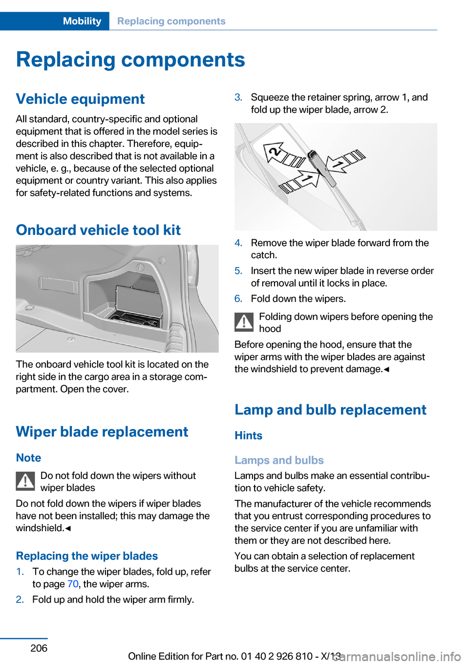
Onboard vehicle tool kit
The onboard vehicle tool kit is located on the
right side in the cargo area in a storage com‐
partment. Open the cover.
Wiper blade replacement Note Do not fold down the wipers without
wiper blades
Do not fold down the wipers if wiper blades
have not been installed; this may damage the
windshield.◀
Replacing the wiper blades
1.To change the wiper blades, fold up, refer
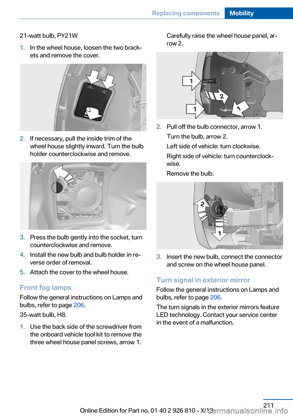
to page 70, the wiper arms.2.Fold up and hold the wiper arm firmly.3.Squeeze the retainer spring, arrow 1, and
fold up the wiper blade, arrow 2.4.Remove the wiper blade forward from the
catch.5.Insert the new wiper blade in reverse order
of removal until it locks in place.6.Fold down the wipers.
Folding down wipers before opening the hood
Before opening the hood, ensure that the
wiper arms with the wiper blades are against
the windshield to prevent damage.◀
Lamp and bulb replacement
Hints
Lamps and bulbs Lamps and bulbs make an essential contribu‐
tion to vehicle safety.
The manufacturer of the vehicle recommends
that you entrust corresponding procedures to
the service center if you are unfamiliar with
them or they are not described here.
You can obtain a selection of replacement
bulbs at the service center.
Seite 206MobilityReplacing components206
Online Edition for Part no. 01 40 2 926 810 - X/13
Page 212 of 248

Accessing the turn signals and low beams
Follow the general instructions on Lamps and
bulbs, refer to page 206.1.In the wheel house, loosen the two brack‐
ets and remove the cover.
Turn signal
21-watt bulb, PY21W
1.If necessary, pull the inside trim of the
wheel house slightly inward. Turn the bulb
holder counterclockwise and remove.2.Press the bulb gently into the socket, turn
counterclockwise and remove.3.Install the new bulb and bulb holder in re‐
verse order of removal.4.Attach the cover to the wheel house.Low beams
55-watt bulb, H7.1.Turn the cap counterclockwise and re‐
move.2.Tilt the bulb down and then up to loosen it
from the holder and remove.3.Pull the connector off the bulb.4.Attach the connector to the new bulb.5.First insert the bulb at the top with the
strap, arrow 1, and then press down firmly,
arrow 2. Make sure that the bulb snaps into
place.6.Close the headlamp housing with the cap.
Make sure that the cap engages.7.Attach the cover to the wheel house.Seite 208MobilityReplacing components208
Online Edition for Part no. 01 40 2 926 810 - X/13
Page 213 of 248

Accessing the daytime running lights, high
beams/headlamp flasher and parking
lamps
Follow the general instructions on Lamps and
bulbs, refer to page 206.1.Open the hood, refer to page 199.2.Turn the cap counterclockwise and re‐
move.
Parking lamps
6-watt bulb, H6W.
1.Turn the bulb holder counterclockwise and
remove.2.Press the bulb gently into the socket, turn
counterclockwise and remove.3.To insert the bulb and bulb holder, proceed
in reverse order of removal. Make sure that
the bulb holder snaps into place.4.Close the headlamp housing with the cap.
Make sure that the cap engages.High beams/headlamp flasher
55-watt bulb, H7.1.Tilt the bulb down and then up to loosen it
from the holder and remove.2.Pull the connector off the bulb.3.Attach the connector to the new bulb.4.First insert the bulb at the top with the
strap, arrow 1, and then press down firmly,
arrow 2. Make sure that the bulb snaps into
place.5.Close the headlamp housing with the cap.
Make sure that the cap engages.Seite 209Replacing componentsMobility209
Online Edition for Part no. 01 40 2 926 810 - X/13
Page 214 of 248

Daytime running lights
24-watt bulb, PW24W.1.If necessary, remove the high beam bulb
connector.2.Remove the bulb holder.3.Remove the bulb from the bulb holder.4.To insert the new bulb, proceed in reverse
order of removal. During insertion, the bot‐
tom of the bulb holder must be facing
downward. Make sure that the bulb holder
snaps into place.5.Attach the high beam bulb connector.6.Close the headlamp housing with the cap.
Make sure that the cap engages.
Xenon headlamps
Xenon headlamps
Because of the long life of these bulbs, the
likelihood of failure is very low. Switching the
lamps on and off frequently shortens their life.
If a bulb fails, switch on the front fog lamps and
continue the trip with great care. Comply with
local regulations.
Do not perform work/bulb replacement
on xenon headlamps
Have any work on the xenon lighting system,
including bulb replacement, performed only by
a service center. Due to the high voltage
present in the system, there is the danger of
fatal injuries if work is carried out improperly.◀
For checking and adjusting headlamp aim,
please contact your BMW center.
Headlamps1Parking lamps / daytime running lights2Low beams/high beams/headlamp flasher3Turn signal
Low beams and high beams are designed with
xenon technology.
The parking lamps and daylight running lights
are made using LED technology.
Contact your service center in the event of a
malfunction.
Turn signal
Follow the general instructions on Lamps and
bulbs, refer to page 206.
Seite 210MobilityReplacing components210
Online Edition for Part no. 01 40 2 926 810 - X/13
Page 215 of 248

21-watt bulb, PY21W1.In the wheel house, loosen the two brack‐
ets and remove the cover.2.If necessary, pull the inside trim of the
wheel house slightly inward. Turn the bulb
holder counterclockwise and remove.3.Press the bulb gently into the socket, turn
counterclockwise and remove.4.Install the new bulb and bulb holder in re‐
verse order of removal.5.Attach the cover to the wheel house.
Front fog lamps
Follow the general instructions on Lamps and
bulbs, refer to page 206.
35-watt bulb, H8.
1.Use the back side of the screwdriver from
the onboard vehicle tool kit to remove the
three wheel house panel screws, arrow 1.Carefully raise the wheel house panel, ar‐
row 2.2.Pull off the bulb connector, arrow 1.
Turn the bulb, arrow 2.
Left side of vehicle: turn clockwise.
Right side of vehicle: turn counterclock‐
wise.
Remove the bulb.3.Insert the new bulb, connect the connector
and screw on the wheel house panel.
Turn signal in exterior mirror
Follow the general instructions on Lamps and
bulbs, refer to page 206.
The turn signals in the exterior mirrors feature
LED technology. Contact your service center
in the event of a malfunction.
Seite 211Replacing componentsMobility211
Online Edition for Part no. 01 40 2 926 810 - X/13