2013 BMW 135I COUPE clock
[x] Cancel search: clockPage 15 of 284

14
At a glanceDashboard
Instrument cluster
1Speedometer
135i: with fuel gauge
2 Indicator lamps for turn signals
3 Indicator and warning lamps 15
4 Tachometer 76
5 Fuel gauge 76
135i: engine oil temperature 76
6 Display for
>Clock 75
> Outside temperature 75
> Indicator and warning lamps 847
Display for
>Position of automatic transmission 64
> Gear indicator of 7-gear Sport automatic
transmission with double clutch 66
> Computer 77
> Date of next scheduled service, and
remaining distance to be driven 80
> Odometer and trip odometer 75
> High-beam Assistant 102
> Checking the oil level 233
> Settings and information 79
8 Resetting the trip odometer 75
00320051004F004C00510048000300280047004C0057004C005200510003
Page 24 of 284
23
iDrive
At a glance
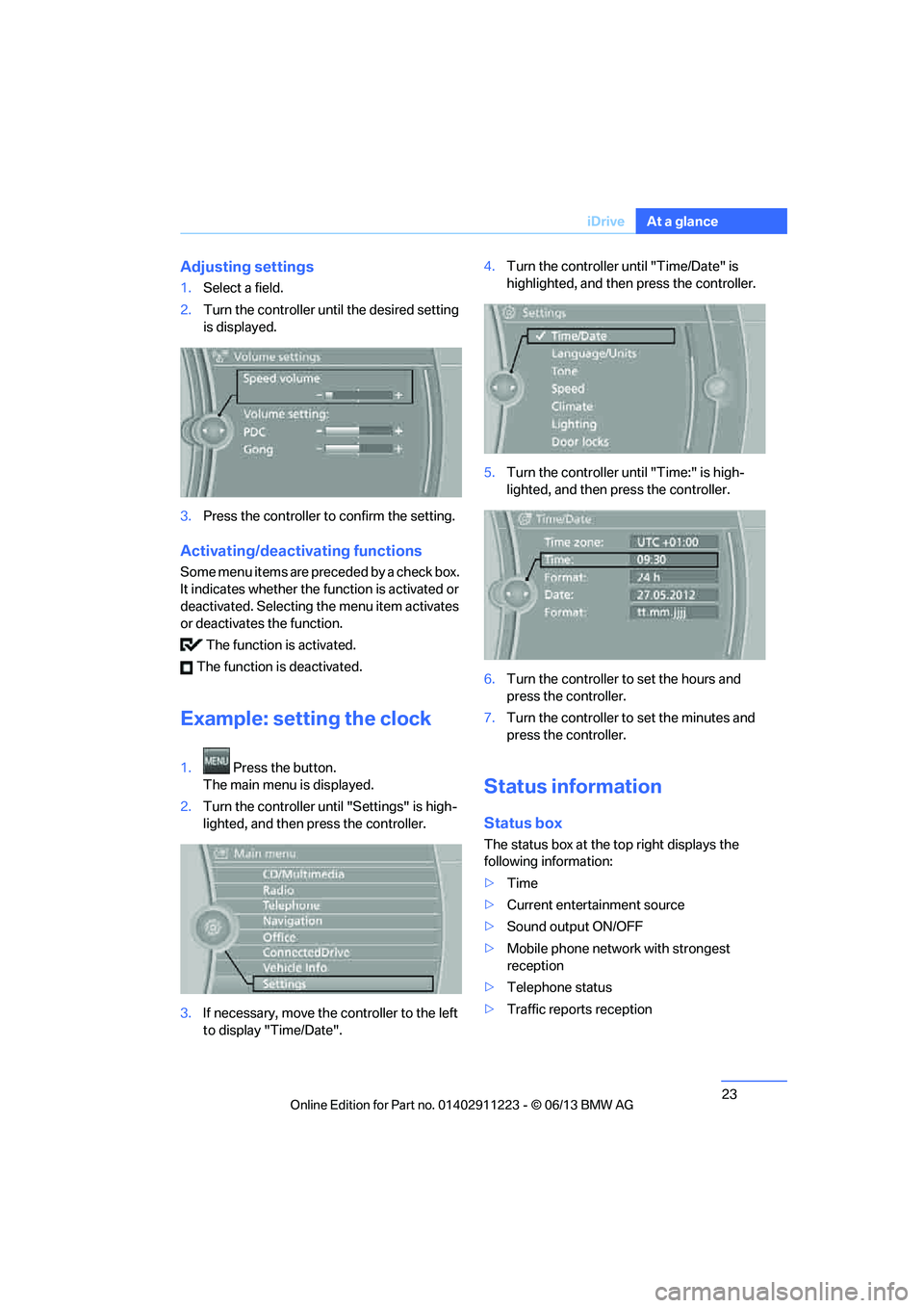
Adjusting settings
1.
Select a field.
2. Turn the controller until the desired setting
is displayed.
3. Press the controller to confirm the setting.
Activating/deactivating functions
Some menu items are preceded by a check box.
It indicates whether the fu nction is activated or
deactivated. Selecting the menu item activates
or deactivates the function.
The function is activated.
The function is deactivated.
Example: setting the clock
1. Press the button.
The main menu is displayed.
2. Turn the controller until "Settings" is high-
lighted, and then press the controller.
3. If necessary, move the controller to the left
to display "Time/Date". 4.
Turn the controller until "Time/Date" is
highlighted, and then press the controller.
5. Turn the controller until "Time:" is high-
lighted, and then press the controller.
6. Turn the controller to set the hours and
press the controller.
7. Turn the controller to set the minutes and
press the controller.
Status information
Status box
The status box at the top right displays the
following information:
> Time
> Current entertainment source
> Sound output ON/OFF
> Mobile phone network with strongest
reception
> Telephone status
> Traffic reports reception
00320051004F004C00510048000300280047004C0057004C005200510003
Page 34 of 284
33
Opening and closing
Controls
mum of four remote cont
rols. They are stored
for two remote controls if Comfort Access is in
use.
Personal Profile settings
For more information on specific settings, refer
to the specified pages.
> Programming the Programmable memory
keys, refer to page 25
> Response of the central locking system
when the car is unlocked, refer to page 34
> Automatic locking of th e vehicle, refer to
page 37
> Automatic call-up of th e driver's seat posi-
tion, refer to page 54
> Triple turn signal activation, refer to
page 71
> Settings for the display on the Control
Display and in the instrument cluster:
>12h/24h format of the clock, refer to
page 82
> Date format, refer to page 84
> Brightness of the Control Display, refer
to page 87
> Language of the Contro l Display, refer to
page 87
> Units of measure for fuel consumption,
distance covered/remaining distances,
and temperature, refer to page 80
> Show visual warning for Park Distance
Control PDC, refer to page 88
> Light settings:
>Welcome lamps, refer to page 101
> Pathway lighting, refer to page 101
> Daytime running lights, refer to
page 101
> High-beam Assistant, refer to page 102
> Automatic climate control: activating/deac-
tivating AUTO program, air conditioning
and automatic recirculated air control,
setting temperature, air volume and
distribution, refer to page 107 ff>
Entertainment:
>Tone control, refer to page 155
> Speed-dependent volume control, refer
to page 156
Central locking system
The concept
The central locking system functions when the
driver's door is closed.
The system simultaneously engages and
releases the locks on the following:
>Doors
> Trunk lid
> Fuel filler flap
Operating from outside
>Via the remote control
> Using the door lock
> In cars with Comfort Access, via the handles
on the driver's door or the front passenger
door
At the same time as locking and unlocking via
the remote control:
> Welcome lights, the inte rior light, and the
courtesy lighting are switched on or off.
> Alarm system, refer to page 38, is armed or
disarmed.
Operating from inside
By means of the button fo r central locking, refer
to page 37.
In the event of a sufficien tly severe accident, the
central locking system unlocks automatically. In
addition, the hazard warning flashers and inte-
rior lamps come on.
00320051004F004C00510048000300280047004C0057004C005200510003
Page 50 of 284
49
Adjustments
Controls
Adjustments
Vehicle equipment
In this chapter, all production, country, and
optional equipment that is offered in the model
range is described. As a result, some equip-
ment described may not be
available in a partic-
ular vehicle, for example due to the options or
national-market version selected. This also
applies to safety related functions and systems.
Sitting safely
The ideal sitting position can make a vital
contribution to relaxed, fatigue-free driving. In
conjunction with the sa fety belts, the head
restraints and the airbags, the seated position
has a major influence on your safety in the event
of an accident. To ensu re that the safety sys-
tems operate with optimal efficiency, we
strongly urge you to observe the instructions
contained in the following section.
For additional information on transporting
children safely, refer to page 58.
Airbags
Always maintain an adequate distance
between yourself and the airbags. Always
grip the steering wheel on the rim, with your
hands in the 3 o'clock and 9 o'clock positions,
to minimize the risk of injury to the hands or
arms in the event of the airbag being triggered
off.
No one and nothing should come between the
airbags and the seat occupant.
Do not use the cover of the front airbag on the
front passenger side as a storage area. Make
sure that the front passeng er is sitting correctly,
i.e. not resting feet or legs on the dashboard;
otherwise, leg injuries ca n occur if the front air-
bag deploys.
Make sure that passen gers keep their heads
away from the side airbag and do not lean against the cover of the
head airbag; otherwise,
serious injuries can result if the airbag
deploys. <
Even if you follow all the instructions, injuries
resulting from contact with airbags cannot be
fully excluded, depending on the circum-
stances. The ignition and inflation noise may
provoke a mild hearing loss in extremely
sensitive individuals. This effect is usually only
temporary.
For airbag locations and additional information
on airbags, refer to page 97.
Head restraint
A correctly adjusted head restraint reduces the
risk of neck injury in the event of an accident.
Adjust the head restraint in such a way
that its center is at approx. ear level.
Otherwise, there is an incr eased risk of injury in
the event of an accident. <
Head restraints, refer to page 52.
Safety belt
Before every drive, make sure that all occupants
wear their safety belts. Airbags complement the
safety belt as an additi onal safety device, but
they do not represent a substitute.
Your vehicle has four se ats, each of which is
equipped with a safety belt.
Never allow more than one person to
wear a single safety belt. Never allow
infants or small children to ride in a passenger's
lap. Make sure that the be lt in the lap area sits
low across the hips and does not press against
the abdomen.
The safety belt must not rest against the throat,
run across sharp edges, pass over hard or frag-
ile objects or be pinched. Fasten the safety belt
so that it sits as snugly as possible against the
lap and shoulder without being twisted. Other-
wise, the belt could slide over your hips and
00320051004F004C00510048000300280047004C0057004C005200510003
Page 76 of 284

75
Controls overview
Controls
Controls overview
Vehicle equipment
In this chapter, all production, country, and
optional equipment that is offered in the model
range is described. For this reason, descrip-
tions will be given of some equipment that may
not be available in a vehi
cle, for example due to
the special options or national-market version
selected. This also app lies to safety related
functions and systems.
Odometer, outside
temperature display, clock
1 Knob in the instrument cluster
2 Outside temperature and clock
3 Odometer and trip odometer
Knob in the instrument cluster
>To reset the trip odomet er while the ignition
is switched on
> To display the time, outside temperature
and odometer briefly while the ignition is
switched off
Units of measure
To select the respective units of measure, miles
or km for the odometer as well as 7 or 6 for
the outside temperature, refer to Units of mea-
sure on page 80.
The setting is stored for the remote control
currently in use.
Time, outside temperature display
Setting the time, refer to page 82.
Outside temperature warning
When the displayed temperature sinks to
approx. +377/+3 6, a signal sounds and a
warning lamp lights up. There is an increased
risk of black ice.
Black ice can also form at temperatures
above +37 7/+3 6. You should there-
fore drive carefully on bridges and shaded
roads, for example; otherwise, there is an
increased risk of an accident. <
Odometer and trip odometer
Resetting the trip odometer:
With the ignition switched on, press button 1 in
the instrument cluster.
When the vehicle is parked
If you still want to view the time, outside tem-
perature and odometer reading briefly after the
remote control has been taken out of the igni-
tion lock:
Press button 1 in the instrument cluster.
00320051004F004C00510048000300280047004C0057004C005200510003
Page 83 of 284
82
ControlsControls overview
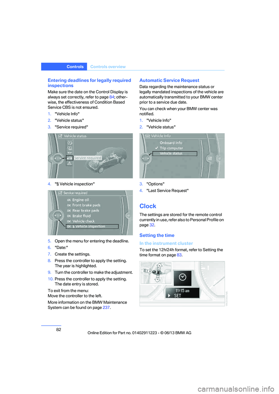
Entering deadlines for legally required
inspections
Make sure the date on the Control Display is
always set correctly, refer to page 84; other-
wise, the effectiveness of Condition Based
Service CBS is not ensured.
1. "Vehicle Info"
2. "Vehicle status"
3. "Service required"
4. "§ Vehicle inspection"
5. Open the menu for entering the deadline.
6. "Date:"
7. Create the settings.
8. Press the controller to apply the setting.
The year is highlighted.
9. Turn the controller to make the adjustment.
10. Press the controller to apply the setting.
The date entry is stored.
To exit from the menu:
Move the controller to the left.
More information on the BMW Maintenance
System can be found on page 237.
Automatic Service Request
Data regarding the ma intenance status or
legally mandated inspecti ons of the vehicle are
automatically transmitted to your BMW center
prior to a service due date.
You can check when your BMW center was
notified.
1. "Vehicle Info"
2. "Vehicle status"
3. "Options"
4. "Last Service Request"
Clock
The settings are stored for the remote control
currently in use, refer also to Personal Profile on
page 32.
Setting the time
In the instrument cluster
To set the 12h/24h format , refer to Setting the
time format on page 83.
00320051004F004C00510048000300280047004C0057004C005200510003
Page 221 of 284
220
MobilityRefueling
Refueling
Vehicle equipment
In this chapter, all pr oduction, country, and
optional equipment that is offered in the model
range is described. For this reason, descrip-
tions will be given of some equipment that may
not be available in a vehi cle, for example due to
the special options or national-market version
selected. This also app lies to safety related
functions and systems.
General information
Refuel as soon as possible once your
cruising range falls below 30 miles/
50 km; otherwise, engine functions are not
ensured and damage can occur. <
Always switch off the engine before refu-
eling; otherwise, fuel cannot be added to
the tank and a message will be displayed. <
Take all precautionary measures and
observe all applicable regulations when
handling fuel. Do not carry any spare fuel con-
tainers in your vehicle. They can develop a leak
and cause an explosion or cause a fire in the
event of an accident. <
Fuel filler flap
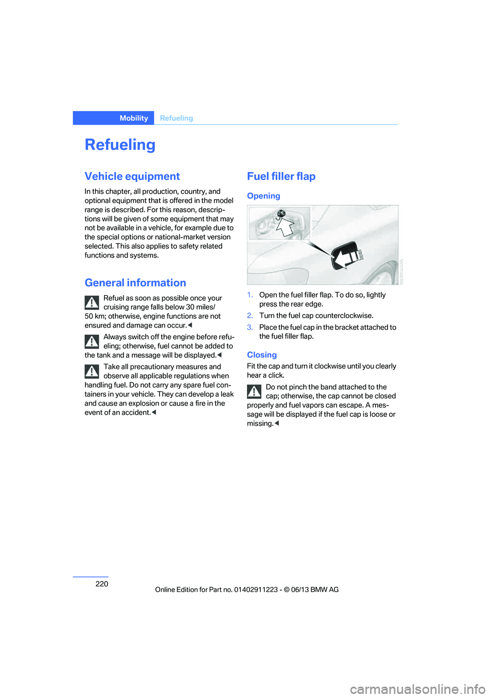
Opening
1.Open the fuel filler flap. To do so, lightly
press the rear edge.
2. Turn the fuel cap counterclockwise.
3. Place the fuel cap in th e bracket attached to
the fuel filler flap.
Closing
Fit the cap and turn it cl ockwise until you clearly
hear a click.
Do not pinch the band attached to the
cap; otherwise, the cap cannot be closed
properly and fuel vapors can escape. A mes-
sage will be displayed if the fuel cap is loose or
missing. <
00320051004F004C00510048000300280047004C0057004C005200510003
Page 237 of 284
236
MobilityEngine compartment
Coolant temperature
If the coolant and therefore the engine over-
heats, a warning lamp lights up. A message
appears on the Control Display.
Checking coolant level
Do not add coolant to the cooling system
when the engine is ho t. Escaping coolant
can cause burns. <
1. Do not open the engine hood before the
engine has cooled down.
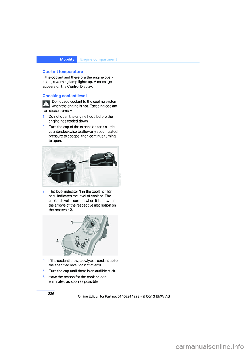
2. Turn the cap of the expansion tank a little
counterclockwise to allow any accumulated
pressure to escape, th en continue turning
to open.
3. The level indicator 1 in the coolant filler
neck indicates the level of coolant. The
coolant level is correct when it is between
the arrows of the respective inscription on
the reservoir 2.
4. If the coolant is low, sl owly add coolant up to
the specified level; do not overfill.
5. Turn the cap until there is an audible click.
6. Have the reason for the coolant loss
eliminated as so on as possible.
00320051004F004C00510048000300280047004C0057004C005200510003