2013 BMW 128I COUPE lights
[x] Cancel search: lightsPage 73 of 284

72
ControlsDriving
Switching on wipers
Press the lever upward, arrow 1.
The lever automatically returns to its initial
position when released.
Normal wiper speed
Press once.
The system switches to operation in the inter-
mittent mode when the vehicle is stationary.
Fast wiper speed
Press twice or press beyond the resistance
point.
The system switches to normal speed when the
vehicle is stationary.
Intermittent wipe or rain sensor
If the car is not equipped with a rain sensor, the
intermittent-wipe time is a preset.
If the car is equipped with a rain sensor, the time
between wipes is contro lled automatically and
depends on the intensity of the rainfall. The rain
sensor is mounted on the windshield, directly in
front of the interior rearview mirror.
Activating intermittent wipe or rain
sensor
Press the button, arrow 3. The LED in the
button lights up.
Setting speed for intermittent wipe or
sensitivity of the rain sensor
Turn the thumb wheel 5.
Deactivating intermit tent wipe or rain
sensor
Press the button again, arrow 3.
The LED goes out.
Deactivate the rain sensor before enter-
ing an automatic car wash. Failure to do
so could result in damage caused by undesired
wiper activation. <
Cleaning windshield and headlamps
Pull the lever, arrow 4.
Washer fluid is sprayed onto the windshield and
the wipers are operated for a short time.
When the vehicle lighting system is switched
on, the headlamps are cleaned at regular and
appropriate intervals.
Do not use the washers if there is any
danger that the flui d will freeze on the
windshield. If you do, your vision could be
obscured. Antifreeze should therefore be
added to the fluid, refer to Washer fluid.
Do not use the washers when the washer fluid
reservoir is empty; othe rwise, you will damage
the washer pump. <
Windshield washer nozzles
Both windshield washer nozzles are automati-
cally heated with the engine running or the
ignition switched on.
Washer fluid
Washer fluid antifree ze is flammable.
Therefore, keep it away from ignition
sources and only store it in the closed original
container that is kept out of reach of children;
otherwise, there is a risk of personal injury.
Comply with the instructions on the
container. <
00320051004F004C00510048000300280047004C0057004C005200510003
Page 76 of 284

75
Controls overview
Controls
Controls overview
Vehicle equipment
In this chapter, all production, country, and
optional equipment that is offered in the model
range is described. For this reason, descrip-
tions will be given of some equipment that may
not be available in a vehi
cle, for example due to
the special options or national-market version
selected. This also app lies to safety related
functions and systems.
Odometer, outside
temperature display, clock
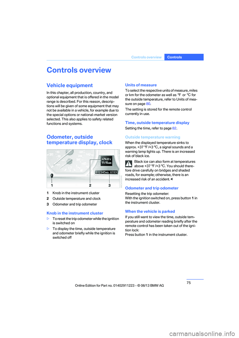
1 Knob in the instrument cluster
2 Outside temperature and clock
3 Odometer and trip odometer
Knob in the instrument cluster
>To reset the trip odomet er while the ignition
is switched on
> To display the time, outside temperature
and odometer briefly while the ignition is
switched off
Units of measure
To select the respective units of measure, miles
or km for the odometer as well as 7 or 6 for
the outside temperature, refer to Units of mea-
sure on page 80.
The setting is stored for the remote control
currently in use.
Time, outside temperature display
Setting the time, refer to page 82.
Outside temperature warning
When the displayed temperature sinks to
approx. +377/+3 6, a signal sounds and a
warning lamp lights up. There is an increased
risk of black ice.
Black ice can also form at temperatures
above +37 7/+3 6. You should there-
fore drive carefully on bridges and shaded
roads, for example; otherwise, there is an
increased risk of an accident. <
Odometer and trip odometer
Resetting the trip odometer:
With the ignition switched on, press button 1 in
the instrument cluster.
When the vehicle is parked
If you still want to view the time, outside tem-
perature and odometer reading briefly after the
remote control has been taken out of the igni-
tion lock:
Press button 1 in the instrument cluster.
00320051004F004C00510048000300280047004C0057004C005200510003
Page 80 of 284

79
Controls overview
Controls
Settings and information
Operating principle
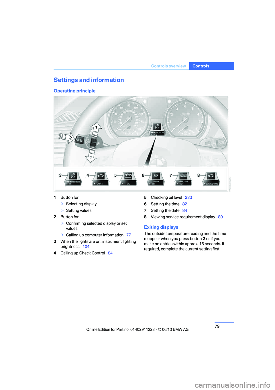
1
Button for:
>Selecting display
> Setting values
2 Button for:
>Confirming selected display or set
values
> Calling up computer information 77
3 When the lights are on: instrument lighting
brightness 104
4 Calling up Check Control 845
Checking oil level 233
6 Setting the time 82
7 Setting the date 84
8 Viewing service re quirement display 80
Exiting displays
The outside temperature reading and the time
reappear when you press button 2 or if you
make no entries within approx. 15 seconds. If
required, complete the current setting first.
00320051004F004C00510048000300280047004C0057004C005200510003
Page 87 of 284

86
ControlsControls overview
2.Press button 2.
"CHECK OK" appears if there are no Check
Control messages. If a Check Control mes-
sage has been stored, the corresponding
lamp lights up. It is accompanied by a text
message on the Control Display.
3. Push button 1 to check for other messages.
4. Press button 2.
The display again shows the outside
temperature and the time.
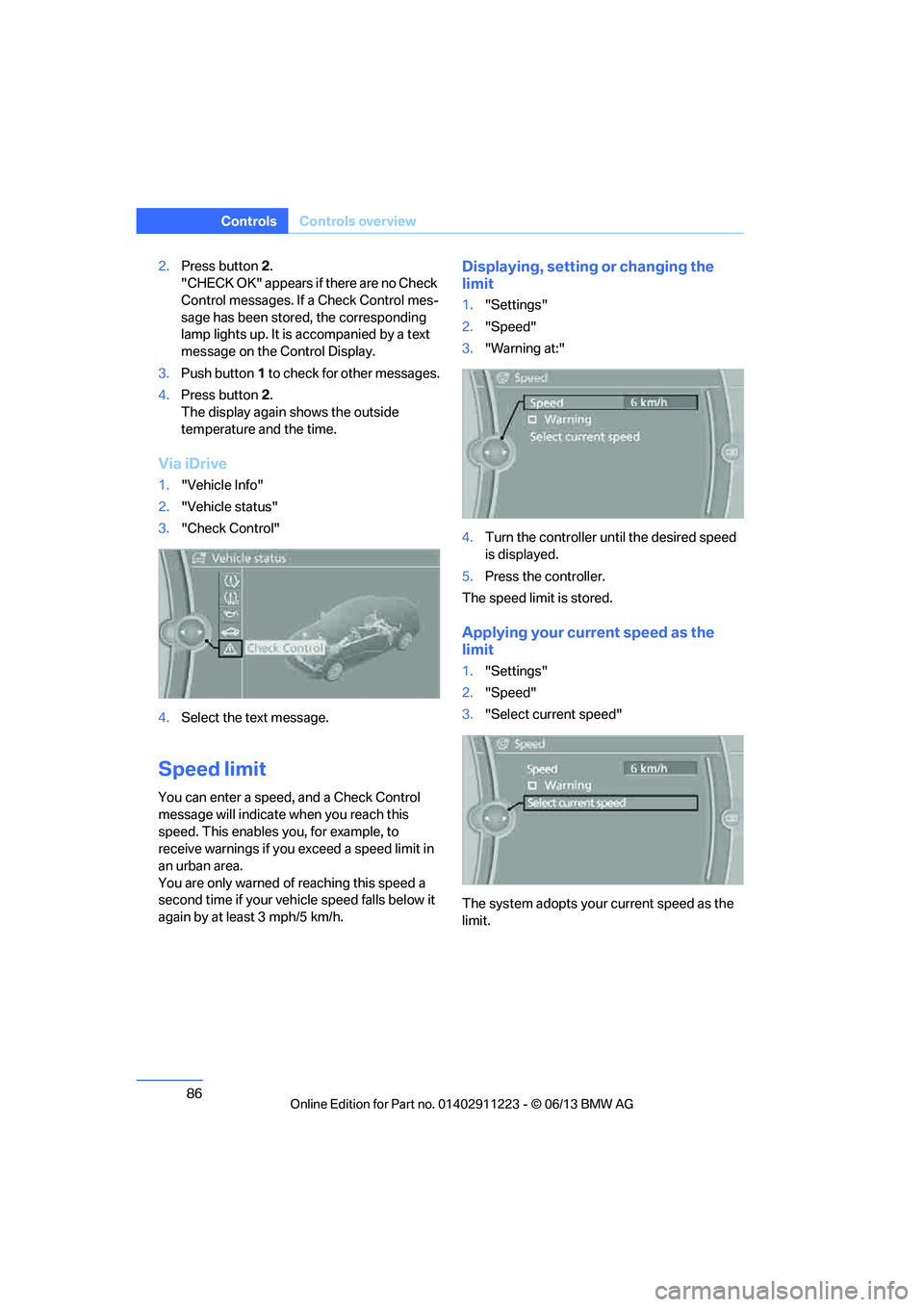
Via iDrive
1. "Vehicle Info"
2. "Vehicle status"
3. "Check Control"
4. Select the text message.
Speed limit
You can enter a speed, and a Check Control
message will indicate when you reach this
speed. This enables you, for example, to
receive warnings if you exceed a speed limit in
an urban area.
You are only warned of reaching this speed a
second time if your vehi cle speed falls below it
again by at least 3 mph/5 km/h.
Displaying, setting or changing the
limit
1. "Settings"
2. "Speed"
3. "Warning at:"
4. Turn the controller until the desired speed
is displayed.
5. Press the controller.
The speed limit is stored.
Applying your curr ent speed as the
limit
1. "Settings"
2. "Speed"
3. "Select current speed"
The system adopts your current speed as the
limit.
00320051004F004C00510048000300280047004C0057004C005200510003
Page 89 of 284

88
ControlsTechnology for driving comfort and safety
Technology for driving comfort and safety
Vehicle equipment
In this chapter, all pr oduction, country, and
optional equipment that is offered in the model
range is described. For this reason, descrip-
tions will be given of some equipment that may
not be available in a vehi cle, for example due to
the special options or national-market version
selected. This also app lies to safety related
functions and systems.
Park Distance Control PDC
The concept
The PDC assists you with maneuvering in tight
parking spaces. Acoustic signals and a visual
indicator warn you of the presence of an object
behind your vehicle. Four ultrasonic sensors in
the bumper measure the distance.
These sensors have a range of approx. 6.5 ft/
2 m. However, an acoustic warning does not
sound until an object is approx. 24 in/60 cm
from the corner sensors or approx. 5 ft/1.50 m
from the center sensors.
PDC is a parking aid that can indicate
objects when they are approached
slowly, as is usually th e case when parking.
Avoid approaching an object at high speed; oth-
erwise, physical circumstances may lead to the
system warning being issued too late. <
Switching on automatically
With the engine running or the ignition switched
on, the system is activated after approx. second
when you engage reverse gear or move the
automatic transmission selector lever to
position R. Wait this short period before driving.
Switching off automatically
After approx. 164 ft/50 m of driving or above
approx. 18 mph/30 km/h, the system switches
off and the LED goes out.
Signal tones
When nearing an object, its position is indicated
correspondingly by an in terval tone. As the dis-
tance between vehicle an d object decreases,
the intervals betwee n the tones become
shorter. If the distance to the nearest object
falls to below roughly 1 ft/30 cm, then a contin-
uous tone sounds.
An interval tone is interrupted after approx.
3seconds:
> If you stop in front of an object that has been
detected by only one of the corner sensors
> If you are driving parallel to a wall
Malfunction
The warning lamp lights up. A mes-
sage appears on the Control Display.
PDC is malfunctioning. Have the
system checked.
To avoid this problem, keep the sensors clean
and free of ice or snow in order to ensure that
they will continue to op erate effectively. When
using a high-pressure cleaner, do not spray the
sensors for extended periods of time and only
from a distance of at least 1 ft/30 cm.
PDC with visual warning
The approach of the vehicle to an object is
shown on the Control Display. Objects that are
farther away are displayed on the Control Dis-
play before a signal tone sounds. The display
appears on the Control Display as soon as PDC
is activated.
00320051004F004C00510048000300280047004C0057004C005200510003
Page 90 of 284

89
Technology for driving comfort and safety
Controls
System limitations
Even with PDC, final responsibility for
estimating the distance between the
vehicle and any obstructions always remains
with the driver. Even when sensors are pro-
vided, there is a blind spot in which objects can
no longer be detected. The system is also sub-
ject to the physical limit s that apply to all forms
of ultrasonic measurement, such as those
encountered with traile r towbars and hitches,
thin or wedge-shaped objects, etc. Low objects
that have already been displayed, e.g. curbs,
can disappear again from the detection area of
the sensors before or after a continuous tone
sounds. Higher, protruding objects, e.g. ledges,
cannot be detected. Loud sound sources out-
side or inside the car can drown out the PDC
signal. Therefore, always drive cautiously; oth-
erwise, there is a risk of personal injury or prop-
erty damage. <
Driving stability control
systems
Your BMW has a number of systems that help
to maintain the vehicle's stability even in
adverse driving conditions.
Antilock Brake System ABS
ABS prevents locking of the wheels during
braking. Safe steering response is maintained
even during full braking. Active safety is thus
increased.
The ABS is operational every time you start the
engine. Braking safely, refer to page 126.
Electronic brake-force distribution
EBV
The system controls the brake pressure in the
rear wheels to ensure stable braking behavior.
Dynamic Brake Control DBC
When you apply the brakes rapidly, this system
automatically produces the maximum braking
force boost and thus helps to achieve the short-
est possible braking distance during full brak-
ing. This system exploi ts all of the benefits
provided by ABS.
Do not reduce the pressu re on the brake for the
duration of the full braking application.
Dynamic Stability Control DSC
DSC prevents the driving wheels from losing
traction when you pull aw ay from rest or accel-
erate. The system also recognizes unstable
driving conditions, for example if the rear of the
car is about to swerve or if momentum is acting
at an angle past the front wheels. In these
cases, DSC helps the vehicle maintain a safe
course within physical limits by reducing engine
output and through brakin g actions at the indi-
vidual wheels.
The laws of physics cannot be repealed,
even with DSC. An appropriate driving
style always remains th e responsibility of the
driver. Therefore, do no t reduce the additional
s a f e t y m a r g i n a g a i n b y t a k i n g r i s k s , a s t h i s c o u l d
result in an accident. <
Deactivating DSC
Press the button for at least 3 seconds until the
indicator lamp for DSC OFF lights up and DSC
OFF is displayed in the instrument cluster.
Dynamic Traction Cont rol DTC and DSC have
been simultaneously de activated. Stabilizing
and drive-output promoting actions are no
longer executed.
00320051004F004C00510048000300280047004C0057004C005200510003
Page 91 of 284

90
ControlsTechnology for driving comfort and safety
In the same way as with a differential interlock,
even if DSC is deactivated, brake actions are
still performed on the rear axle to enhance drive
output if the drive whee ls experience a signifi-
cant loss of traction.
To increase vehicle stability, activate DSC again
as soon as possible.
Activating DSC
Press the button again; th e indicator lamp in the
instrument cluster goes out.
For better control
If the indicator lamp flashes: the DSC
controls the driving and braking forces.
If the indicator lamp lights up: DSC and
DTC have failed.
The indicator lamp lights up and
DSC OFF is displayed in the instrument
cluster: DSC is deactivated.
Dynamic Traction Control DTC
DTC is a version of DSC in which the drive out-
put is optimized for part icular road conditions,
e.g. unplowed snow-covered roads. The sys-
tem assures the maximal drive output, but with
reduced driving stability. It is therefore neces-
sary to drive with appropriate caution.
You may find it useful to briefly activate DTC
under the following sp ecial circumstances:
> When driving uphill on snow-covered roads,
in slush or on unplowed, snow-covered
roads
> When rocking a stuck vehicle free or start-
ing off in deep snow or on loose ground
> When driving with snow chains
Activating DTC
Press the button; the indicator lamp for DSC
OFF lights up and TRACTION is displayed in
the instrument cluster.
For better control
If the indicator lamp flashes: DTC con-
trols the driving and braking forces.
If the indicator lamp lights up: DSC and
DTC have failed.
The indicator lamp lights up and TRAC-
TION is displayed in the instrument
cluster: DTC is activated.
Deactivating DTC
Press the button again; th e indicator lamp in the
instrument cluster goes out.
Drive-off assistant
The drive-off assistant enables you to drive off
smoothly on uphill gradients. It is not necessary
to use the parking brake for this.
1. Hold the car in place by depressing the
brake.
2. Release the brake and drive off without
delay.
The drive-off assistant holds the car in
place for approx. 2 seconds after the
brake is released. Drive off without delay after
releasing the brake. Otherwise, the drive-off
assistant will no longer hold the car in place
after approx. 2 seconds and the car will start to
roll backwards. <
00320051004F004C00510048000300280047004C0057004C005200510003
Page 96 of 284

95
Technology for driving comfort and safety
Controls
Message for unsuc
cessful system
reset
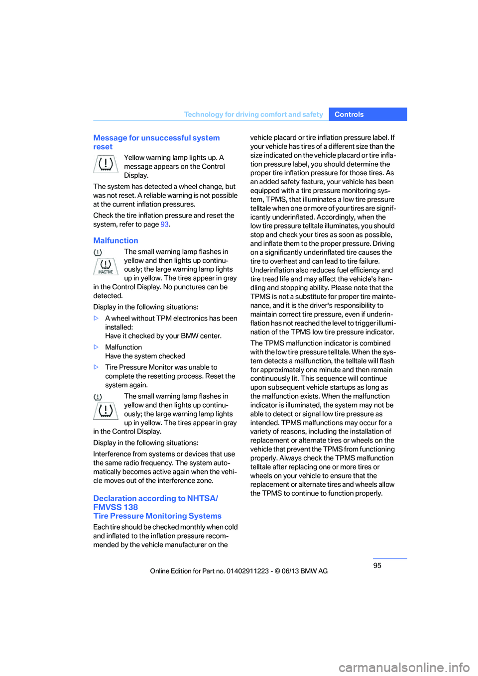
Yellow warning lamp lights up. A
message appears on the Control
Display.
The system has detected a wheel change, but
was not reset. A reliable warning is not possible
at the current inflation pressures.
Check the tire inflation pressure and reset the
system, refer to page 93.
Malfunction
The small warning lamp flashes in
yellow and then lights up continu-
ously; the large warning lamp lights
up in yellow. The tires appear in gray
in the Control Display. No punctures can be
detected.
Display in the following situations:
> A wheel without TPM electronics has been
installed:
Have it checked by your BMW center.
> Malfunction
Have the system checked
> Tire Pressure Monitor was unable to
complete the resetting process. Reset the
system again.
The small warning lamp flashes in
yellow and then lights up continu-
ously; the large warning lamp lights
up in yellow. The tires appear in gray
in the Control Display.
Display in the following situations:
Interference from systems or devices that use
the same radio frequency. The system auto-
matically becomes active again when the vehi-
cle moves out of the interference zone.
Declaration according to NHTSA/
FMVSS 138
Tire Pressure Monitoring Systems
Each tire should be checked monthly when cold
and inflated to the inflation pressure recom-
mended by the vehicle manufacturer on the vehicle placard or tire infl
ation pressure label. If
your vehicle has tires of a different size than the
size indicated on the vehi cle placard or tire infla-
tion pressure label, you should determine the
proper tire inflation pressure for those tires. As
an added safety feature, your vehicle has been
equipped with a tire pr essure monitoring sys-
tem, TPMS, that illuminate s a low tire pressure
t e l l t a l e w h e n o n e o r m o r e o f y o u r t i r e s a r e s i g n i f -
icantly underinflated. Accordingly, when the
low tire pressure telltal e illuminates, you should
stop and check your tires as soon as possible,
and inflate them to the proper pressure. Driving
on a significantly underinflated tire causes the
tire to overheat and ca n lead to tire failure.
Underinflation also reduces fuel efficiency and
tire tread life and may a ffect the vehicle's han-
dling and stopping ability. Please note that the
TPMS is not a substitute for proper tire mainte-
nance, and it is the driver's responsibility to
maintain correct tire pr essure, even if underin-
flation has not reached th e level to trigger illumi-
nation of the TPMS low tire pressure indicator.
The TPMS malfunction indicator is combined
with the low tire pressure telltale. When the sys-
tem detects a malfunction, the telltale will flash
for approximately one minute and then remain
continuously lit. This sequence will continue
upon subsequent vehicle startups as long as
the malfunction exists. When the malfunction
indicator is illuminated, the system may not be
able to detect or signal low tire pressure as
intended. TPMS malfunctions may occur for a
variety of reasons, includ ing the installation of
replacement or alternate tires or wheels on the
vehicle that prevent the TPMS from functioning
properly. Always check the TPMS malfunction
telltale after replacing one or more tires or
wheels on your vehicle to ensure that the
replacement or alternate tires and wheels allow
the TPMS to continue to function properly.
00320051004F004C00510048000300280047004C0057004C005200510003