Page 55 of 198

3-5
PRE-OPERATION INSPECTION AND MAINTENANCE
PRE-OPERATION INSPECTION AND MAINTENANCE
Before riding for break-in operation, practice or a race, make sure the machine is in good operating condition.
Before using this machine, check the following points.
GENERAL INSPECTION AND MAINTENANCE
Item Routine Page
CoolantCheck that coolant is filled up to the radiator cap. Check the cool-
ing system for leakage.P.3-6 – 7
FuelCheck that a fresh gasoline is filled in the fuel tank. Check the fuel
line for leakage.P.1-13
Engine oilCheck that the oil level is correct. Check the crankcase and oil line
for leakage.P.3-9 – 10
Gear shifter and clutchCheck that gears can be shifted correctly in order and that the
clutch operates smoothly.P.3-7
Throttle grip/HousingCheck that the throttle grip operation and free play are correctly
adjusted. Lubricate the throttle grip and housing, if necessary.P.3-7 – 8
Brakes Check the play of front brake and effect of front and rear brake. P.3-14 – 16
Drive chainCheck drive chain slack and alignment. Check that the drive chain
is lubricated properly.P.3-17 – 18
WheelsCheck for excessive wear and tire pressure. Check for loose
spokes and have no excessive play.P.3-20 – 21
SteeringCheck that the handlebar can be turned smoothly and have no ex-
cessive play.P.3-21 – 22
Front forks and rear shock
absorberCheck that they operate smoothly and there is no oil leakage.
P.3-18 – 20
Cables (wires)Check that the clutch and throttle cables move smoothly. Check
that they are not caught when the handlebars are turned or when
the front forks travel up and down.—
Exhaust pipe Check that the exhaust pipe is tightly mounted and has no cracks. P.4-3 – 6
Rear wheel sprocket Check that the rear wheel sprocket tightening bolt is not loose. P.3-17
Lubrication Check for smooth operation. Lubricate if necessary. P.3-23
Bolts and nuts Check the chassis and engine for loose bolts and nuts. P.1-15
Lead connectorsCheck that the CDI magneto, CDI unit, and ignition coil are con-
nected tightly.P.1-7
SettingsIs the machine set suitably for the condition of the racing course
and weather or by taking into account the results of test runs be-
fore racing? Are inspection and maintenance completely done?P.7-1 – 10
Page 126 of 198

4-52
CDI MAGNETO
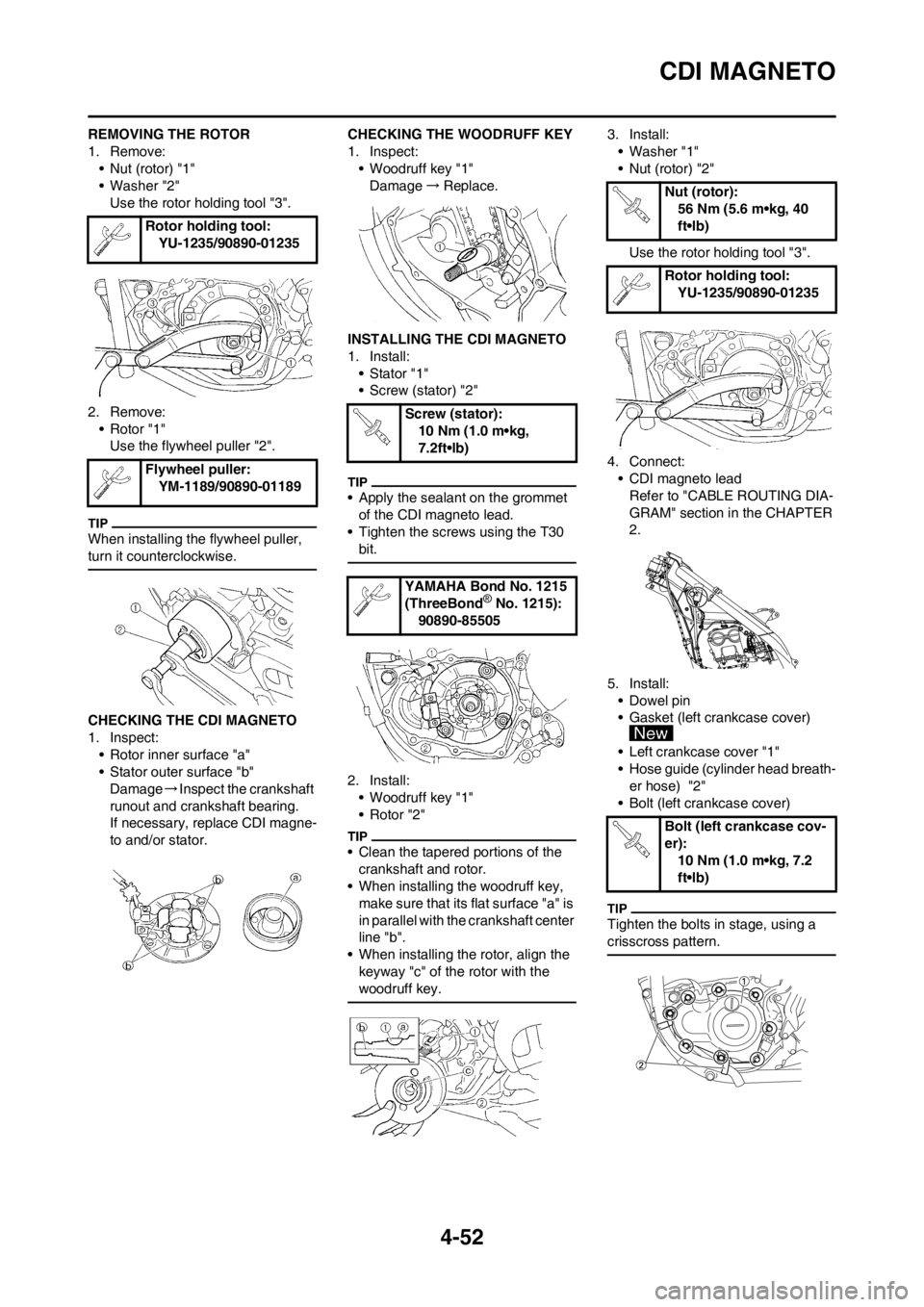
REMOVING THE ROTOR
1. Remove:
• Nut (rotor) "1"
• Washer "2"
Use the rotor holding tool "3".
2. Remove:
• Rotor "1"
Use the flywheel puller "2".
When installing the flywheel puller,
turn it counterclockwise.
CHECKING THE CDI MAGNETO
1. Inspect:
• Rotor inner surface "a"
• Stator outer surface "b"
Damage→Inspect the crankshaft
runout and crankshaft bearing.
If necessary, replace CDI magne-
to and/or stator.CHECKING THE WOODRUFF KEY
1. Inspect:
• Woodruff key "1"
Damage→Replace.
INSTALLING THE CDI MAGNETO
1. Install:
• Stator "1"
• Screw (stator) "2"
• Apply the sealant on the grommet
of the CDI magneto lead.
• Tighten the screws using the T30
bit.
2. Install:
• Woodruff key "1"
• Rotor "2"
• Clean the tapered portions of the
crankshaft and rotor.
• When installing the woodruff key,
make sure that its flat surface "a" is
in parallel with the crankshaft center
line "b".
• When installing the rotor, align the
keyway "c" of the rotor with the
woodruff key.
3. Install:
• Washer "1"
• Nut (rotor) "2"
Use the rotor holding tool "3".
4. Connect:
• CDI magneto lead
Refer to "CABLE ROUTING DIA-
GRAM" section in the CHAPTER
2.
5. Install:
• Dowel pin
• Gasket (left crankcase cover)
• Left crankcase cover "1"
• Hose guide (cylinder head breath-
er hose) "2"
• Bolt (left crankcase cover)
Tighten the bolts in stage, using a
crisscross pattern.
Rotor holding tool:
YU-1235/90890-01235
Flywheel puller:
YM-1189/90890-01189
Screw (stator):
10 Nm (1.0 m•kg,
7.2ft•lb)
YAMAHA Bond No. 1215
(ThreeBond
® No. 1215):
90890-85505
Nut (rotor):
56 Nm (5.6 m•kg, 40
ft•lb)
Rotor holding tool:
YU-1235/90890-01235
Bolt (left crankcase cov-
er):
10 Nm (1.0 m•kg, 7.2
ft•lb)
Page 143 of 198

5-4
FRONT WHEEL AND REAR WHEEL
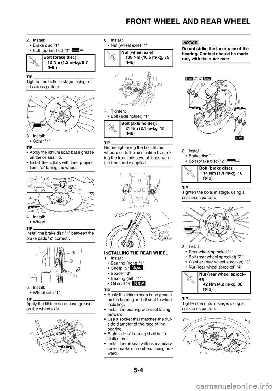
2. Install:
• Brake disc "1"
• Bolt (brake disc) "2"
Tighten the bolts in stage, using a
crisscross pattern.
3. Install:
•Collar "1"
• Apply the lithium soap base grease
on the oil seal lip.
• Install the collars with their projec-
tions "a" facing the wheel.
4. Install:
• Wheel
Install the brake disc "1" between the
brake pads "2" correctly.
5. Install:
• Wheel axle "1"
Apply the lithium soap base grease
on the wheel axle.
6. Install:
• Nut (wheel axle) "1"
7. Tighten:
• Bolt (axle holder) "1"
Before tightening the bolt, fit the
wheel axle to the axle holder by strok-
ing the front fork several times with
the front brake applied.
INSTALLING THE REAR WHEEL
1. Install:
• Bearing (right) "1"
• Circlip "2"
• Spacer "3"
• Bearing (left) "4"
• Oil seal "5"
• Apply the lithium soap base grease
on the bearing and oil seal lip when
installing.
• Install the bearing with seal facing
outward.
• Use a socket that matches the out-
side diameter of the race of the
bearing.
• Right side of bearing shall be in-
stalled first.
• Install the oil seal with its manufac-
ture's marks or numbers facing out-
ward.
Do not strike the inner race of the
bearing. Contact should be made
only with the outer race.
2. Install:
• Brake disc "1"
• Bolt (brake disc) "2"
Tighten the bolts in stage, using a
crisscross pattern.
3. Install:
• Rear wheel sprocket "1"
• Bolt (rear wheel sprocket) "2"
• Washer (rear wheel sprocket) "3"
• Nut (rear wheel sprocket) "4"
Tighten the nuts in stage, using a
crisscross pattern.
Bolt (brake disc):
12 Nm (1.2 m•kg, 8.7
ft•lb)
Nut (wheel axle):
105 Nm (10.5 m•kg, 75
ft•lb)
Bolt (axle holder):
21 Nm (2.1 m•kg, 15
ft•lb)
Bolt (brake disc):
14 Nm (1.4 m•kg, 10
ft•lb)
Nut (rear wheel sprock-
et):
42 Nm (4.2 m•kg, 30
ft•lb)