Page 29 of 152

4-4
4
Regulate the speed of the ATV by varying the
throttle position. Because the throttle is spring-
loaded, the ATV will decelerate, and the engine will
return to an idle any time the throttle lever is re-
leased.
Before starting the engine, check the throttle to be
sure it is operating smoothly. Make sure it returns
to the idle position as soon as the lever is released.
EBU18323Speed limiter Your ATV is equipped with an adjustable speed
limiter. The speed limiter keeps the throttle from
fully opening, even when the throttle lever is
pushed to the maximum.
1. Loosen the locknut.
2. To increase the maximum engine power avail- able and the maximum speed of the ATV, turn
the adjusting screw in direction (a). To de-
crease the maximum engine power available
and the maximum speed of the ATV, turn the
adjusting screw in direction (b). Do not turn
the adjusting screw out more than 12 mm
(0.47 in) or the throttle cable could be dam-
aged. Always make sure the throttle lever free
play is adjusted to 2.0– 4.0 mm (0.08–0.16 in).
(See page 8-31.) WARNING! Improper ad-
justment of the speed limiter and throttle
could cause throttle cable damage or im-
proper throttle operation. You could lose
control, resulting in an accident.
[EWB00241]
1. Throttle leverU1PD60E0.book Page 4 Monday, June 13, 2011 2:57 PM
Page 32 of 152
4-7
4
WARNING
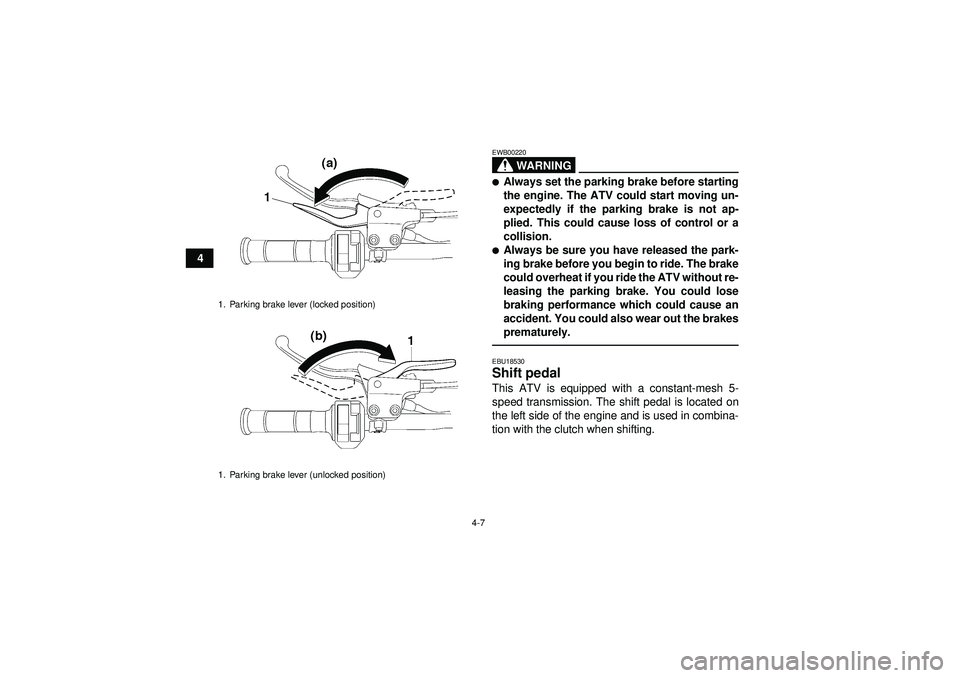
EWB00220�Always set the parking brake before starting
the engine. The ATV could start moving un-
expectedly if the parking brake is not ap-
plied. This could cause loss of control or a
collision.�Always be sure you have released the park-
ing brake before you begin to ride. The brake
could overheat if you ride the ATV without re-
leasing the parking brake. You could lose
braking performance which could cause an
accident. You could also wear out the brakes
prematurely.EBU18530Shift pedal This ATV is equipped with a constant-mesh 5-
speed transmission. The shift pedal is located on
the left side of the engine and is used in combina-
tion with the clutch when shifting.
1. Parking brake lever (locked position)
1. Parking brake lever (unlocked position)U1PD60E0.book Page 7 Monday, June 13, 2011 2:57 PM
Page 33 of 152
4-8
4
EBU18720Fuel tank cap Remove the fuel tank cap by turning it counter-
clockwise.
EBU18814Fuel Make sure there is sufficient gasoline in the tank.
WARNING
EWB02521Gasoline and gasoline vapors are extremely
flammable. To avoid fires and explosions and
to reduce the risk of injury when refueling, fol-
low these instructions.1. Before refueling, turn off the engine and besure that no one is sitting on the vehicle. Nev-
er refuel while smoking, or while in the vicinity
1. Shift pedal
1
1. Fuel tank cap
1
U1PD60E0.book Page 8 Monday, June 13, 2011 2:57 PM
Page 34 of 152

4-9
4of sparks, open flames, or other sources of ig-
nition such as the pilot lights of water heaters
and clothes dryers.
2. Do not overfill the fuel tank. When refueling, be sure to insert the pump nozzle into the fuel
tank filler hole. Stop filling when the fuel reach-
es the bottom of the filler tube. Because fuel
expands when it heats up, heat from the en-
gine or the sun can cause fuel to spill out of
the fuel tank.
3. Wipe up any spilled fuel immediately.NOTICE: Immediately wipe off spilled fuel
with a clean, dry, soft cloth, since fuel may
deteriorate painted surfaces or plastic
parts.
[ECB00981]
4. Turn the fuel tank cap fully clockwise to make sure it is securely closed.
WARNING
EWB02531Gasoline is poisonous and can cause injury or
death. Handle gasoline with care. Never siphon
gasoline by mouth. If you should swallow
some gasoline or inhale a lot of gasoline vapor,
or get some gasoline in your eyes, see your
1. Maximum fuel level
2. Fuel tank filler tube
Recommended fuel:PREMIUM UNLEADED GASOLINE ONLY
For Europe: PREMIUM UNLEADED GASO-
LINE ONLY with a research octane number
of 97 or higher
Fuel tank capacity: 10.0 L (2.64 US gal, 2.20 Imp.gal)
Fuel reserve amount: 1.9 L (0.50 US gal, 0.42 Imp.gal)
U1PD60E0.book Page 9 Monday, June 13, 2011 2:57 PM
Page 38 of 152
4-13
4
EBU18993Adjusting the front shock absorber as-
semblies The spring preload can be adjusted to suit the rid-
er’s weight and the riding conditions.
WARNING
EWB00400Always adjust the shock absorber assemblies
on the left and right side to the same setting.
Uneven adjustment can cause poor handling
and loss of stability, which could lead to an ac-
cident.
Adjust the spring preload as follows.
Turn the spring preload adjusting ring in direction
(a) to increase the spring preload and thereby
harden the suspension, and in direction (b) to de-
crease the spring preload and thereby soften the
suspension.
Align the appropriate notch in the adjusting ring
with the position indicator on the shock absorber.TIPA special wrench can be obtained at a Yamaha
dealer to make this adjustment.
1. Projection
2. Seat holder
1
2
1. Spring preload adjusting ring
2. Special wrench
3. Position indicator
1 2 3
4 5
(a)
(b) 1
2
3
U1PD60E0.book Page 13 Monday, June 13, 2011 2:57 PM
Page 42 of 152

4-17
48. Place the air filter case in the original position,
connect the air intake duct, and then tighten
the clamp screw at the carburetor side.
NOTICE: Make sure that the air intake duct
is properly connected to the carburetor,
and that the clamp screw is tightened se-
curely.
[ECB01170]
9. Install the bolts, install the hose joint, and then connect the hoses.
10. Install the seat.
WARNING
EWB00450This shock absorber assembly contains highly
pressurized nitrogen gas. If the shock absorb-
er assembly is damaged, it could explode
causing injury or property damage. Shock ab-
sorber cylinder damage could also result in
poor handling which could cause an accident.�Do not tamper with or attempt to open the
cylinder assembly.�Do not subject the shock absorber assembly
to an open flame or other high heat.
�Do not deform or damage the cylinder in any
way.�Do not dispose of a damaged or worn out
shock absorber assembly yourself. Take the
shock absorber assembly to a Yamaha deal-
er for any service.
Tightening torque: Locknut:44 Nm (4.4 m ·kgf, 32 ft· lbf)
U1PD60E0.book Page 17 Monday, June 13, 2011 2:57 PM
Page 43 of 152

5-1
5
EBU19201
PRE-OPERATION CHECKS
EBU19224Inspect your vehicle each time you use it to make sure the vehicle is in safe operating condition. Always
follow the inspection and maintenance procedures and schedules described in the Owner’s Manual.
WARNING
EWB00481Failure to inspect or maintain the vehicle properly increases the possibility of an accident or equip-
ment damage. Do not operate the vehicle if you find any problem. If a problem cannot be corrected
by the procedures provided in this manual, have the vehicle inspected by a Yamaha dealer.Before using this vehicle, check the following points:
ITEM ROUTINE PAGE
Fuel
Check fuel level in fuel tank, and add recommended fuel if neces-
sary.
Check fuel line for leakage. Correct if necessary. 4-8, 5-4
Engine oil
Check oil level in engine oil tank, and add recommended oil to spec-
ified level if necessary.
Check ATV for oil leakage. Correct if necessary. 5-4, 8-14
Coolant
Check coolant level in reservoir, and add recommended coolant to
specified level if necessary.
Check cooling system for leakage. Correct if necessary. 5-4, 8-20
U1PD60E0.book Page 1 Monday, June 13, 2011 2:57 PM
Page 47 of 152

5-5
5
EBU19761Throttle lever Check the operation of the throttle lever. It must
open smoothly and spring back to the idle position
when released. Have a Yamaha dealer correct if
necessary.EBU19770Drive chain Check the condition of the drive chain and check
the drive chain slack. Lubricate and adjust the
drive chain as necessary. (See page 8-41.)EBU19794Tires Check tire pressure regularly to make sure it is at
the recommended specifications. Also check for
wear and damage.
Tire pressure
Use the low-pressure tire gauge to check and ad-
just tire pressures when the tires are cold. Tire
pressures must be equal on both sides.
WARNING! Operation of this vehicle with im- proper tire pressure may cause severe injury
or death from loss of control or rollover. Tire
pressure below the minimum specified could also cause the tire to dislodge from the rim un-
der severe riding conditions.
[EWB02541]
Set tire
pressures to the following specifications:
The low-pressure tire gauge is included as stan-
dard equipment. Make two measurements of the
tire pressure and use the second reading. Dust or
dirt in the gauge could cause the first reading to be
incorrect. Recommended tire pressure:
Fron t25.0 kPa (0.250 kgf/cm ², 3.6 psi)
Rear 30.0 kPa (0.300 kgf/cm ², 4.4 psi)
Minimum tire pressure: Fron t22.0 kPa (0.220 kgf/cm ², 3.2 psi)
Rear 27.0 kPa (0.270 kgf/cm ², 4.0 psi)
Maximum tire seating pressure: Fron t250 kPa (2.5 kgf/cm² , 36 psi)
Rear 250 kPa (2.5 kgf/cm² , 36 psi)
U1PD60E0.book Page 5 Monday, June 13, 2011 2:57 PM