Page 24 of 96

When the key is turned to “ON”, the
speedometer needle will sweep once
across the speed range and then
return to zero in order to test the elec-
trical circuit.EAU11872
Tachometer
1. Tachometer
2. Tachometer red zone
The electric tachometer allows the
rider to monitor the engine speed and
keep it within the ideal power range.
When the key is turned to “ON”, the
tachometer needle will sweep once
across the r/min range and then
return to zero r/min in order to test the
electrical circuit.
ECA10031
Do not operate the engine in the
tachometer red zone.
Red zone: 10000 r/min and above
EAUS1681
Multi-function display
EWA12312
Be sure to stop the vehicle before
making any setting changes to the
multi-function display. Changing
settings while riding can distract
the operator and increase the risk
of an accident.
1. Clock/ambient temperature display
2. Coolant temperature meter
3. Fuel meter
4. Odometer/tripmeter/fuel reserve tripmeter
5. “SELECT” button
6. “RESET” button
WARNING
NOTICE
INSTRUMENT AND CONTROL FUNCTIONS
3-6
3
Page 25 of 96

1. V-belt replacement indicator “V-BELT”
2. Fuel level warning indicator “ ”
3. Coolant temperature warning indicator “ ”
4. Oil change indicator “OIL”
The multi-function display is equip-
ped with the following:
�a fuel meter
�a coolant temperature meter
�an odometer
�two tripmeters (which show the
distance traveled since they were
last set to zero)
�a fuel reserve tripmeter (which
shows the distance traveled sin-
ce the bottom segment of the
fuel meter and fuel level warning
indicator started flashing)
�a self-diagnosis device
�a clock
�an ambient temperature display
�an oil change indicator
�a V-belt replacement indicator
TIP
�Be sure to turn the key to “ON”
before using the “SELECT” and
“RESET” buttons.
�When the key is turned to “ON”,
all of the display segments of the
multi-function display will appear
and then disappear, in order to
test the electrical circuit.
Odometer and tripmeter modes
Pushing the “SELECT” button swit-
ches the display between the odome-
ter mode “Odo” and the tripmeter
modes “Trip” in the following order:
Odo/Trip (top) �Trip (bottom)/Trip
(top) �Odo/Trip (top)When approximately 2.0 L (0.53 US
gal, 0.44 Imp.gal) of fuel remains in
the fuel tank, the bottom segment of
the fuel meter and fuel level warning
indicator will start flashing, and the
display will automatically change to
the fuel reserve tripmeter mode “Trip
F” and start counting the distance tra-
veled from that point. In that case,
pushing the “SELECT” button swit-
ches the display between the various
tripmeter and odometer modes in the
following order:
Trip F/Trip (top) �Trip (bottom)/Trip
(top) �Odo/Trip (top) �Trip F/Trip
(top)
INSTRUMENT AND CONTROL FUNCTIONS
3-7
3
Page 51 of 96
PERIODIC MAINTENANCE AND ADJUSTMENT
6-3
6
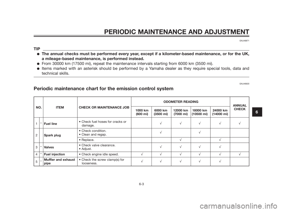
EAU46871
TIP
�The annual checks must be performed every year, except if a kilometer-based maintenance, or for the UK,
a mileage-based maintenance, is performed instead.
�From 30000 km (17500 mi), repeat the maintenance intervals starting from 6000 km (3500 mi).
�Items marked with an asterisk should be performed by a Yamaha dealer as they require special tools, data and
technical skills.
EAU46920
Periodic maintenance chart for the emission control system
ODOMETER READING
NO. ITEM CHECK OR MAINTENANCE JOBANNUAL
1000 km 6000 km 12000 km 18000 km 24000 kmCHECK
(600 mi) (3500 mi) (7000 mi) (10500 mi) (14000 mi)
1*Fuel line
damage.�3�3�3 �3�3
2Spark plug
�3�3
�3�3
3*Valves
�3�3�3 �3
4*Fuel injection�3�3 �3 �3 �3 �3
5*Muffler and exhaust
pipelooseness.�3�3 �3 �3 �3
Page 52 of 96
PERIODIC MAINTENANCE AND ADJUSTMENT
6-4
6
EAU17717
General maintenance and lubrication chart
ODOMETER READING
NO. ITEM CHECK OR MAINTENANCE JOBANNUAL
1000 km 6000 km 12000 km 18000 km 24000 kmCHECK
(600 mi) (3500 mi) (7000 mi) (10500 mi) (14000 mi)
1Air filter element�3�3
2V-belt case air filter
element�3�3�3 �3
3*Front brakevehicle for fluid leakage.�3�3 �3 �3 �3 �3
Whenever worn to the limit
4*Rear brakevehicle for fluid leakage.�3�3 �3 �3 �3 �3
Whenever worn to the limit
5*Brake hoses�3�3�3 �3�3 Every 4 years
6*Wheels�3�3�3 �3
damage.
7*Tires�3�3�3 �3�3
8*Wheel bearings
damage.�3�3�3 �3
Page 53 of 96
PERIODIC MAINTENANCE AND ADJUSTMENT
6-5
6
ODOMETER READING
NO. ITEM CHECK OR MAINTENANCE JOBANNUAL
1000 km 6000 km 12000 km 18000 km 24000 kmCHECK
(600 mi) (3500 mi) (7000 mi) (10500 mi) (14000 mi)
9*Steering bearingsfor roughness.�3�3 �3 �3 �3
based grease.Every 24000 km (14000 mi)
10 *Chassis fasteners
screws are properly tightened.�3�3�3 �3�3
11Front brake lever
pivot shaft�3�3�3 �3�3
12Rear brake lever
pivot shaft�3�3�3 �3�3
Sidestand,
13 �3�3�3 �3�3
centerstand
based grease.
14 *Sidestand switch�3�3 �3 �3 �3 �3
15 *Front fork
leakage.�3�3�3 �3
16 *Shock absorber
assembliesabsorbers for oil leakage.�3�3�3 �3
When the oil change indicator flashes [5000 km (3000 mi)
�3after the initial 1000 km (600 mi) and every 6000 km
17Engine oiland 6-10.)
(3500 mi) thereafter]
leakage.Every 3000 km (1800 mi)�3
18Engine oil filter
element�3�3 �3
Page 54 of 96
PERIODIC MAINTENANCE AND ADJUSTMENT
6-6
6
ODOMETER READING
NO. ITEM CHECK OR MAINTENANCE JOBANNUAL
1000 km 6000 km 12000 km 18000 km 24000 kmCHECK
(600 mi) (3500 mi) (7000 mi) (10500 mi) (14000 mi)
19 *Cooling systemfor coolant leakage.�3�3�3 �3�3
Every 3 years
20Final transmission �3�3 �3oil
�3�3 �3
21 *V-beltWhen the V-belt replacement indicator flashes
[every 18000 km (10500 mi)]
22 *Front and rear brake
switches�3�3 �3 �3 �3
�3
23Moving parts and
cables�3�3�3 �3
�3
Throttle grip housing
24 * if necessary.�3�3�3 �3�3
and cable
housing and cable.
25 *Lights, signals and
switches�3�3 �3 �3 �3 �3

 (3500 mi) (7000 mi) (10500 mi) (14000 mi)
9")
 (3500 mi) (7000 mi) (10500 mi) (14000 mi)
1")