2012 YAMAHA FZ1 S lock
[x] Cancel search: lockPage 36 of 106

INSTRUMENT AND CONTROL FUNCTIONS
3-21
3
EAU50850
Storage compartment The storage compartment is located
under the passenger seat. (See page
3-19.)
When storing the Owner’s Manual or
other documents in the storage com-
partment, be sure to wrap them in a
plastic bag so that they will not get wet.
When washing the vehicle, be careful
not to let any water enter the storage
compartment.
This storage compartment is designed
to hold an optional genuine Yamaha
CYCLELOK. (Other locks may not fit.) When placing a CYCLELOK in the stor-
age compartment, securely fasten it
with the straps. When the CYCLELOK is not in the storage compartment, be
sure to secure the straps to prevent los-
ing them.
WARNING
EWA10961
●
Do not exceed the load limit of 3
kg (7 lb) for the storage com-
partment.
●
Do not exceed the maximum
load of FZ1-S 190 kg (419 lb)
FZ1-SA 184 kg (406 lb) for the
vehicle.
EAU39671
Rear view mirrors The rear view mirrors of this vehicle can
be folded forward or backward for park-
ing in narrow spaces. Fold the mirrors
back to their original position before
riding.
WARNING
EWA14371
Be sure to fold the rear view mirrors
back to their original position before
riding.
1. Storage compartment
1
1. CYCLELOK bar (optional)
2. Strap
3. Yamaha CYCLELOK (optional)
1. Riding position
2. Parking position
1
1
2
2
22
U1CAE1E0.book Page 21 Tuesday, September 13, 2011 5:02 PM
Page 74 of 106
PERIODIC MAINTENANCE AND ADJUSTMENT
6-24
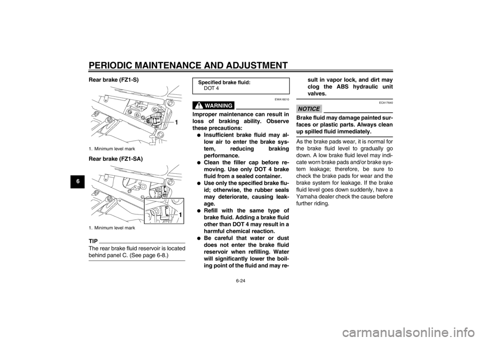
6Rear brake (FZ1-S)
Rear brake (FZ1-SA)
TIPThe rear brake fluid reservoir is located
behind panel C. (See page 6-8.)
WARNING
EWA16010
Improper maintenance can result in
loss of braking ability. Observe
these precautions:●
Insufficient brake fluid may al-
low air to enter the brake sys-
tem, reducing braking
performance.
●
Clean the filler cap before re-
moving. Use only DOT 4 brake
fluid from a sealed container.
●
Use only the specified brake flu-
id; otherwise, the rubber seals
may deteriorate, causing leak-
age.
●
Refill with the same type of
brake fluid. Adding a brake fluid
other than DOT 4 may result in a
harmful chemical reaction.
●
Be careful that water or dust
does not enter the brake fluid
reservoir when refilling. Water
will significantly lower the boil-
ing point of the fluid and may re- sult in vapor lock, and dirt may
clog the ABS hydraulic unit
valves.
NOTICE
ECA17640
Brake fluid may damage painted sur-
faces or plastic parts. Always clean
up spilled fluid immediately.As the brake pads wear, it is normal for
the brake fluid level to gradually go
down. A low brake fluid level may indi-
cate worn brake pads and/or brake sys-
tem leakage; therefore, be sure to
check the brake pads for wear and the
brake system for leakage. If the brake
fluid level goes down suddenly, have a
Yamaha dealer check the cause before further riding.
1. Minimum level mark
1. Minimum level mark
Specified brake fluid: DOT 4
U1CAE1E0.book Page 24 Tuesday, September 13, 2011 5:02 PM
Page 75 of 106
PERIODIC MAINTENANCE AND ADJUSTMENT
6-25
6
EAU22731
Changing the brake fluid Have a Yamaha dealer change the
brake fluid at the intervals specified in
the TIP after the periodic maintenance
and lubrication chart. In addition, have
the oil seals of the master cylinders and
calipers as well as the brake hoses re-
placed at the intervals listed below or
whenever they are damaged or leak-
ing.●
Oil seals: Replace every two
years.
●
Brake hoses: Replace every four
years.
EAU22760
Drive chain slack The drive chain slack should be
checked before each ride and adjusted
if necessary.
EAU22794
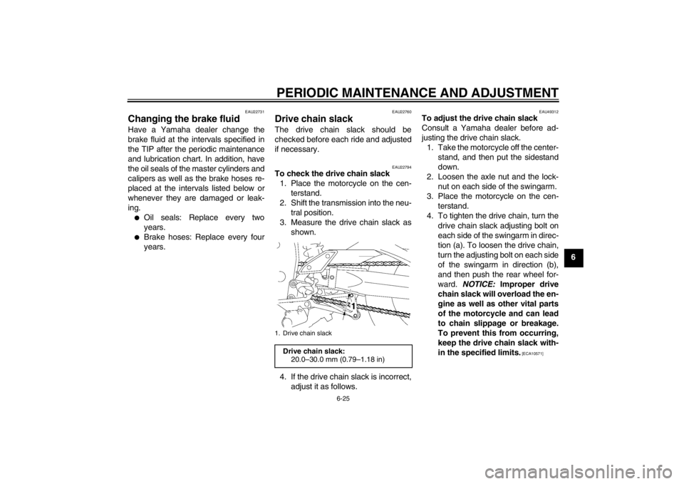
To check the drive chain slack1. Place the motorcycle on the cen- terstand.
2. Shift the transmission into the neu- tral position.
3. Measure the drive chain slack as shown.
4. If the drive chain slack is incorrect, adjust it as follows.
EAU49312
To adjust the drive chain slack
Consult a Yamaha dealer before ad-
justing the drive chain slack.1. Take the motorcycle off the center- stand, and then put the sidestand
down.
2. Loosen the axle nut and the lock- nut on each side of the swingarm.
3. Place the motorcycle on the cen- terstand.
4. To tighten the drive chain, turn the drive chain slack adjusting bolt on
each side of the swingarm in direc-
tion (a). To loosen the drive chain,
turn the adjusting bolt on each side
of the swingarm in direction (b),
and then push the rear wheel for-
ward. NOTICE: Improper drive
chain slack will overload the en-
gine as well as other vital parts
of the motorcycle and can lead
to chain slippage or breakage.
To prevent this from occurring,
keep the drive chain slack with-
in the specified limits.
[ECA10571]
1. Drive chain slack
Drive chain slack: 20.0–30.0 mm (0.79–1.18 in)
U1CAE1E0.book Page 25 Tuesday, September 13, 2011 5:02 PM
Page 76 of 106

PERIODIC MAINTENANCE AND ADJUSTMENT
6-26
6
TIPUsing the alignment marks on each
side of the swingarm, make sure that
both drive chain pullers are in the same
position for proper wheel alignment.5. Take the motorcycle off the center-stand, and then put the sidestand
down.
6. Tighten the axle nut, then the lock- nuts to the specified torques. 7. Make sure that the drive chain pull-
ers are in the same position, the
drive chain slack is correct, and
the drive chain moves smoothly.
EAU23025
Cleaning and lubricating the
drive chain The drive chain must be cleaned and
lubricated at the intervals specified in
the periodic maintenance and lubrica-
tion chart, otherwise it will quickly wear
out, especially when riding in dusty or
wet areas. Service the drive chain as
follows.NOTICE
ECA10583
The drive chain must be lubricated
after washing the motorcycle, riding
in the rain or riding in wet areas.1. Clean the drive chain with kero-sene and a small soft brush.
NOTICE: To prevent damaging
the O-rings, do not clean the
drive chain with steam cleaners,
high-pressure washers or inap-
propriate solvents.
[ECA11121]
2. Wipe the drive chain dry.
3. Thoroughly lubricate the drive chain with a special O-ring chain
lubricant. NOTICE: Do not use
engine oil or any other lubri-
cants for the drive chain, as they
1. Axle nut
2. Drive chain slack adjusting bolt
3. Locknut
4. Drive chain puller
5. Alignment marks
1
4
5
23
(a)
(b)
Tightening torques: Axle nut:
150 Nm (15 m·kgf, 108 ft·lbf)
Locknut:
16 Nm (1.6 m·kgf, 12 ft·lbf)
U1CAE1E0.book Page 26 Tuesday, September 13, 2011 5:02 PM
Page 83 of 106
PERIODIC MAINTENANCE AND ADJUSTMENT
6-33
6
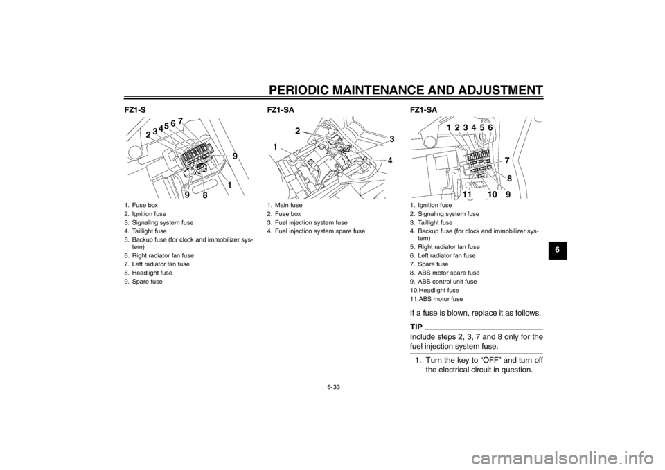
FZ1-S FZ1-SA FZ1-SA
If a fuse is blown, replace it as follows.
TIPInclude steps 2, 3, 7 and 8 only for the
fuel injection system fuse.1. Turn the key to “OFF” and turn offthe electrical circuit in question.
1. Fuse box
2. Ignition fuse
3. Signaling system fuse
4. Taillight fuse
5. Backup fuse (for clock and immobilizer sys-tem)
6. Right radiator fan fuse
7. Left radiator fan fuse
8. Headlight fuse
9. Spare fuse
1. Main fuse
2. Fuse box
3. Fuel injection system fuse
4. Fuel injection system spare fuse
1. Ignition fuse
2. Signaling system fuse
3. Taillight fuse
4. Backup fuse (for clock and immobilizer sys- tem)
5. Right radiator fan fuse
6. Left radiator fan fuse
7. Spare fuse
8. ABS motor spare fuse
9. ABS control unit fuse
10.Headlight fuse
11.ABS motor fuse
U1CAE1E0.book Page 33 Tuesday, September 13, 2011 5:02 PM
Page 86 of 106
PERIODIC MAINTENANCE AND ADJUSTMENT
6-36
6
EAU24115
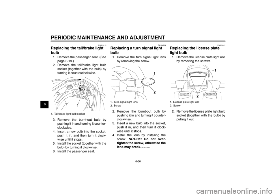
Replacing the tail/brake light
bulb 1. Remove the passenger seat. (Seepage 3-19.)
2. Remove the tail/brake light bulb socket (together with the bulb) by
turning it counterclockwise.
3. Remove the burnt-out bulb by pushing it in and turning it counter-
clockwise.
4. Insert a new bulb into the socket, push it in, and then turn it clock-
wise until it stops.
5. Install the socket (together with the bulb) by turning it clockwise.
6. Install the passenger seat.
EAU24204
Replacing a turn signal light
bulb 1. Remove the turn signal light lens by removing the screw.
2. Remove the burnt-out bulb by pushing it in and turning it counter-
clockwise.
3. Insert a new bulb into the socket, push it in, and then turn it clock-
wise until it stops.
4. Install the lens by installing the screw. NOTICE: Do not over-
tighten the screw, otherwise the
lens may break.
[ECA11191] EAU24313
Replacing the license plate
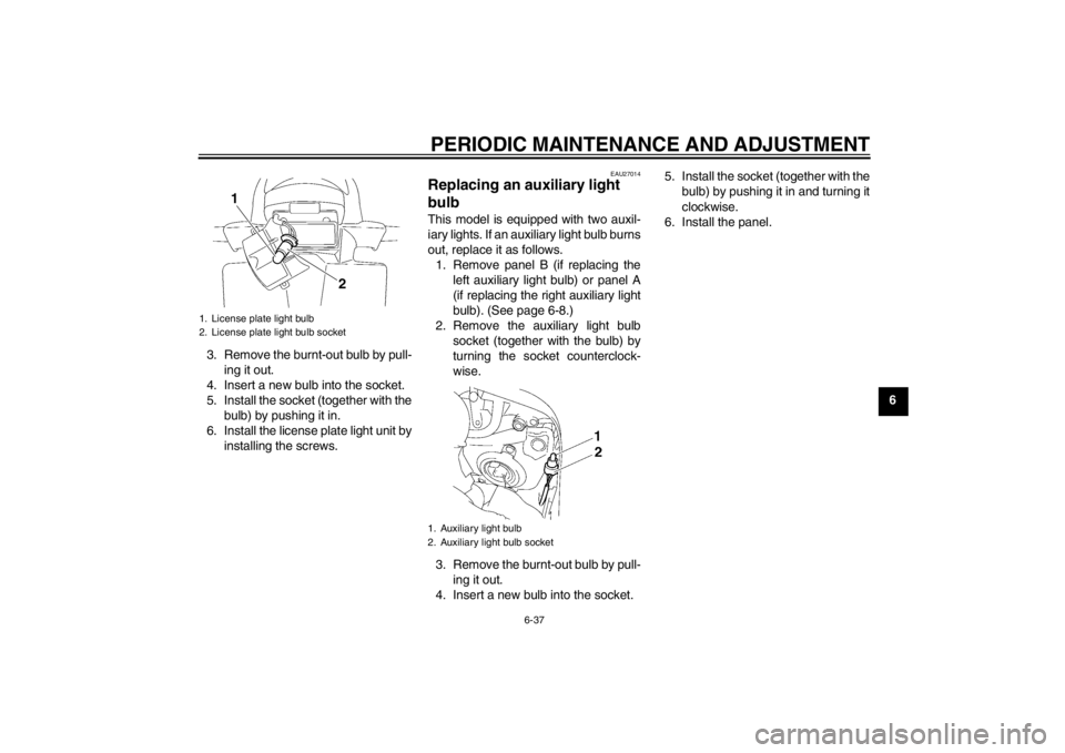
light bulb 1. Remove the license plate light unit
by removing the screws.
2. Remove the license plate light bulb socket (together with the bulb) by
pulling it out.
1. Tail/brake light bulb socket
1. Turn signal light lens
2. Screw
1. License plate light unit
2. Screw
U1CAE1E0.book Page 36 Tuesday, September 13, 2011 5:02 PM
Page 87 of 106
PERIODIC MAINTENANCE AND ADJUSTMENT
6-37
6
3. Remove the burnt-out bulb by pull-
ing it out.
4. Insert a new bulb into the socket.
5. Install the socket (together with the bulb) by pushing it in.
6. Install the license plate light unit by installing the screws.
EAU27014
Replacing an auxiliary light
bulb This model is equipped with two auxil-
iary lights. If an auxiliary light bulb burns
out, replace it as follows.1. Remove panel B (if replacing the left auxiliary light bulb) or panel A
(if replacing the right auxiliary light
bulb). (See page 6-8.)
2. Remove the auxiliary light bulb socket (together with the bulb) by
turning the socket counterclock-
wise.
3. Remove the burnt-out bulb by pull- ing it out.
4. Insert a new bulb into the socket. 5. Install the socket (together with the
bulb) by pushing it in and turning it
clockwise.
6. Install the panel.
1. License plate light bulb
2. License plate light bulb socket
1
2
1. Auxiliary light bulb
2. Auxiliary light bulb socket
U1CAE1E0.book Page 37 Tuesday, September 13, 2011 5:02 PM
Page 89 of 106
PERIODIC MAINTENANCE AND ADJUSTMENT
6-39
6
4. Install the brake hose holder on
each side by installing the bolt and
nut.
5. Take the vehicle off the center- stand so that the front wheel is on
the ground, and then put the side-
stand down.
6. Tighten the wheel axle, the front wheel axle pinch bolt, and the
brake caliper bolts to the specified
torques.
7. Push down hard on the handlebar several times to check for proper
fork operation.
EAU44801
Rear wheel (for non-ABS mod-
els)
WARNING
EWA14840
For the ABS model, have a Yamaha
dealer remove and install the wheel.
EAU40022
To remove the rear wheel
WARNING
EWA10821
To avoid injury, securely support the
vehicle so there is no danger of it
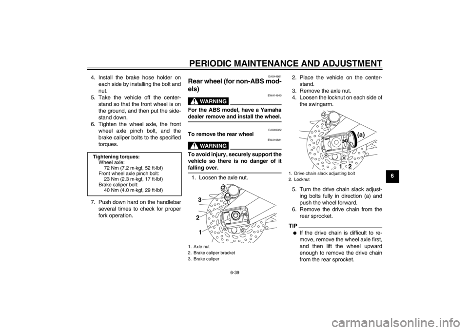
falling over.1. Loosen the axle nut. 2. Place the vehicle on the center-
stand.
3. Remove the axle nut.
4. Loosen the locknut on each side of the swingarm.
5. Turn the drive chain slack adjust- ing bolts fully in direction (a) and
push the wheel forward.
6. Remove the drive chain from the rear sprocket.
TIP●
If the drive chain is difficult to re-
move, remove the wheel axle first,
and then lift the wheel upward
enough to remove the drive chain
from the rear sprocket.
Tightening torques:Wheel axle:72 Nm (7.2 m·kgf, 52 ft·lbf)
Front wheel axle pinch bolt:
23 Nm (2.3 m·kgf, 17 ft·lbf)
Brake caliper bolt: 40 Nm (4.0 m·kgf, 29 ft·lbf)
1. Axle nut
2. Brake caliper bracket
3. Brake caliper
321
1. Drive chain slack adjusting bolt
2. Locknut
(a)
1
2
U1CAE1E0.book Page 39 Tuesday, September 13, 2011 5:02 PM