2012 YAMAHA FZ1 S brake fluid
[x] Cancel search: brake fluidPage 74 of 106

PERIODIC MAINTENANCE AND ADJUSTMENT
6-24
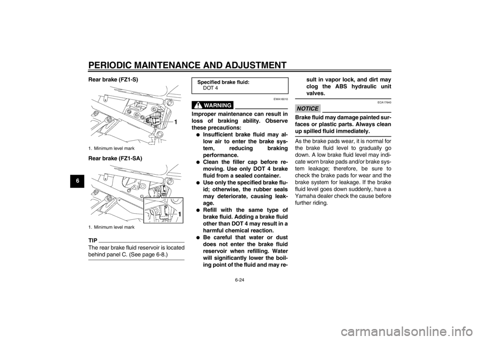
6Rear brake (FZ1-S)
Rear brake (FZ1-SA)
TIPThe rear brake fluid reservoir is located
behind panel C. (See page 6-8.)
WARNING
EWA16010
Improper maintenance can result in
loss of braking ability. Observe
these precautions:●
Insufficient brake fluid may al-
low air to enter the brake sys-
tem, reducing braking
performance.
●
Clean the filler cap before re-
moving. Use only DOT 4 brake
fluid from a sealed container.
●
Use only the specified brake flu-
id; otherwise, the rubber seals
may deteriorate, causing leak-
age.
●
Refill with the same type of
brake fluid. Adding a brake fluid
other than DOT 4 may result in a
harmful chemical reaction.
●
Be careful that water or dust
does not enter the brake fluid
reservoir when refilling. Water
will significantly lower the boil-
ing point of the fluid and may re- sult in vapor lock, and dirt may
clog the ABS hydraulic unit
valves.
NOTICE
ECA17640
Brake fluid may damage painted sur-
faces or plastic parts. Always clean
up spilled fluid immediately.As the brake pads wear, it is normal for
the brake fluid level to gradually go
down. A low brake fluid level may indi-
cate worn brake pads and/or brake sys-
tem leakage; therefore, be sure to
check the brake pads for wear and the
brake system for leakage. If the brake
fluid level goes down suddenly, have a
Yamaha dealer check the cause before further riding.
1. Minimum level mark
1. Minimum level mark
Specified brake fluid: DOT 4
U1CAE1E0.book Page 24 Tuesday, September 13, 2011 5:02 PM
Page 75 of 106

PERIODIC MAINTENANCE AND ADJUSTMENT
6-25
6
EAU22731
Changing the brake fluid Have a Yamaha dealer change the
brake fluid at the intervals specified in
the TIP after the periodic maintenance
and lubrication chart. In addition, have
the oil seals of the master cylinders and
calipers as well as the brake hoses re-
placed at the intervals listed below or
whenever they are damaged or leak-
ing.●
Oil seals: Replace every two
years.
●
Brake hoses: Replace every four
years.
EAU22760
Drive chain slack The drive chain slack should be
checked before each ride and adjusted
if necessary.
EAU22794
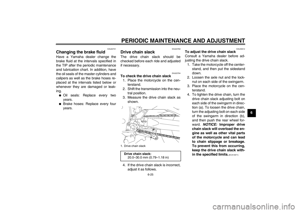
To check the drive chain slack1. Place the motorcycle on the cen- terstand.
2. Shift the transmission into the neu- tral position.
3. Measure the drive chain slack as shown.
4. If the drive chain slack is incorrect, adjust it as follows.
EAU49312
To adjust the drive chain slack
Consult a Yamaha dealer before ad-
justing the drive chain slack.1. Take the motorcycle off the center- stand, and then put the sidestand
down.
2. Loosen the axle nut and the lock- nut on each side of the swingarm.
3. Place the motorcycle on the cen- terstand.
4. To tighten the drive chain, turn the drive chain slack adjusting bolt on
each side of the swingarm in direc-
tion (a). To loosen the drive chain,
turn the adjusting bolt on each side
of the swingarm in direction (b),
and then push the rear wheel for-
ward. NOTICE: Improper drive
chain slack will overload the en-
gine as well as other vital parts
of the motorcycle and can lead
to chain slippage or breakage.
To prevent this from occurring,
keep the drive chain slack with-
in the specified limits.
[ECA10571]
1. Drive chain slack
Drive chain slack: 20.0–30.0 mm (0.79–1.18 in)
U1CAE1E0.book Page 25 Tuesday, September 13, 2011 5:02 PM
Page 99 of 106

SPECIFICATIONS
8-2
8
2nd:2.063 (33/16)
3rd: 1.762 (37/21)
4th:
1.522 (35/23)
5th: 1.350 (27/20)
6th: 1.208 (29/24)
Chassis:Frame type:Diamond
Caster angle: 25.00 °
Trail:
109 mm (4.3 in)Front tire:Type:Tubeless
Size:
120/70 ZR17M/C (58W)
Manufacturer/model: DUNLOP/D221FARear tire:Type:
Tubeless
Size: 190/50 ZR17M/C (73W)
Manufacturer/model: DUNLOP/D221G
Loading:Maximum load: FZ1-S 190 kg (419 lb)
FZ1-SA 184 kg (406 lb)
(Total weight of rider, passenger, cargo and
accessories)Tire air pressure (measured on cold
tires):Loading condition:0–90 kg (0–198 lb)
Front:
250 kPa (2.50 kgf/cm², 36 psi)
Rear: 290 kPa (2.90 kgf/cm², 42 psi)
Loading condition: FZ1-S 90–190 kg (198–419 lb)
FZ1-SA 90–184 kg (198–406 lb)
Front:250 kPa (2.50 kgf/cm², 36 psi)
Rear:
290 kPa (2.90 kgf/cm², 42 psi)
High-speed riding: Front:
250 kPa (2.50 kgf/cm², 36 psi)
Rear: 290 kPa (2.90 kgf/cm², 42 psi)Front wheel:Wheel type:
Cast wheel
Rim size: 17M/C x MT3.50Rear wheel:Wheel type:
Cast wheel Rim size:
17M/C x MT6.00
Front brake:Type:
Dual disc brake
Operation: Right hand operation
Specified brake fluid: DOT 4Rear brake:Type:Single disc brake
Operation: Right foot operation
Specified brake fluid:
DOT 4Front suspension:Type:Telescopic fork
Spring/shock absorber type:
Coil spring/oil damper
Wheel travel: 130.0 mm (5.12 in)Rear suspension:Type:
Swingarm (link suspension)
Spring/shock absorber type: Coil spring/gas-oil damper
Wheel travel: 130.0 mm (5.12 in)Electrical system:Ignition system:TCI
U1CAE1E0.book Page 2 Tuesday, September 13, 2011 5:02 PM
Page 102 of 106

INDEXAABS (for ABS models) .......................... 3-15
ABS warning light (for ABS models) ....... 3-7
Air filter element, replacing ................... 6-14
Anti-theft alarm (optional)...................... 3-12
Auxiliary light bulb, replacing ................ 6-37BBattery................................................... 6-31
Brake and clutch levers, checking and lubricating ..................... 6-28
Brake and shift pedals, checking and lubricating ..................... 6-28
Brake fluid, changing ............................ 6-25
Brake fluid level, checking .................... 6-23
Brake lever ............................................ 3-15
Brake lever free play, checking ............. 6-21
Brake light switches (for ABS models) ................................ 6-22
Brake light switches (for non-ABS models) ......................... 6-22
Brake pedal ........................................... 3-15CCables, checking and lubricating .......... 6-27
Care ........................................................ 7-1
Catalytic converters .............................. 3-19
Centerstand and sidestand,
checking and lubricating ..................... 6-29
Clutch lever ........................................... 3-14
Clutch lever free play, adjusting ............ 6-21
Coolant.................................................. 6-13
Coolant temperature warning light .......... 3-4DDimmer switch ...................................... 3-13
Drive chain, cleaning and lubricating .... 6-26 Drive chain slack .................................. 6-25
EEngine break-in ...................................... 5-3
Engine idling speed .............................. 6-17
Engine oil and oil filter cartridge ........... 6-10
Engine stop switch................................ 3-13
Engine trouble warning light ................... 3-7
EXUP system ....................................... 3-26FFront and rear brake pads, checking .... 6-23
Front fork, adjusting .............................. 3-22
Front fork, checking .............................. 6-30
Fuel....................................................... 3-17
Fuel consumption, tips for reducing........ 5-3
Fuel tank breather hose and
overflow hose ..................................... 3-18
Fuel tank cap ........................................ 3-16
Fuses, replacing ................................... 6-32HHandlebar switches .............................. 3-13
Hazard switch ....................................... 3-14
Headlight bulb, replacing ...................... 6-35
High beam indicator light ........................ 3-4
Horn switch ........................................... 3-13IIdentification numbers ............................ 9-1
Ignition circuit cut-off system ................ 3-27
Immobilizer system ................................. 3-1
Immobilizer system indicator light........... 3-7
Indicator lights and warning lights .......... 3-4LLicense plate light bulb, replacing ........ 6-36
Luggage strap holders .......................... 3-25
MMain switch/steering lock ........................ 3-2
Maintenance and lubrication, periodic..... 6-4
Maintenance, emission control system ... 6-3
Matte color, caution ................................. 7-1
Model label .............................................. 9-1
Multi-function meter unit .......................... 3-8NNeutral indicator light .............................. 3-4OOil level warning light .............................. 3-4PPanels, removing and installing .............. 6-8
Parking .................................................... 5-4
Part locations .......................................... 2-1
Pass switch ........................................... 3-13RRear view mirrors .................................. 3-21SSafety information ................................... 1-1
Seats ..................................................... 3-19
Shifting .................................................... 5-2
Shift pedal ............................................. 3-14
Shock absorber assembly, adjusting .... 3-24
Sidestand .............................................. 3-26
Spark plugs, checking ............................. 6-9
Specifications .......................................... 8-1
Starting the engine .................................. 5-1
Start switch............................................ 3-13
Steering, checking................................. 6-30
Storage.................................................... 7-3
Storage compartment............................ 3-21TTail/brake light bulb, replacing .............. 6-36
U1CAE1E0.book Page 1 Tuesday, September 13, 2011 5:02 PM