2012 YAMAHA FZ1-N torque
[x] Cancel search: torquePage 52 of 106
PERIODIC MAINTENANCE AND ADJUSTMENT
6-2
6
EAU17542
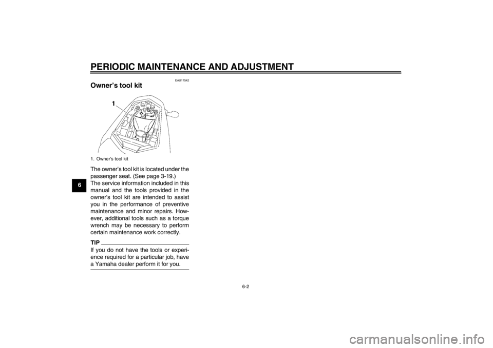
Owner’s tool kit The owner’s tool kit is located under the
passenger seat. (See page 3-19.)
The service information included in this
manual and the tools provided in the
owner’s tool kit are intended to assist
you in the performance of preventive
maintenance and minor repairs. How-
ever, additional tools such as a torque
wrench may be necessary to perform
certain maintenance work correctly.TIPIf you do not have the tools or experi-
ence required for a particular job, have
a Yamaha dealer perform it for you.1. Owner’s tool kitU1ECE1E0.book Page 2 Monday, August 8, 2011 11:52 AM
Page 59 of 106

PERIODIC MAINTENANCE AND ADJUSTMENT
6-9
6
FZ1-N
FZ1-NA
EAU19652
Checking the spark plugs The spark plugs are important engine
components, which should be checked
periodically, preferably by a Yamaha
dealer. Since heat and deposits will
cause any spark plug to slowly erode,
they should be removed and checked
in accordance with the periodic mainte-
nance and lubrication chart. In addition,
the condition of the spark plugs can re-
veal the condition of the engine.
The porcelain insulator around the cen-
ter electrode of each spark plug should
be a medium-to-light tan (the ideal color
when the vehicle is ridden normally),
and all spark plugs installed in the en-
gine should have the same color. If any
spark plug shows a distinctly different
color, the engine could be operating im-
properly. Do not attempt to diagnose
such problems yourself. Instead, have
a Yamaha dealer check the vehicle.
If a spark plug shows signs of electrode
erosion and excessive carbon or other
deposits, it should be replaced. Before installing a spark plug, the spark
plug gap should be measured with a
wire thickness gauge and, if necessary,
adjusted to specification.
Clean the surface of the spark plug
gasket and its mating surface, and then
wipe off any grime from the spark plug
threads.
Specified spark plug:
NGK/CR9E
1. Spark plug gap
Spark plug gap:0.7–0.8 mm (0.028–0.031 in)
Tightening torque: Spark plug: 13 Nm (1.3 m·kgf, 9.4 ft·lbf)
U1ECE1E0.book Page 9 Monday, August 8, 2011 11:52 AM
Page 60 of 106

PERIODIC MAINTENANCE AND ADJUSTMENT
6-10
6
TIPIf a torque wrench is not available when
installing a spark plug, a good estimate
of the correct torque is 1/4–1/2 turn
past finger tight. However, the spark
plug should be tightened to the speci-
fied torque as soon as possible.NOTICE
ECA10840
Do not use any tools to remove or in-
stall the spark plug cap, otherwise
the ignition coil coupler may get
damaged. The spark plug cap may
be difficult to remove because the
rubber seal on the end of the cap fits
tightly. To remove the spark plug
cap, simply twist it back and forth
while pulling it out; to install it, twist
it back and forth while pushing it in.
EAU49791
Engine oil and oil filter car-
tridge The engine oil level should be checked
before each ride. In addition, the oil
must be changed and the oil filter car-
tridge replaced at the intervals speci-
fied in the periodic maintenance and
lubrication chart.
To check the engine oil level1. Place the vehicle on a level sur- face and hold it in an upright posi-
tion. A slight tilt to the side can
result in a false reading.
2. Start the engine, warm it up for several minutes, and then turn it
off.
3. Wait a few minutes until the oil set- tles, and then check the oil level
through the check window located
at the bottom-right side of the
crankcase.TIPThe engine oil should be between the
minimum and maximum level marks.
FZ1-N
FZ1-NA1. Engine oil filler cap
2. Engine oil level check window
3. Maximum level mark
4. Minimum level mark
1. Engine oil filler cap
2. Engine oil level check window
3. Maximum level mark
4. Minimum level mark
34
12
U1ECE1E0.book Page 10 Monday, August 8, 2011 11:52 AM
Page 61 of 106
PERIODIC MAINTENANCE AND ADJUSTMENT
6-11
6
4. If the engine oil is below the mini-
mum level mark, add sufficient oil
of the recommended type to raise
it to the correct level.
To change the engine oil (with or
without oil filter cartridge replace-
ment) 1. Place the vehicle on a level sur- face.
2. Remove cowling A (for ABS mod- els only). (See page 6-8.)
3. Start the engine, warm it up for several minutes, and then turn it
off.
4. Place an oil pan under the engine to collect the used oil.
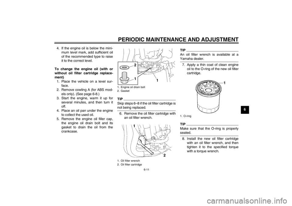
5. Remove the engine oil filler cap, the engine oil drain bolt and its
gasket to drain the oil from the
crankcase.
TIPSkip steps 6–8 if the oil filter cartridge is
not being replaced.6. Remove the oil filter cartridge withan oil filter wrench.
TIPAn oil filter wrench is available at a
Yamaha dealer.7. Apply a thin coat of clean engineoil to the O-ring of the new oil filter
cartridge.TIPMake sure that the O-ring is properly
seated.8. Install the new oil filter cartridgewith an oil filter wrench, and then
tighten it to the specified torque
with a torque wrench.
1. Engine oil drain bolt
2. Gasket
1. Oil filter wrench
2. Oil filter cartridge
1
1
2
1. O-ring
U1ECE1E0.book Page 11 Monday, August 8, 2011 11:52 AM
Page 62 of 106

PERIODIC MAINTENANCE AND ADJUSTMENT
6-12
69. Install the engine oil drain bolt and
its new gasket, and then tighten
the bolt to the specified torque.
10. Refill with the specified amount of the recommended engine oil, and
then install and tighten the oil filler
cap.
TIPBe sure to wipe off spilled oil on any
parts after the engine and exhaust sys-
tem have cooled down.NOTICE
ECA11620
●
In order to prevent clutch slip-
page (since the engine oil also
lubricates the clutch), do not
mix any chemical additives. Do
not use oils with a diesel speci-
fication of “CD” or oils of a high-
er quality than specified. In
addition, do not use oils labeled
“ENERGY CONSERVING II” or
higher.
●
Make sure that no foreign mate-
rial enters the crankcase.
11. Start the engine, and then let it idlefor several minutes while checking
it for oil leakage. If oil is leaking, im-
mediately turn the engine off and
check for the cause.TIPAfter the engine is started, the engine
oil level warning light should go off if the
oil level is sufficient.NOTICE
ECA10401
If the oil level warning light flickers
or remains on even if the oil level is
correct, immediately turn the engine
off and have a Yamaha dealer check
the vehicle.12. Turn the engine off, wait a few min-utes until the oil settles, and then
check the oil level and correct it if
necessary.
13. Install the cowling (for ABS models only).
1. Torque wrenchTightening torque:Oil filter cartridge:17 Nm (1.7 m·kgf, 12 ft·lbf)
Tightening torque: Engine oil drain bolt:
43 Nm (4.3 m·kgf, 31 ft·lbf)
Recommended engine oil:See page 8-1.
Oil quantity: Without oil filter cartridge replace-
ment:2.90 L (3.07 US qt, 2.55 Imp.qt)
With oil filter cartridge replacement:
3.10 L (3.28 US qt, 2.73 Imp.qt)
U1ECE1E0.book Page 12 Monday, August 8, 2011 11:52 AM
Page 75 of 106
PERIODIC MAINTENANCE AND ADJUSTMENT
6-25
6
EAU22760
Drive chain slack The drive chain slack should be
checked before each ride and adjusted
if necessary.
EAU22774
To check the drive chain slack1. Place the motorcycle on the side- stand.TIPWhen checking and adjusting the drive
chain slack, there should be no weight
on the motorcycle.2. Shift the transmission into the neu- tral position.
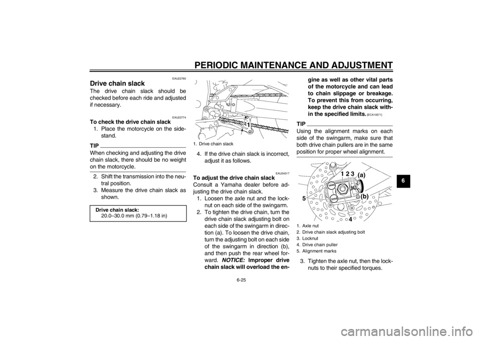
3. Measure the drive chain slack as shown. 4. If the drive chain slack is incorrect,
adjust it as follows.
EAU34317
To adjust the drive chain slack
Consult a Yamaha dealer before ad-
justing the drive chain slack.1. Loosen the axle nut and the lock- nut on each side of the swingarm.
2. To tighten the drive chain, turn the drive chain slack adjusting bolt on
each side of the swingarm in direc-
tion (a). To loosen the drive chain,
turn the adjusting bolt on each side
of the swingarm in direction (b),
and then push the rear wheel for-
ward. NOTICE: Improper drive
chain slack will overload the en- gine as well as other vital parts
of the motorcycle and can lead
to chain slippage or breakage.
To prevent this from occurring,
keep the drive chain slack with-
in the specified limits.
[ECA10571]
TIPUsing the alignment marks on each
side of the swingarm, make sure that
both drive chain pullers are in the same
position for proper wheel alignment.3. Tighten the axle nut, then the lock-
nuts to their specified torques.
Drive chain slack:20.0–30.0 mm (0.79–1.18 in)
1. Drive chain slack
1. Axle nut
2. Drive chain slack adjusting bolt
3. Locknut
4. Drive chain puller
5. Alignment marks
U1ECE1E0.book Page 25 Monday, August 8, 2011 11:52 AM
Page 76 of 106
PERIODIC MAINTENANCE AND ADJUSTMENT
6-26
64. Make sure that the drive chain pull-
ers are in the same position, the
drive chain slack is correct, and
the drive chain moves smoothly.
EAU23025
Cleaning and lubricating the
drive chain The drive chain must be cleaned and
lubricated at the intervals specified in
the periodic maintenance and lubrica-
tion chart, otherwise it will quickly wear
out, especially when riding in dusty or
wet areas. Service the drive chain as
follows.NOTICE
ECA10583
The drive chain must be lubricated
after washing the motorcycle, riding
in the rain or riding in wet areas.1. Clean the drive chain with kero-sene and a small soft brush.
NOTICE: To prevent damaging
the O-rings, do not clean the
drive chain with steam cleaners,
high-pressure washers or inap-
propriate solvents.
[ECA11121]
2. Wipe the drive chain dry.
3. Thoroughly lubricate the drive chain with a special O-ring chain
lubricant. NOTICE: Do not use
engine oil or any other lubri-
cants for the drive chain, as they may contain substances that
could damage the O-rings.
[ECA11111]
Tightening torques:
Axle nut:
150 Nm (15 m·kgf, 108 ft·lbf)
Locknut:
16 Nm (1.6 m·kgf, 12 ft·lbf)
U1ECE1E0.book Page 26 Monday, August 8, 2011 11:52 AM
Page 89 of 106
PERIODIC MAINTENANCE AND ADJUSTMENT
6-39
6
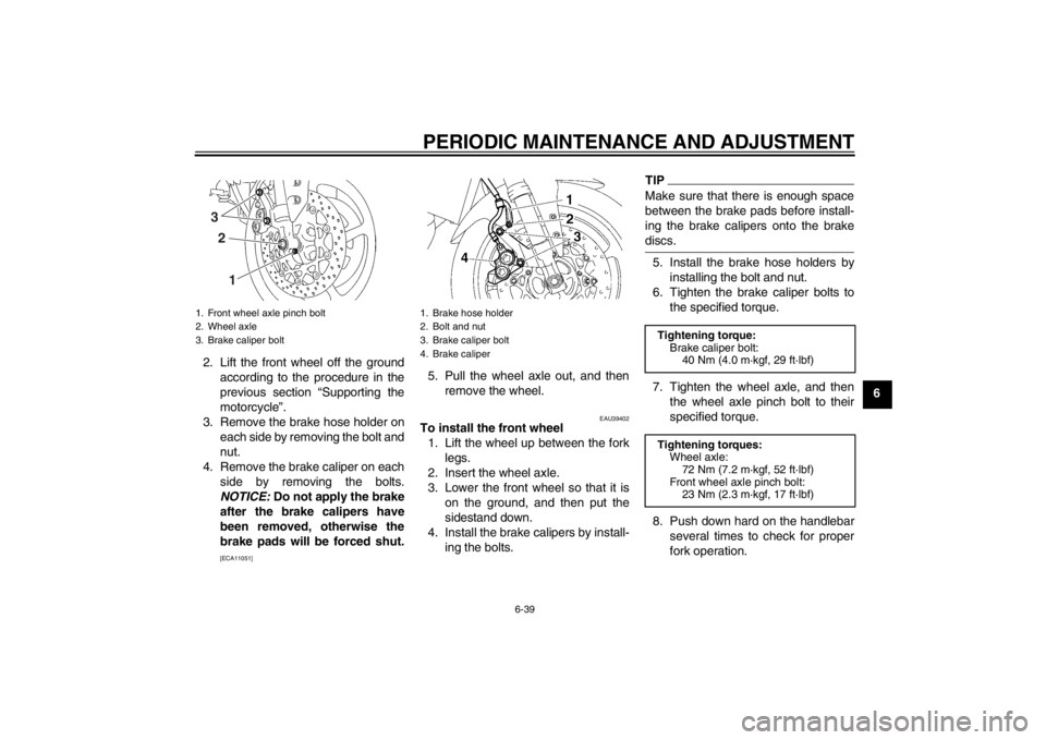
2. Lift the front wheel off the ground
according to the procedure in the
previous section “Supporting the
motorcycle”.
3. Remove the brake hose holder on each side by removing the bolt and
nut.
4. Remove the brake caliper on each side by removing the bolts.
NOTICE: Do not apply the brake
after the brake calipers have
been removed, otherwise the
brake pads will be forced shut.
[ECA11051]
5. Pull the wheel axle out, and then remove the wheel.
EAU39402
To install the front wheel1. Lift the wheel up between the fork legs.
2. Insert the wheel axle.
3. Lower the front wheel so that it is on the ground, and then put the
sidestand down.
4. Install the brake calipers by install- ing the bolts.
TIPMake sure that there is enough space
between the brake pads before install-
ing the brake calipers onto the brake
discs.5. Install the brake hose holders byinstalling the bolt and nut.
6. Tighten the brake caliper bolts to the specified torque.
7. Tighten the wheel axle, and then the wheel axle pinch bolt to their
specified torque.
8. Push down hard on the handlebar several times to check for proper
fork operation.
1. Front wheel axle pinch bolt
2. Wheel axle
3. Brake caliper bolt
3
2
1
1. Brake hose holder
2. Bolt and nut
3. Brake caliper bolt
4. Brake caliper
Tightening torque: Brake caliper bolt: 40 Nm (4.0 m·kgf, 29 ft·lbf)
Tightening torques: Wheel axle: 72 Nm (7.2 m·kgf, 52 ft·lbf)
Front wheel axle pinch bolt: 23 Nm (2.3 m·kgf, 17 ft·lbf)
U1ECE1E0.book Page 39 Monday, August 8, 2011 11:52 AM