Page 27 of 302
01 Safety
Front airbags01
27
WARNING
•No objects or accessory equipment,
e.g. dashboard covers, may be placed
on, attached to, or installed near the air
bag hatch (the area above the glove
compartment) or the area affected by
airbag deployment.
•There should be no loose articles, e.g.
coffee cups, on the floor, seat, or dash-
board area.
•Never try to open the airbag cover on
the steering wheel or the passenger's
side dashboard. This should only be
done by a trained and qualified Volvo
service technician.
Failure to follow these instructions can
result in injury to the vehicle occupants.
Page 80 of 302
02 Instruments and controls
Hood/tailgate
02
80
Opening/closing the hood
G026995
Opening the hood
1. Pull the lever located under the left side of
the dashboard to release the hood lock.
2. Lift the hood slightly.
3. Press up the release control located under
the front edge of the hood and lift.
To close the hood, place your hand on it and
press down until the hood locks in the closed
position.
WARNING
•Do not grasp the ribs in the grille when
closing the hood. If your fingers pro-
trude through the grille, they could be
injured on components in the engine
compartment as the grille closes. We
recommend pressing down on the hood
to close it.
•Check that the hood locks properly
when closed!
Opening the tailgate
G027005
To open the upper section of the tailgate, pull
the handle downward.To fold down the lower section of the tailgate,
pull handle upward.
Page 94 of 302

03 Climate
Climate control system – general information
03
94* Option/accessory, for more information, see Introduction.
Condensation on the inside of the
windows
Keeping the insides of the windows clean will
help reduce the amount of condensation that
forms on the windows. Use a commercial win-
dow cleaning agent to clean the windows.
Ice and snow
Always keep the air intake grille at the base of
the windshield free of snow.
Cabin air filter
Replace the cabin air filter with a new one at
the recommended intervals. Please refer to
your Warranty and Service Records Informa-
tion booklet, or consult a trained and qualified
Volvo service technician for these intervals.
The filter should be replaced more often when
driving under dirty and dusty conditions. The
filter cannot be cleaned and therefore should
always be replaced with a new one.
Sensors
The sunlight sensor on the dashboard and pas-
senger compartment temperature sensor in
the ECC control panel should not be covered
in any way as this could cause incorrect infor-
mation to be sent to the ECC system.
Parking the vehicle in warm weather
If your vehicle has been parked in the sun in
warm weather, opening the windows and
moonroof* for several minutes before driving
will help release the warm air from the passen-
ger compartment. When the engine is running,
close the windows and moonroof and use the
recirculation function for several minutes to
enable the air conditioning to cool the com-
partment as quickly as possible.
Windows and optional moonroof
The ECC system will function best if the win-
dows and optional moonroof are closed. If you
drive with the moonroof open, we recommend
that you manually adjust the temperature and
blower control (the LED in the AUTO switch
should be off).
Acceleration
The air conditioning is momentarily disen-
gaged during full-throttle acceleration.
Climate control maintenance
Special tools and equipment are required to
maintain and carry out repairs on the climate
system. Work of this type should only be done
by a trained and qualified Volvo service tech-
nician.
Refrigerant
Volvo cares about the environment. The air
conditioning system in your vehicle contains a
CFC-free refrigerant – R134a (HFC134a). This
substance will not deplete the ozone layer. The
approximate amount of R134a contained in the
system is a follows:
6-cylinder engine
Single A/C system: 1.5 lbs (700 g)
Dual
1 A/C system: 2.2 lbs (1000 g)
The system also uses PAG oil.
1Includes the optional rear A/C system
Page 152 of 302

06 Starting and driving
Parking brake
06
152
G026992
Parking brake pedal
Handle for releasing the parking brake
The parking brake pedal is located under the
dashboard, to the left of the brake pedal.
NOTE
The indicator light will light up even if the
parking brake has only been partiallyap-
plied.
When applying the parking brake
1. Press firmly on the brake pedal.
2. Press down pedal (1) firmly to its full extent.3. Release the brake pedal and ensure that
the vehicle is at a standstill.
4. If the vehicle rolls, the parking brake pedal
must be pushed down more firmly.
5. When parking a vehicle always put the gear
selector in P.
Parking on a hill
•If the vehicle is pointing uphill, turn the front
wheels so that they point away from the
curb.
•If the vehicle is pointing downhill, turn the
front wheels so that they point toward the
curb.
Releasing the parking brake
1. Press firmly on the brake pedal.
2. Pull handle (2).
NOTE
If you inadvertently pull the plastic cover, it
can be pressed back into place.
WARNING
Press down the parking brake pedal firmly
to its full extent.
Page 229 of 302
09 Maintenance and servicing
Replacing bulbs09
��
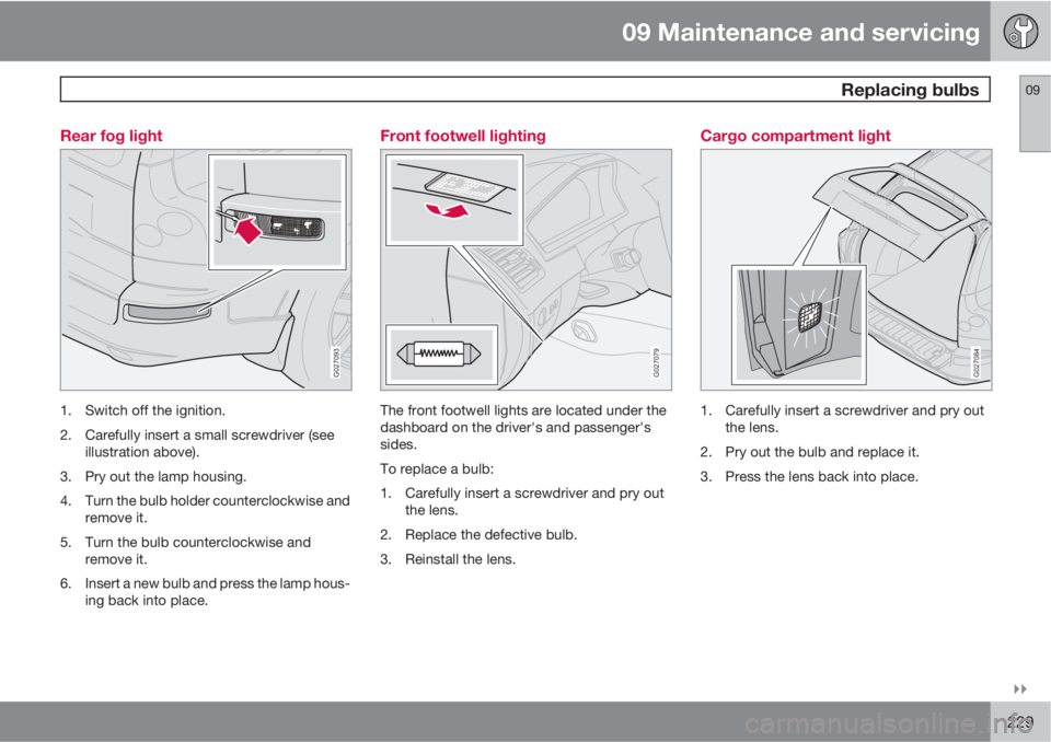
229 Rear fog light
G027093
1. Switch off the ignition.
2. Carefully insert a small screwdriver (see
illustration above).
3. Pry out the lamp housing.
4. Turn the bulb holder counterclockwise and
remove it.
5. Turn the bulb counterclockwise and
remove it.
6. Insert a new bulb and press the lamp hous-
ing back into place.
Front footwell lighting
G027079
The front footwell lights are located under the
dashboard on the driver's and passenger's
sides.
To replace a bulb:
1. Carefully insert a screwdriver and pry out
the lens.
2. Replace the defective bulb.
3. Reinstall the lens.
Cargo compartment light
G027084
1. Carefully insert a screwdriver and pry out
the lens.
2. Pry out the bulb and replace it.
3. Press the lens back into place.
Page 232 of 302

09 Maintenance and servicing
Fuses 09
232* Option/accessory, for more information, see Introduction.
Replacing fuses
G032337
Relays/fuse box in the engine compart-
ment
Fuse box in the passenger compartment,
behind the plastic cover
Fuse box in the passenger compartment,
on the edge of the dashboard
Fuse box in the cargo compartment
Fuse box in the cargo compartment1.
Additional fuses in cargo compartment
(XC90 Executive*)If an electrical component fails to function, it is
possible that a fuse has blown.
The fuse boxes are located in four different
places, see the illustration above.
A label on the inside of each cover indicates the
amperage and the electrical components that
are connected to each fuse.
The easiest way to see if a fuse is blown is to
remove it. Pull the fuse straight out. If a fuse is
difficult to remove, you will find a special fuse
removal tool (and several extra fuses) in the
passenger compartment fuse box on the driv-er's end of dashboard. From the side, examine
the curved metal wire (see the illustration) to
see if it is broken. If so, put in a new fuse of the
same color and amperage (written on the
fuse). Spare fuses are stored in the fuse box in
the engine compartment and the passenger
compartment. If fuses burn out repeatedly,
have the electrical system inspected by a
trained and qualified Volvo service technician.
1Certain markets only.
Page 236 of 302
09 Maintenance and servicing
Fuses 09
236* Option/accessory, for more information, see Introduction.
Fuses in the passenger compartment on the edge of the dashboard
G032316
The decal shows the positions and amperage of the fuses
Fuses are located inside the access panel on
the edge of the dashboard, on the driver's side.
There are also a number of spare fuses. When
replacing a blown fuse, be sure to replace it
with a new one of the same color and amper-
age (written on the fuse).
NoA
1Blower – climate system30
2Audio amplifier*30
3Power driver's seat*25
NoA
4Power passenger's seat*25
5Driver's door – central lock-
ing, power windows, door
mirror25
6Front passenger's door – cen-
tral locking, power windows,
door mirror25
7–
NoA
8Radio, CD player, Rear Seat
Entertainment (RSE)*15
9Volvo Navigation System*,
Sirius satellite radio*10
10On-board diagnostics, head-
light switch, steering wheel
angle sensor, steering wheel
module5
Page 279 of 302
, codes for color and
upholstery, etc. The model plate is located
on the rear side of the B")
11 Specifications
Label information
11
279
Model plate: includes e.g., Vehicle Identi-
fication Number (VIN), codes for color and
upholstery, etc. The model plate is located
on the rear side of the B-pillar (the pillar
between the front and rear passenger
doors) and the rear passenger's door must
be open in order to see it.
Federal Motor Vehicle Safety Standards
(FMVSS) specifications (USA) and Min-
istry of Transport (CMVSS) standards
(Canada): Your Volvo is designed to meet
all applicable safety standards, as evi-
denced by the certification label on the
driver's side B-pillar (the structural mem-
ber at the side of the vehicle, at the rear of
the driver's door opening). For further infor-
mation regarding these regulations, please
consult your Volvo retailer.
Tire inflation pressures: This label indi-
cates the correct inflation pressures for the
tires that were on the vehicle when it left
the factory. Canadian models have the
upper decal; U.S. models have the lower
one.
Vehicle Identification Number (VIN): The
VIN plate is located on the top left surface
of the dashboard. The VIN is also stamped
on the right hand door pillar.
Vehicle Emission Control Information:
Your Volvo is designed to meet all appli-
cable emission standards, as evidenced by
the certification label on the underside of
the hood. For further information regarding
these regulations, please consult your
Volvo retailer.