Page 325 of 374
.
3. Disconnect the wiring connector from the
bulb holder.
4. Remove the bulb holder from")
08 Maintenance and specifications
Replacing bulbs
08
��
325
2. Remove the cover over the bulbs (see
page 323).
3. Disconnect the wiring connector from the
bulb holder.
4. Remove the bulb holder from the headlight
housing by pulling it straight out.
5. Insert a new bulb in the holder until it snaps
in place. It can only be inserted in one way.
6. Press the bulb holder into position in the
headlight housing.
7. Reconnect the wiring connector to the bulb
holder.
8. Put the cover back into position and rein-
stall the headlight housing.
Turn signals
1. Remove the headlight housing from the
vehicle (see page 322).
2. Remove the bulb holder by turning it coun-
terclockwise and pulling it out of the head-
light housing.
3. Pull out the holder to access the bulb.
4. Remove the burned out bulb by pressing it
in slightly and turning it counterclockwise.
5. Press the new bulb into the holder and turn
it clockwise.
6. Reinsert the bulb holder into the headlight
housing and turn it clockwise.
7. Reinstall the headlight housing.
Side marker lights
NOTE
Before starting to replace a bulb, see
page 322.
1. Remove the headlight housing from the
vehicle (see page 322).
2. Remove the bulb holder by turning it coun-
terclockwise and pulling it out of the head-
light housing.
3. Pull out the burned out bulb and install a
new one. It can only be inserted in one
position.
4. Reinsert the bulb holder into the headlight
housing and turn it clockwise.
5. Reinstall the headlight housing.
Page 326 of 374
 can be reached from behind the
bumper
1. Remove the bulb h")
08 Maintenance and specifications
Replacing bulbs
08
326
Rear fog light
The rear fog light (located on the driver's side
of the vehicle) can be reached from behind the
bumper
1. Remove the bulb holder by turning it coun-
terclockwise.
2. Remove the burned out bulb by pressing it
in and turning it counterclockwise.
3. Insert a new bulb, press it in and turn it
clockwise.
4. Reinsert the bulb holder and turn it clock-
wise.
Location of taillight bulbs
Taillight lens, right side
Parking/side marker lights (LED)
Side reflector
Brake light
Backup light
Turn signal
Brake lights (LED)
NOTE
If an error message remains in the display
after a faulty bulb has been replaced, con-
tact an authorized Volvo workshop.
Brake lights and taillights
The brake lights and taillights are replaced from
inside the cargo area.
NOTE
Before starting to replace a bulb, see
page 322.
1. Open the panel.
2. Remove the bulb holder by turning it coun-
terclockwise.
3. Remove the burned out bulb by pressing it
in and turning it counterclockwise.
4. Insert a new bulb, press it in and turn it
clockwise.
5. Reinsert the bulb holder and turn it clock-
wise.
Page 327 of 374
08 Maintenance and specifications
Replacing bulbs
08
��
327 License plate lighting
1. Remove the screws with a screwdriver.
2. Carefully detach the entire bulb housing
and pull it out.
3. Replace the bulb.
4. Reinsert the entire bulb housing and
tighten the screws.
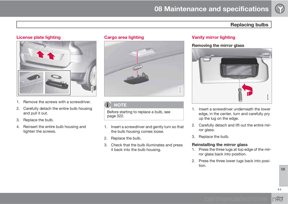
Cargo area lighting
G031942
NOTE
Before starting to replace a bulb, see
page 322.
1. Insert a screwdriver and gently turn so that
the bulb housing comes loose.
2. Replace the bulb.
3. Check that the bulb illuminates and press
it back into the bulb housing.
Vanity mirror lighting
Removing the mirror glass
1. Insert a screwdriver underneath the lower
edge, in the center, turn and carefully pry
up the lug on the edge.
2. Carefully detach and lift out the entire mir-
ror glass.
3. Replace the bulb.
Reinstalling the mirror glass1. Press the three lugs at top edge of the mir-
ror glass back into position.
2. Press the three lower lugs back into posi-
tion.
Page 328 of 374
08 Maintenance and specifications
Replacing bulbs
08
328* Option/accessory, for more information, see Introduction.
Bulb specifications
Lighting
functionWattageBulb
Extra high
beam (models
with Active
Bending
Lights*)55H7 LL
Low beam
(halogen)55H11 LL
High beam
(halogen)65H9
Front turn sig-
nals21PY21W
LL
License plate
lighting5C5W LL
Vanity mirror1.2SV5.5
(length
35mm)
Front side
marker lights5W3W LL
Glove com-
partment
lighting5SV8.5
(length
43mm)
Lighting
functionWattageBulb
Rear fog light21P21W LL
Backup lights21P21W LL
Brake lights21P21W LL
Cargo area
lighting10SV8.5
(length
43mm)
NOTE
Please consult a Volvo retailer’s Parts
department for the most up-to-date speci-
fications.
Page 330 of 374
08 Maintenance and specifications
Wiper blades and washer fluid
08
330
CleaningKeeping the windshield and wiper blades clean
helps improve visibility and prolongs the serv-
ice life of the wiper blades. Clean the wiper
blades with a stiff-bristle brush and lukewarm
soap solution or car washing detergent.
Replacing the tailgate wiper blade
G032770
1. Fold the wiper arm outward.
2. Grasp the inner section of wiper blade (at
the arrow).
3. Pull out the blade to release it from the
wiper arm.
4. Press the new wiper blade into place and
check that it seats securely.
5. Fold the wiper arm back toward the tailgate
window.
Filling washer fluid
Location of the washer fluid reservoir
The windshield and headlight washers share a
common reservoir.
The washer fluid reservoir is located on the
driver's side of the engine compartment. Dur-
ing cold weather, the reservoir should be filled
with windshield washer solvent containing
antifreeze. For capacities, see page 357.
Page 332 of 374

08 Maintenance and specifications
Battery
08
332
WARNING
•Never expose the battery to open flame
or electric spark.
•Do not smoke near the battery.
•Battery fluid contains sulfuric acid. Do
not allow battery fluid to contact eyes,
skin, fabrics or painted surfaces. If con-
tact occurs, flush the affected area
immediately with water. Obtain medical
help immediately if eyes are affected.
NOTE
The life of the battery is shortened if it
becomes discharged repeatedly.
Maintenance
•Use a screw driver to open the caps or
cover and a flashlight to inspect the level.
•If necessary, add distilled water. The level
should never be above the indicator.
•The fluid level should be checked if the
battery has been recharged.
•After inspection, be sure the cap over each
battery cell or the cover is securely in
place.
•Check that the battery cables are correctly
connected and properly tightened.
•Never disconnect the battery when the
engine is running, or when the key is in the
ignition. This could damage the vehicle's
electrical system.
•The battery should be disconnected from
the vehicle when a battery charger is used
directly on the battery.
•To help keep the battery in good condition,
the vehicle should be driven for at least 15
minutes a week or connected to a charger
with an automatic charging function.
•If the battery is fully discharged a number
of times, this may shorten its service life.
Keeping the battery fully charged helps
prolong its service life.
•The service life of a battery is affected by
factors such as driving conditions and cli-
mate. Extreme cold may also further
decrease the battery’s starting capacity.
•Because the battery’s starting capacity
decreases with time, it may be necessary
to recharge it if the vehicle is not driven for
an extended period of time or if the vehicle
is usually only driven short distances.
CAUTION
•Always use distilled or deionized water
(battery water).
•Never fill above the level mark in the cell.
Changing
Page 336 of 374

08 Maintenance and specifications
Fuses
08
336* Option/accessory, for more information, see Introduction.
Engine compartment, upper
Engine compartment, front
Engine compartment, lower
PositionsThese fuses are all located in the engine com-
partment box. Fuses in
are located under
.
NOTE
•Fuses 16 – 33 and 35 – 41 may be
changed at any time when necessary.
•Fuses 1 – 15, 34 and 42 – 44 are relays/
circuit breakers and should only be
removed or replaced by a trained and
qualified Volvo service technician.
•There is a special fuse removal tool on
the underside of the cover.
PosFunctionA
Circuit breaker50
Circuit breaker50
Circuit breaker60
Circuit breaker60
PosFunctionA
Circuit breaker60
–
–
Headlight washers*20
Windshield wipers30
–
Climate system blower40
–
ABS pump40
ABS valves20
–
Active Bending Lights-
headlight leveling*10
Central electrical module20
ABS5
Speed-dependent steering
force*5
PosFunctionA
Engine Control Module
(ECM), transmission, SRS10
Heated washer nozzles*10
-
Lighting panel5
-
-
-
Engine compartment box5
Auxiliary lights*20
Horn15
Engine Control Module
(ECM)10
Control module, automatic
transmission15
Compressor A/C15
Relay coils5
Page 339 of 374

08 Maintenance and specifications
Fuses
08
��
* Option/accessory, for more information, see Introduction.339
PosFunctionA
Power front passenger's
seat*20
Folding rear seat head
restraints*15
Infotainment control mod-
ule5
Infotainment system, Sirius
satellite radio*10
Infotainment system15
Bluetooth hands-free sys-
tem5
Rear Seat Entertainment
system (RSE)*7.5
Laminated panoramic roof*
Courtesy lighting, climate
system sensor5
12-volt sockets15
Heated rear seat* (pas-
senger's side)15
Heated rear seat* (driver's
side)15
PosFunctionA
-
Heated front passenger's
seat*15
Heated driver's seat*15
Park assist*, trailer hitch
control module*, park
assist camera*5
All Wheel Drive* control
module5
Active chassis system*10
Positions-fuse box B
PosFunctionA
Tailgate wiper15
-
Front courtesy lighting,
driver's door power win-
dow controls, power
seat(s)*, HomeLInk
® Wire-
less Control System*
7.5
Instrument panel informa-
tion display5
PosFunctionA
Adaptive cruise control/
collision warning*10
Courtesy lighting, rain sen-
sor*7.5
Steering wheel module7.5
Cental locking: fuel filler
door10
Tailgate window washer15
Windshield washer15
Tailgate unlock10
-10
Fuel pump20
Climate system control
panel
Alarm movement sensor*5
-
Alarm, On-board diagnos-
tic system5
-