Page 292 of 358

07 Wheels and tires
Changing a wheel
07
292
WARNING
•The jack must correctly engage the jack
attachment.
•Be sure the jack is on a firm, level, non-
slippery surface.
•Never allow any part of your body to be
extended under a vehicle supported by
a jack.
•Use the jack intended for the vehicle
when changing a tire. For any other job,
use stands to support the vehicle.
•Apply the parking brake and put the
gear selector in the Park (P) position.
•Block the wheels standing on the
ground, use rigid wooden blocks or
large stones.
•The jack should be kept well-greased
and clean, and should not be damaged.
•No objects should be placed between
the base of jack and the ground, or
between the jack and the attachment
bar on the vehicle.
Re-installing the wheel1. Clean the contact surfaces on the wheel
and hub.
2. Lift the wheel and place it on the hub.
Tighten the lug nuts
3. Install the wheel nuts and tighten hand-
tight. Using the lug wrench, tighten cross-
wise until all nuts are snug.
4. Lower the vehicle to the ground and alter-
nately tighten the bolts crosswise to
103 ft. lbs. (140 Nm).
5. Install the wheel cover (where applicable).
The opening in the wheel cover for the tire's
inflation valve must be positioned over the
valve.
Page 301 of 358

08 Maintenance and specifications
Hood and engine compartment
08
301 Opening and closing the hood
Turn the handle located under the left side
of the dash approximately 20-25 degrees
clockwise to release the hood lock.
Lift the hood slightly. Press the release
control (located under the right front edge
of the hood) to the left, and lift the hood
WARNING
Check that the hood locks properly when
closed.
Engine compartment, overview
The appearance of the engine compartment
may vary depending on engine model.
Coolant expansion tank
Power steering fluid reservoir
Engine oil dipstick
Radiator
Filler cap for engine oil
Cover over brake fluid reservoir
Battery
Relay and fuse box
Washer fluid reservoir
Air cleaner
WARNING
The cooling fan may start or continue to
operate (for up to 6 minutes) after the engine
has been switched off.
WARNING
The ignition should always be completely
switched off before performing any opera-
tions in the engine compartment.
The distributor ignition system operates at
very high voltages. Special safety precau-
tions must be followed to prevent injury.
Always turn the ignition off when:
•Replacing distributor ignition compo-
nents e.g. plugs, coil, etc.
•Do not touch any part of the distributor
ignition system while the engine is run-
ning. This may result in unintended
movements and body injury.
Page 307 of 358

08 Maintenance and specifications
Replacing bulbs
08
��
307
CAUTION
Never touch the glass of bulbs with your fin-
gers. Grease and oils from your fingers
vaporize in the heat and will leave a deposit
on the reflector, which will damage it.
NOTE
•Always switch off the ignition before
starting to replace a bulb.
•The optional Active Bending Light bulbs
contain trace amounts of mercury.
These bulbs should always be disposed
of by a trained and qualified Volvo serv-
ice technician.
Removing the headlight housing1. Switch off the ignition by briefly pressing
the START/STOP ENGINE button.
2. Remove the remote key from the ignition
slot
1.
3. (Upper illustration under "Headlight hous-
ing")
Withdraw the headlight housing's lock-
ing pins.
Remove the headlight housing by alter-
natively pulling the front and rear edges
until it can be lifted out.
CAUTION
When disconnecting the connector, pull on
the connector itself and not on the wiring.
4. (Lower illustration under "Headlight hous-
ing")
Unplug the wiring connector by holding
down the clip with your thumb.
Pull out the connector with the other
hand.
5. Lift out the housing and place it on a soft
surface to avoid scratching the lens.
6. Replace the defective bulb(s).
Reinserting the headlight housing
1. Plug in the connector until it clicks into
place.
2. Reinstall the headlight housing and locking
pins. The short locking pin should be clos-
est to the grille. Check that they are cor-
rectly inserted. The headlight housing must
be properly inserted and secured in place
before the lighting is switched on or the
remote key is inserted into the ignition slot.
3. Check that the lights function properly.
1Does not apply to vehicles with the optional keyless drive.
Page 308 of 358

08 Maintenance and specifications
Replacing bulbs
08
308
Removing the cover to access the
bulbs
NOTE
Before starting to replace a bulb, see
page 306.
1. Loosen the cover's four retaining screws
with the tool (1) provided in the vehicle's
tool kit (see page 290). The screws should
not be removed completely.
CAUTION
Use the tool from the vehicle's tool kit to
loosen the screws. A screwdriver or other
sharp object could scratch the headlight.
2. Push the cover to the side.Reinstall the cover in the reverse order.
Low beam, Halogen
1. Remove the headlight housing from the
vehicle (see page 306).
2. Remove the cover over the bulbs (see
page 308).
3. Unplug the connector from the bulb.
4. Remove the bulb by pulling it straight out.
5. The guide lug on the new bulb should be
straight up when the bulb is inserted into
the holder and the bulb should snap into
place.
6. Put the cover back into position and rein-
stall the headlight housing.
High beam, Halogen
1. Remove the headlight housing from the
vehicle (see page 306).
2. Remove the cover over the bulbs (see
page 308).
3. Remove the bulb by turning it counter-
clockwise and pulling it straight out.
4. Remove the connector from the bulb.
5. Press the new bulb into the socket and turn
it clockwise to put it in place. It can only be
secured in one position.
6. Reinsert the bulb holder into the headlight
housing.
7. Put the cover back into position and rein-
stall the headlight housing.
Page 309 of 358
.
2. Remove the cover over the bulbs (see
page 308).
3. Re")
08 Maintenance and specifications
Replacing bulbs
08
��
309 Extra high beam
2
1. Remove the headlight housing from the
vehicle (see page 306).
2. Remove the cover over the bulbs (see
page 308).
3. Remove the bulb by turning it counter-
clockwise and pulling it straight out.
4. Remove the connector from the bulb.
5. Press the new bulb into the socket and turn
it clockwise to put it in place. It can only be
secured in one position.
6. Put the cover back into position and rein-
stall the headlight housing.
Turn signals
1. Remove the headlight housing from the
vehicle (see page 306).
2. Remove the cover by pulling it straight out.
3. Pull the holder to access the bulb.
4. Press in the bulb and turn it to remove it
from the holder.
5. Press and turn the new bulb into place.
6. Reinsert the bulb holder into the headlight
housing.
7. Put the cover back into position and rein-
stall the headlight housing.
Taillight housing
The bulbs in the taillight cluster are replaced
from inside the trunk (not the LED functions).
NOTE
Before starting to replace a bulb, see
page 306.
1. Remove the covers in the left/right panel to
access the bulb holder.
2. Press the catches together and pull out the
bulb holder.
3. Remove the defective bulb by pressing it in
slightly and it turning counterclockwise
before pulling it out.
2Models with optional Active Bending Lights only.
Page 310 of 358

08 Maintenance and specifications
Replacing bulbs
08
310
4. Insert a new bulb, press it in slightly and
turn it clockwise.
5. Press the bulb holder until it clicks into
place and reinstall the cover.
Location of taillight bulbs
Taillight lens, right side
Brake lights (LEDs)
Brake light
Backup light
Turn signals
Rear fog light (driver’s side only)
NOTE
If an error message remains in the display
after a faulty bulb has been replaced, con-
tact an authorized Volvo workshop.
Backup lights
1. Open the panel on the inside of the trunk
lid.
2. Remove the bulb holder by turning it coun-
terclockwise.
3. Remove the defective bulb by pressing it in
slightly and turning it counterclockwise
before pulling it out.
4. Insert a new bulb, press it in slightly and
turn it clockwise.
5. Put the bulb holder in place and turn it
clockwise.
License plate lighting
1. Remove the screws with a screwdriver.
2. Carefully detach the entire bulb housing
and pull it out.
3. Replace the bulb.
4. Reinsert the entire bulb housing and
tighten the screws.
Page 323 of 358
08 Maintenance and specifications
Fuses
08
��
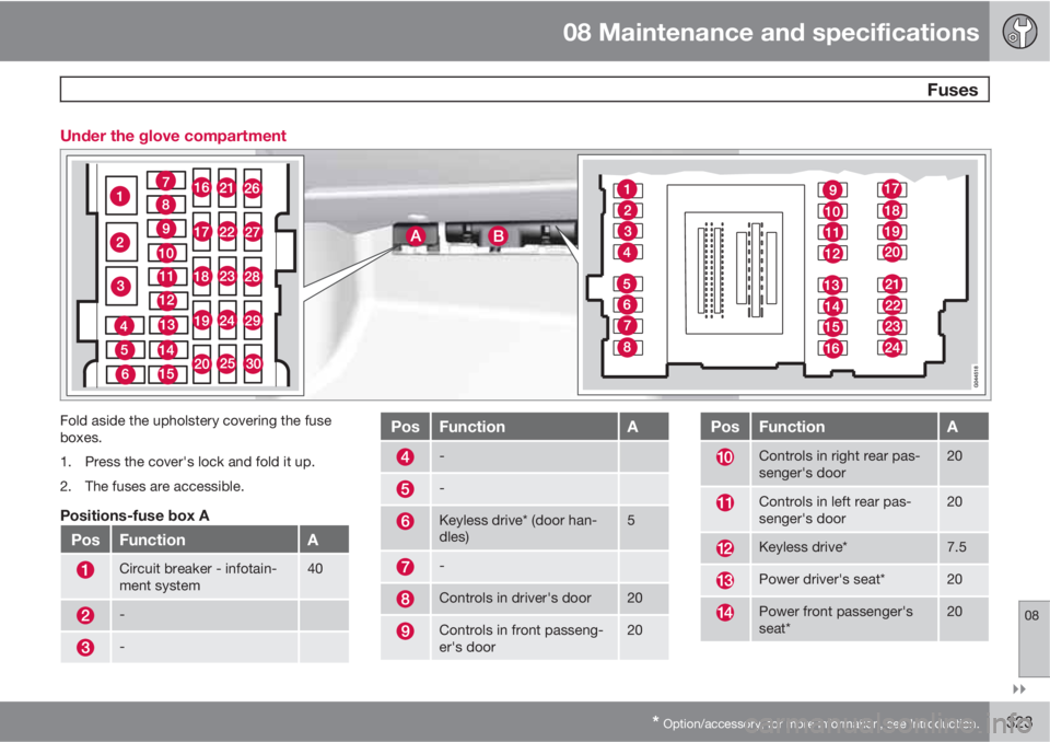
* Option/accessory, for more information, see Introduction.323 Under the glove compartment
Fold aside the upholstery covering the fuse
boxes.
1. Press the cover's lock and fold it up.
2. The fuses are accessible.
Positions-fuse box A
PosFunctionA
Circuit breaker - infotain-
ment system40
-
-
PosFunctionA
-
-
Keyless drive* (door han-
dles)5
-
Controls in driver's door20
Controls in front passeng-
er's door20
PosFunctionA
Controls in right rear pas-
senger's door20
Controls in left rear pas-
senger's door20
Keyless drive*7.5
Power driver's seat*20
Power front passenger's
seat*20
Page 324 of 358

08 Maintenance and specifications
Fuses
08
324* Option/accessory, for more information, see Introduction.
PosFunctionA
Folding rear seat head
restraints15
Infotainment control mod-
ule5
Infotainment system, Sirius
satellite radio*10
Infotainment system15
Bluetooth hands-free sys-
tem5
-
Power moonroof*
Courtesy lighting, climate
system sensor5
12-volt sockets15
Heated rear seat* (pas-
senger's side)15
Heated rear seat* (driver's
side)15
-
Heated front passenger's
seat*15
PosFunctionA
Heated driver's seat*15
Park assist*, trailer hitch
control module*, park
assist camera*
Blind Spot Information Sys-
tem (BLIS)*5
All Wheel Drive* control
module5
Active chassis system*10
Positions-fuse box B
PosFunctionA
-
-
Front courtesy lighting,
driver's door power win-
dow controls, power
seat(s)*, HomeLInk
® Wire-
less Control System*
7.5
Instrument panel informa-
tion display5
PosFunctionA
Adaptive cruise control/
collision warning*10
Courtesy lighting, rain sen-
sor*7.5
Steering wheel module7.5
Cental locking: fuel filler
door10
-
Windshield washer15
Trunk open10
-10
Fuel pump20
Climate system control
panel5
-
Alarm, On-board diagnos-
tic system5
-