2012 VOLKSWAGEN TRANSPORTER display
[x] Cancel search: displayPage 123 of 486
Do not attach external navigation devices to the windscreen or near interior automatic anti-dazzle
Manual anti-dazzle interior mirror
• Basic position: the lever on the lower part of the mirror is pointing towards the windscreen.
• Pull the lever to the back to select the anti-daz-zle function 99.
Exterior mirrors
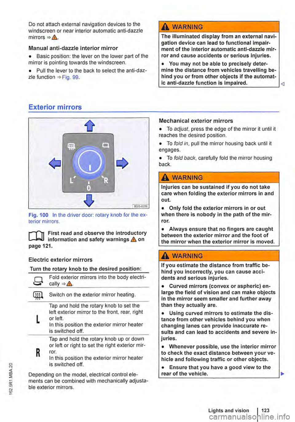
Fig. 100 in the driver door: rotary knob for the ex-terior mirrors.
First read and observe the introductory L..-Jr:.U information and safety warnings & on page 121.
Electric exterior mirrors
Turn the rotary knob to the desired position:
g
L
R
Fold exterior mirrors into the body electri-
Switch on the exterior mirror heating.
Tap and hold the rotary knob to set the left exterior mirror to the front, rear, right or left. In this position the exterior mirror heater is switched off.
Tap and hold the rotary knob up or down or left or right to set the right exterior mir-ror. In this position the exterior mirror heater is switched off.
Depending on the model, electrical control ele-ments can be combined with mechanically adjusta-ble exterior mirrors.
A WARNING
The illuminated display from an external navi-gation device can lead to functional impair-ment of the Interior automatic anti-dazzle mir-ror and cause accidents or serious injuries.
• You may not be able to precisely deter-mine the distance from vehicles travelling be-hind you or from other objects if the automat-ic anti-dazzle function is Impaired.
• To adjust, press the edge of the mirror it until it reaches the desired position.
• To fold in, pull the mirror housing back until it engages.
• To fold back, carefully fold the mirror housing back.
A WARNING
Injuries can be sustained if you do not take care when folding the exterior mirrors in and out.
• Only fold the exterior mirrors in or out when there is nobody in the path of the mir-ror.
• Always ensure that no fingers are caught between the exterior mirror and the foot of the mirror when the exterior mirror is moved.
A WARNING
If you estimate the distance from traffic be-hind you Incorrectly, you can cause acci-dents and serious injuries.
• Curved mirrors (convex or aspheric) en-large the field of vision and can make objects in the mirror seem smaller and further away than they actually are.
• Using curved mirrors to estimate the dis-tance from other vehicles behind you when changing lanes can provide inaccurate re-sults and can lead to accidents and severe in-juries.
• Whenever possible, use the interior mirror to check the exact distance between your ve-hicle and following traffic or other objects.
• Ensure that you have a good view to the rear of the vehicle. .,..
Lights and vision 123
Page 168 of 486
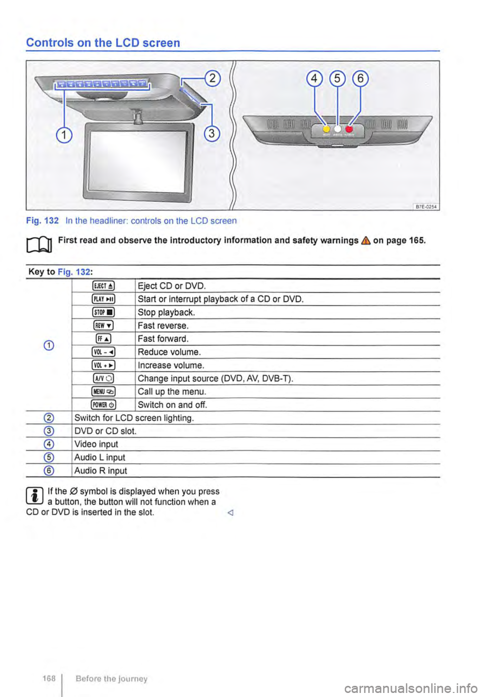
Controls on the LCD screen
Fig. 132 In the headliner: controls on the LCD screen
m First read and observe the Introductory Information and safety warnings & on page 165.
Key to Fig 132·
Eject CD or DVD.
illAY •uJ Start or interrupt playback of a CD or DVD.
lsTor•l Stop playback.
IREW ,.] Fast reverse.
G) ([;) Fast forward.
lvOl--.) Reduce volume.
lvOl • •I Increase volume.
IA/YO) Change input source (DVD, AV, DVB-T).
lllli.JQ,) Call up the menu.
IPOm) Switch on and off.
® Switch for LCD screen lighting.
@ DVD or CD slot.
® Video input
® Audio L input
® Audio R input
rll If the 0 symbol is displayed when you press L!.J a button. the button will not function when a CD or DVD is inserted in the slot.
Page 170 of 486

Key to Fig 133·
8REW8FWD Fast forward or reverse during playback. Press the button repeatedly to increase forward or reverse speed. If the§) button is pressed be-forehand, the slow-motion function has been activated.
@ §)PREY 81£XT Change to previous or next title/chapter.
§) PLAY /PAUSE Press once to start or interrupt playback. Press twice during playback and then press the B or 8 button to jump from scene to scene.
@STOP Stop playback.
Call up settings menu for the screen.
© (!) U/D(CH) Q no function
@ (!)VO!.Q Increase or lower the volume.
®l Switch sound on and off.
@ (ij ... (i) Numerical buttons
® @ Repeat the section selected between the first and second time the button was pressed.
@ Zoom into the current image. Press the button repeatedly to increase the zoom factor and finally to switch the zoom function off.
@ @) Switch repeat function on and off.
@ Skip to a chapter or piece of music.
@ §D Call up the TITLE menu of the DVD.
@ @ Select subtitles of DVDs with a multi-lingual subtitle function.
Replacing the battery
If the remote control unit no longer reacts when you press a button. the battery is empty and must be replaced.
• Slide open the cover on the rear of the remote control unit.
• Using a suitable thin object, lever the battery out of the battery compartment.
• Insert a new battery in the direction of the arrow 134
• Close the cover.
Swallowing batteries with a diameter of 20 mm or other lithium batteries can result in severe or even fatal injuries within a very short period of time.
• Always keep the remote control unit, key ring with batteries, spare batteries, round cells and other batteries that are larger than 20 mm out of the reach of children.
Settings on the LCD screen
rl'11 First read and observe the introductory L-W.f information and safety warnings & on page 165.
170 I Before the journey
• Call for medical help immediately you sus-pect that someone has swallowed a battery.
CD
• The remote control can be damaged if the battery is not changed properly.
• Unsuitable batteries can damage the remote control. Replace discharged batteries only with new batteries of the same voltage rating, size and specification.
• Ensure that the battery Is fitted the right way round.
Dispose of discharged batteries in accord-W ance with regulations governing the protec-tion of the environment.
r::l If the 0 symbol is displayed when you press l!J a button, the button will not function when a CD or DVD is inserted in the slot.
Page 172 of 486
• Press the [ENTER! button to confirm your selec-tion.
• Press the [SETUP! button again to leave the main menu.
The following settings can be made in the subme-nus:
• Picture format.
• Camera perspective.
• Language.
• Subtitles.
• Screen saver.
• Saving the last item played.
Tachograph
o::D Introduction
This chapter contains information on the following subjects:
Notes on the tachograph . . . . . . . . . . . . . . . . . 172
The function and operation of the factory-fitted ta-chograph can be found in an additional operating manual delivered with the vehicle.
If you retro-fit a tachograph to the vehicle, ensure it complies with relevant legislation.
Additional information and warnings:
• Towing a trailer 139
• Accessories. modifications, repairs and renewal of parts 394
Notes on the tachograph
I""'""'J'n First read and observe the Introductory L-lo:.l.l Information given on page 172.
Location
Depending on the model, the factory-fitted tacho-graph could be located in the middle of the dash panel or in a console on the dash panel.
Time
For the time settings, refer to the additional operat-ing instructions for the tachograph.
Please note that in digital tachographs, the time must be displayed in local time. The time on the printouts is always given in UTC (Coordinated Uni-versal Time).
1721 Before the journey
• Various audio settings.
• Colour system.
• Playback control for video COs
• Parental lock 172.
• Reset to default settings.
• Password protection.
Childproof locks
This function is only available in the case of DVDs with restricted access for young people and chil-dren. This menu is used to specify whether a DVD with access restrictions is to be played or whether a password has to be entered first.
m Manipulation of the tachograph and its signal, l.!J and misuse of the tachograph discs can re-sult in prosecution.
The digital tachograph has a buffer battery to pre-vent data loss. The buffer battery can supply power for approx. one year without an external power supply. This function is used if, for example, the digital tachograph is removed from the vehicle and stored or if left in a vehicle with a battery fault or a flat battery.
Legal requirements
By law. the tachograph must be used in:
Page 173 of 486
• Vehicles whose gross vehicle weight rating, in-cluding trailer exceeds 3,500 kg, if the vehicle is used commercially to transport goods. This is irre-spective of whether the vehicle or the trailer or both are used for commercial transportation of goods.
• Vehicles which are built and fitted for the pur-pose of carrying more than 9 persons, including the driver.
Checking the tachograph
The tachograph must be checked by the manufac-turer or an authorised workshop if any of the fol-lowing occurs, either in isolation or as a combina-tion:
Digital voice enhancement
ClJJ Introduction
This chapter contains information on the following subjects:
Using the digital voice enhancement . . . . . . . . 173
The digital voice enhancement (DVE) enables all vehicle occupants to hear each other clearly, even at high speeds. The driver can communicate with the occupants in the passenger compartment with out having to turn around or speak loudly.
The voice signals from the driver are recorded via a microphone in the headliner. Then, the signals are amplified and mixed with the radio or media
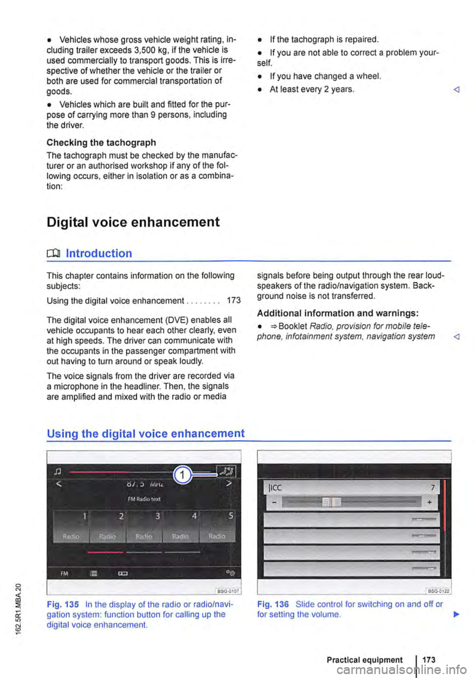
Using the digital voice enhancement
Fig. 135 In the display of the radio or radio/navi-gation system: function button for calling up the digital voice enhancement.
• If the tachograph is repaired.
• If you are not able to correct a problem your-self.
• If you have changed a wheel.
• At least every 2 years.
Additional information and warnings:
• Booklet Radio, provision for mobile tele-phone, infotainment system, navigation system
Fig. 136 Slide control for switching on and off or
Practical equipment 1173
Page 190 of 486
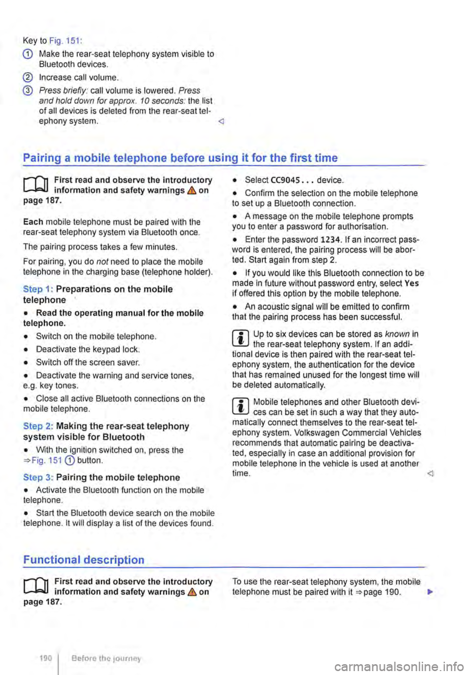
Key to Fig. 151:
G) Make the rear-seat telephony system visible to Bluetooth devices.
@ Increase call volume.
@ Press briefly: call volume is lowered. Press and hold down for approx. 10 seconds: the list of all devices is deleted from the rear-seat tel-ephony system.
il""'n First read and observe the introductory L--i=J.I information and safety warnings & on page 187.
Each mobile telephone must be paired with the rear-seat telephony system via Bluetooth once.
The pairing process takes a few minutes.
For pairing, you do not need to place the mobile telephone in the charging base (telephone holder).
Step 1: Preparations on the mobile telephone
• Read the operating manual for the mobile telephone.
• Switch on the mobile telephone.
• Deactivate the keypad lock.
• Switch off the screen saver.
• Deactivate the warning and service tones, e.g. key tones.
• Close all active Bluetooth connections on the mobile telephone.
Step 2: Making the rear-seat telephony system visible for Bluetooth
• With the ignition switched on, press the 151 G) button.
Step 3: Pairing the mobile telephone
• Activate the Bluetooth function on the mobile telephone.
• Start the Bluetooth device search on the mobile telephone. it will display a list of the devices found.
Functional description
il""'n First read and observe the introductory L--i=J.I information and safety warnings & on page 187.
190 I Before the journey
• Select CC9045 ... device.
• Confirm the selection on the mobile telephone to set up a Bluetooth connection.
• A message on the mobile telephone prompts you to enter a password for authorisation.
• Enter the password 1234. If an incorrect pass-word is entered, the pairing process will be abor-ted. Start again from step 2.
• If you would like this Bluetooth connection to be made in future without password entry, select Yes if offered this option by the mobile telephone.
• An acoustic signal will be emitted to confirm that the pairing process has been successful.
m Up to six devices can be stored as known in L!.J the rear-seat telephony system. If an addi-tional device is then paired with the rear-seat tel-ephony system, the authentication for the device that has remained unused for the longest time will be deleted automatically.
m Mobile telephones and other Bluetooth devi-L!.J ces can be set in such a way that they auto-matically connect themselves to the rear-seat tel-ephony system. Volkswagen Commercial Vehicles recommends that automatic pairing be deactiva-ted, especially in case an additional provision for mobile telephone in the vehicle is used at another time.
Page 204 of 486

Central control panel, California
COl Introduction
This chapter contains information on the following subjects:
Controls . . . . . . . . . . . . . . . . . . . . . . . . . . . . . . . 204
Display . . . . . . . . . . . . . . . . . . . . • . . . . 205
Menu structure . . . . . . . . . . . . . . . . . . . . . . . . . . 206 Programming the wake up time . . . . . . . • . . . . 207
Programming the countdown timer . . . . . . . . . 207
The central control panel is the "control and infor-mation centre" for the camping equipment. The central control panel can be used to open and con-trol the following displays and functions:
• Opening and closing the electric pop-up roof 221
• Displays showing the ambient temperature, clock and charging status of the additional batter-ies 205
Controls
• Switching the refrigerator box on and off or set-ting the temperature =>page 241
• Status display and control of supplementary heater 251
• Programming countdown timer 207
• Programming the wake up time 207
• Setting the clock
Additional information:
• Cleaning the central control panel 254
• Rectifying faults on the camping equipment 254
q Donnerstag g
Fig. 168 In the headliner: central control panel with the initial screen
ro First read and observe the Introductory Information given on page 204.
Button, control
204 I
Additional Information 168.
To switch the supplementary heating system on and off and to set the temperature
Display
To switch the refrigerator box on and off and to adjust its temperature
Rotary/push knob to select and confirm menu entries
Before the journey
Page 205 of 486
Button, control
Display
®
Additional information =>Fig. 168.
To return to initial screen or cancel a setting without saving it
To completely switch off all functions which were activated using the central control panel, e.g. supplementary heating system, refrigerator box, and wake-up time <1
1 9.5 ° c
Fr f."l11 :28
0
Pj
3
0 117H-01S9
First read and observe the introductory lnfonmation given on page 204.
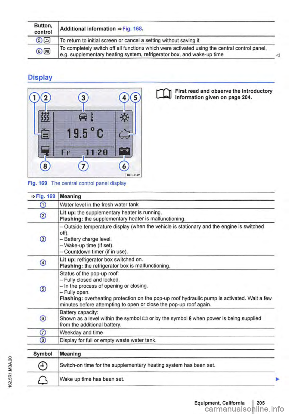
Fig. 169 The central control panel display
=>Fig. 169 Meaning
CD Water level in the fresh water tank
® Lit up: the supplementary heater is running. Flashing: the supplementary heater is malfunctioning.
-Outside temperature display (when the vehicle is stationary and the engine is switched
@ off). -Battery charge level. -Wake-up time (if set). -Countdown timer (if in use).
@ Lit up: refrigerator box switched on. Flashing: the refrigerator box is malfunctioning.
Status of the pop-up roof: -Fully closed and locked.
® -In the process of opening or closing. -Fully open. Flashing: overheating protection on the pop-up roof hydraulic pump is activated. Wait a few minutes before attempting to open or close the pop-up roof again.
Battery capacity:
® Shown as a level within the symbol o or by the symbol G when power is being supplied from the additional battery.
Symbol Meaning
Switch-on time for the supplementary heating system has been set.
Wake up time has been set.
Equipment, California 1205