Page 268 of 400
268
4-3. Do-it-yourself maintenance
Air conditioning filter
The air conditioning filter must be changed regularly to maintain air
conditioning efficiency.
■ Replacement method
Turn the engine switch to the “LOCK” position.
Open the glove box. Slide off
the damper.
Push in each side of the glove
box to disconnect the upper
claws.
Pull out the glove box and dis-
connect the lower claws.
Page 269 of 400
269
4-3. Do-it-yourself maintenance
4
Maintenance and care
■
Checking interval
Inspect and replace the air conditioning filter according to the maintenance
schedule. In dusty areas or areas with heavy traffic flow, early replacement
may be required. (For scheduled maintenance information, please refer to
the “Scheduled Maintenance Guide” or “Owner’s Manual Supplement”.)
■ If air flow from the vents decreases dramatically
The filter may be clogged. Check the filter and replace if necessary.
NOTICE
■When using the air conditioning system
Make sure that a filter is always installed.
Using the air conditioning system without a filter may cause damage to the
system.
Remove the filter cover.
Remove the air conditioning
filter and replace it with a new
one.
The “ UP” marks shown on the
filter should be pointing up.
Page 279 of 400

279
4-3. Do-it-yourself maintenance
4
Maintenance and care
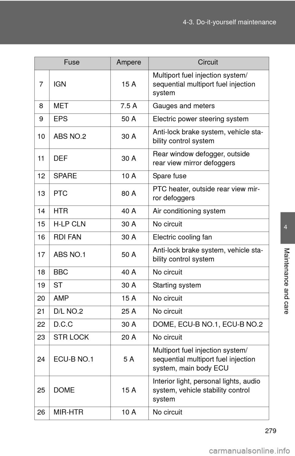
7 IGN
15 AMultiport fuel injection system/
sequential multiport fuel injection
system
8 MET 7.5 A Gauges and meters
9 EPS 50 A Electric power steering system
10 ABS NO.2 30 AAnti-lock brake system, vehicle sta-
bility control system
11 DEF 30 ARear window defogger, outside
rear view mirror defoggers
12 SPARE 10 A Spare fuse
13 PTC 80 APTC heater, outside rear view mir-
ror defoggers
14 HTR 40 A Air conditioning system
15 H-LP CLN 30 A No circuit
16 RDI FAN 30 A Electric cooling fan
17 ABS NO.1 50 AAnti-lock brake system, vehicle sta-
bility control system
18 BBC 40 A No circuit
19 ST 30 A Starting system
20 AMP 15 A No circuit
21 D/L NO.2 25 A No circuit
22 D.C.C 30 A DOME, ECU-B NO.1, ECU-B NO.2
23 STR LOCK 20 A No circuit
24 ECU-B NO.1 5 A Multiport fuel injection system/
sequential multiport fuel injection
system, main body ECU
25 DOME 15 AInterior light, personal lights, audio
system, vehicle stability control
system
26 MIR-HTR 10 A No circuit
FuseAmpereCircuit
Page 283 of 400
283
4-3. Do-it-yourself maintenance
4
Maintenance and care
Under the driver’s side instrument panel
FuseAmpereCircuit
1 TAIL NO.2 10 A Parking lights, tail lights, license
plate lights, side marker lights
2 PANEL 5 A Gauges and meters, instrument
panel lights, switch illumination
3 DOOR R/R 20 A Power windows
4 DOOR P 20 A Power windows
5 ECU-IG NO.1 5 A Electric cooling fan, rear window
defogger, vehicle stability control
system, electric power steering
system, main body ECU, wireless
remote control system, tire pres-
sure warning system
6 ECU-IG NO.2 5 A Vehicle stability control system
7 A/C 7.5 AAir conditioning system, rear win-
dow defogger, outside rear view
mirror defoggers
8 GAUGE 10 ABack-up lights, shift lock control
system, audio system, charging
system, multiport fuel injection sys-
tem/sequential multiport fuel injec-
tion system
9 WASHER 15 A Windshield washer
10 WIPER 20 A Windshield wiper
11 WIPER RR 15 A Rear window wiper
Page 331 of 400

5
When trouble arises
331
5-2. Steps to take in an emergency
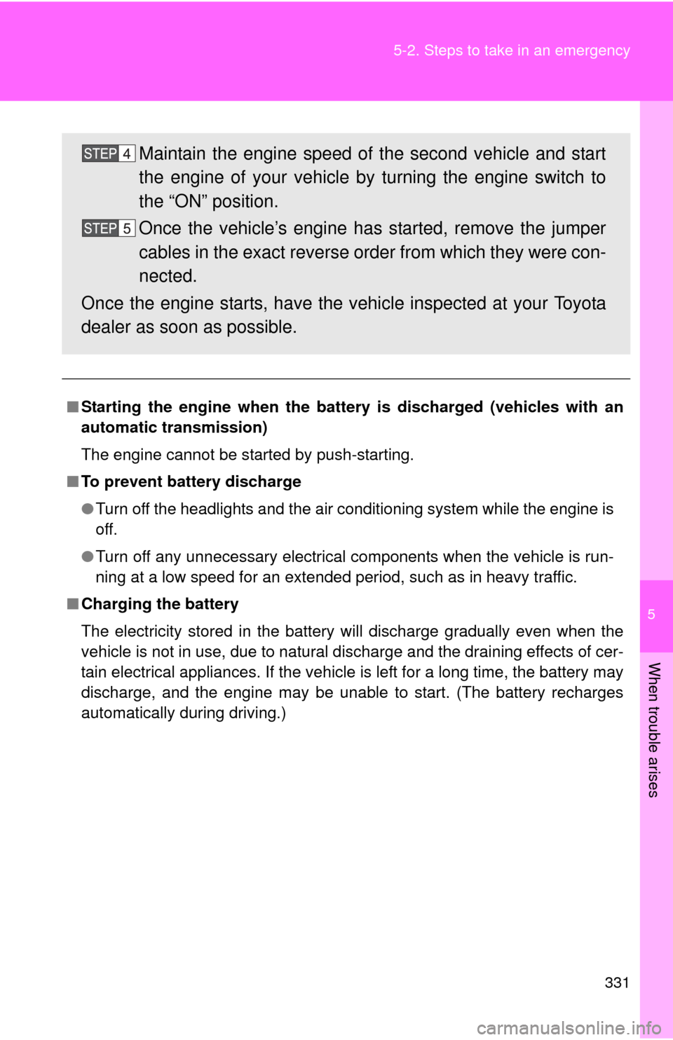
■
Starting the engine when the battery is discharged (vehicles with an
automatic transmission)
The engine cannot be started by push-starting.
■ To prevent battery discharge
●Turn off the headlights and the air conditioning system while the engine is
off.
● Turn off any unnecessary electrical components when the vehicle is run-
ning at a low speed for an extended period, such as in heavy traffic.
■ Charging the battery
The electricity stored in the battery will discharge gradually even when the
vehicle is not in use, due to natural discharge and the draining effects of cer-
tain electrical appliances. If the vehicle is left for a long time, the battery may
discharge, and the engine may be unable to start. (The battery recharges
automatically during driving.)
Maintain the engine speed of the second vehicle and start
the engine of your vehicle by turning the engine switch to
the “ON” position.
Once the vehicle’s engine has started, remove the jumper
cables in the exact reverse or der from which they were con-
nected.
Once the engine starts, have the vehicle inspected at your Toyota
dealer as soon as possible.
Page 345 of 400
345
6-1. Specifications
6
Vehicle specifications
Engine
Model
1NZ-FE
Type 4-cylinder in line, 4-cycle, gasoline
Bore and stroke 2.95 3.33 in. (75.0 84.7 mm)
Displacement 91.3 cu.in. (1497 cm3)
Drive belt tension 68 — 90 lbf (300 — 400 N, 31 — 41kgf)
*
Vehicles without an air conditioning system:
Vehicles with an air conditioning system:
*: Drive belt tension measured with Boroughs drive belt
tension gauge No. BT-33-73F when the engine is cold
(used belt)
Generator
Water pump
Crankshaft
Generator
Water pump Air
conditioning
compressor
Crankshaft
Page 362 of 400

362 6-1. Specifications
Warning: The temperature grades of a tire assume that it is properly
inflated and not overloaded.
Excessive speed, underinflation, or excessive loading, either sepa-
rately or in combination, can cause heat buildup and possible tire fail-
ure.
Glossary of tire terminology
Tire related termMeaning
Cold tire inflation pres-
sure
Tire pressure when the vehicle has been
parked for three hours or more, or has not
been driven more than 1 mile or 1.5 km under
that condition
Maximum inflation
pressureThe maximum cold inflated pressure to which a
tire may be inflated, s hown on the sidewall of
the tire
Recommended infla-
tion pressureCold tire inflation pressure recommended by a
manufacturer
Accessory weight
The combined weight (in excess of those stan-
dard items which may be replaced) of auto-
matic transmission, power steering, power
brakes, power windows, power seats, radio
and heater, to the extent that these items are
available as factory-installed equipment
(whether installed or not)
Curb weight
The weight of a motor vehicle with standard
equipment, including the maximum capacity of
fuel, oil and coolant, and if so equipped, air
conditioning and additional weight optional
engine
Maximum loaded vehi-
cle weight
The sum of:
(a) Curb weight
(b) Accessory weight
(c) Vehicle capacity weight
(d) Production options weight
Page 386 of 400
386
Abbreviation list
Abbreviation/Acronym list
ABBREVIATIONSMEANING
A/C Air Conditioning
ABS Anti-Lock Brake System
ACC Accessory
AI-SHIFT Artificial Intelligence Shift Control ALR Automatic Locking Retractor
CRS Child Restraint System
ECU Electronic Control Unit
EDR Event Data Recorder ELR Emergency Locking Retractor
EPS Electric Power Steering
GAWR Gross Axle Weight Ratings
GVWR Gross Vehicle Weight Rating I/M Emission inspection and maintenance
LATCH Lower Anchors and Tethers for Children LED Light Emitting Diode
M + S Mud + Snow
MMT Methylcy clopentadienyl Manganese Tricarbonyl
MTBE Methyl Tertiary Butyl Ether OBD On Board Diagnostics
SRS Supplemental Restraint System TIN Tire Identification Number
TPMS Tire Pressure Warning System
TRAC Traction Control TWI Treadwear IndicatorsVIN Vehicle Identification Number
VSC Vehicle Stability Control