2012 SUBARU TRIBECA brake fluid
[x] Cancel search: brake fluidPage 335 of 420
11-4Maintenance and service
guard against getting oil or fluids
in your eyes. If something does
get in your eyes, thoroughly
wash them out with clean water.
. Do not tamper with the wiring of
the SRS airbag system or seat-
belt pretensioner system, or at-
tempt to take its connectors
apart, as that may activate the
system or it can render it inop-
erative. NEVER use a circuit
tester for these wiring. If your
SRS airbag or seatbelt preten-
sioner needs service, consult
your nearest SUBARU dealer.
& Before checking or servicing
in the engine compartment
WARNING
. Always stop the engine and set
the parking brake firmly to pre-
vent the vehicle from moving.
. Always let the engine cool down.
Engine parts become very hot
when the engine is running and
remain hot for some time after
the engine is stopped.
. Do not spill engine oil, engine
coolant, brake fluid or any other fluid on hot engine components.
This may cause a fire.
. Always remove the key from the
ignition switch. When the ignition
switch is in the “ON ”position,
thecoolingfanmayoperate
suddenly even when the engine
is stopped.
& When you do checking or
servicing in the engine com-
partment while the engine is running
WARNING
A running engine can be dangerous.
Keep your fingers, hands, clothing,
hair and tools away from the cooling
fan, belts and any other moving
engine parts. Removing rings,
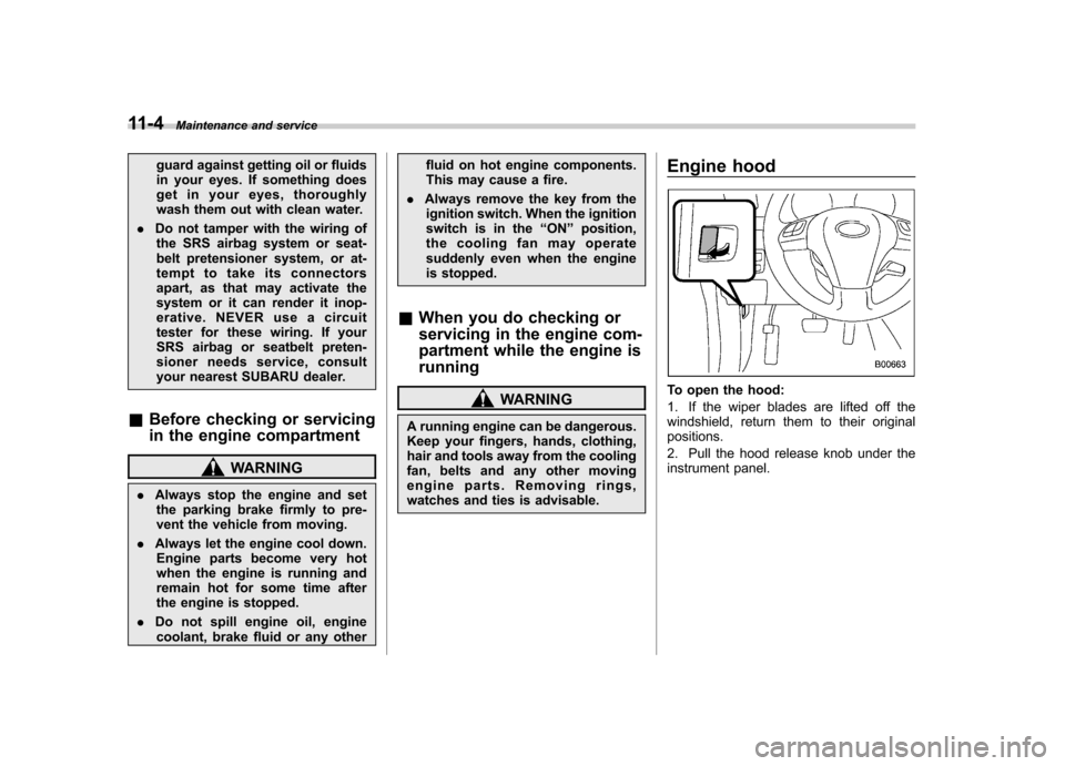
watches and ties is advisable. Engine hoodTo open the hood:
1. If the wiper blades are lifted off the
windshield, return them to their originalpositions.
2. Pull the hood release knob under the
instrument panel.
Page 337 of 420
11-6Maintenance and service
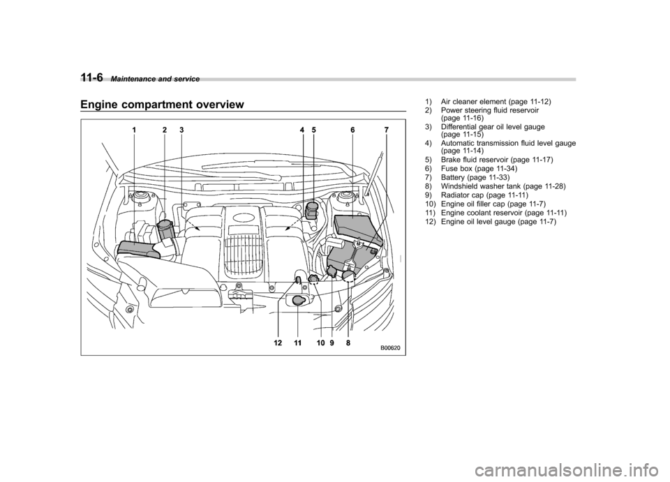
Engine compartment overview1) Air cleaner element (page 11-12)
2) Power steering fluid reservoir
(page 11-16)
3) Differential gear oil level gauge (page 11-15)
4) Automatic transmission fluid level gauge (page 11-14)
5) Brake fluid reservoir (page 11-17)
6) Fuse box (page 11-34)
7) Battery (page 11-33)
8) Windshield washer tank (page 11-28)
9) Radiator cap (page 11-11)
10) Engine oil filler cap (page 11-7)
11) Engine coolant reservoir (page 11-11)
12) Engine oil level gauge (page 11-7)
Page 345 of 420
11-14Maintenance and service
Automatic transmission fluid &Checking the fluid level
The automatic transmission fluid expands
largely as its temperature rises; the fluid
level differs according to fluid temperature.
Therefore, there are two different scales
for checking the level of hot fluid and cold
fluid on the level gauge.
Though the fluid level can be checked
without warming up the fluid on the“ COLD ”range, we recommend checking
the fluid level when the fluid is at operatingtemperature. ! Checking the fluid level when the
fluid is hot
Check the fluid level monthly.
1. Drive the vehicle several miles to raise
the temperature of the transmission fluid
up to normal operating temperature; 158
to 176 8F (70 to 80 8C) is normal.
2. Park the vehicle on a level surface and
set the parking brake.
3. First shift the select lever in each
position. Then shift it in the “P ” position,
and run the engine at idling speed.
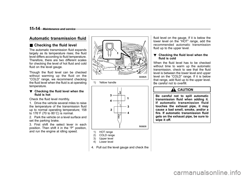
1) Yellow handle
1) HOT range
2) COLD range
3) Upper level
4) Lower level
4. Pull out the level gauge and check the fluid level on the gauge. If it is below the
lower level on the
“HOT ”range, add the
recommended automatic transmission
fluid up to the upper level. ! Checking the fluid level when the
fluid is cold
When the fluid level has to be checked
without time to warm up the automatic
transmission, check to see that the fluid
level is between the lower level and upper
level on the “COLD ”range. If it is below
that range, add fluid up to the upper level.
Be careful not to overfill.
CAUTION
Be careful not to spill automatic
transmission fluid when adding it.
If automatic transmission fluid
touches the exhaust pipe, it may
cause a bad smell, smoke, and/or a
fire. If automatic transmission fluid
gets on the exhaust pipe, be sure to
wipe it off.
Page 348 of 420
power steering fluid touches the
exhaust pipe, it may cause a bad
smell, smoke, and/or a fire. If
power steering fluid gets on the
exhaust pipe, be sure to wipe itoff.
The power steering fluid expands greatly
as its temperature rises; the fluid level
differs according to fluid temperature.
Therefore, the reservoir tank has two
different checking ranges for hot and coldfluids.
Check the power steering fluid level
monthly.
1. Park the vehicle on a level surface,
and stop the engine.
2. Check the fluid level of the reservoir tank.
When the fluid is hot after the vehicle has
been run: Check that the oil level isbetween “HOT MIN ”and “HOT MAX ”on
the surface of the reservoir tank.
When the fluid is cool before the vehicle is
run: Check that the oil level is between“ COLD MIN ”and “COLD MAX ”on the
surface of the reservoir tank.
3. If the fluid level is lower than the
applicable “MIN ”line, add the recom-
mended fluid as necessary to bring the
level between the “MIN ”and “MAX ”line. If the fluid level is extreme low, it may
indicate possible leakage. Consult your
SUBARU dealer for inspection.
& Recommended fluid
Refer to “Fluids ”F 12-7. Brake fluid &
Checking the fluid level
WARNING
. Never let brake fluid contact your
eyes because brake fluid can be
harmful to your eyes. If brake
fluid gets in your eyes, immedi-
ately flush them thoroughly with
clean water. For safety, when
performing this work, wearing
eye protection is advisable.
. Brake fluid absorbs moisture
from the air. Any absorbed moist-
ure can cause a dangerous loss
of braking performance.
. If the vehicle requires frequent
refilling, there may be a leak. If
you suspect a problem, have the
vehicle checked at your SUBARU
dealer.
CAUTION
. When adding brake fluid, be care-
ful not to allow any dirt into the
reservoir.
. Never splash the brake fluid over
painted surfaces or rubber parts. Maintenance and service
11-17
– CONTINUED –
Page 349 of 420
11-18Maintenance and service
Alcohol contained in the brake
fluid may damage them.
. Be careful not to spill brake fluid
when adding it. If brake fluid
touches the exhaust pipe, it may
cause a bad smell, smoke, and/or
a fire. If brake fluid gets on the
exhaust pipe, be sure to wipe itoff.
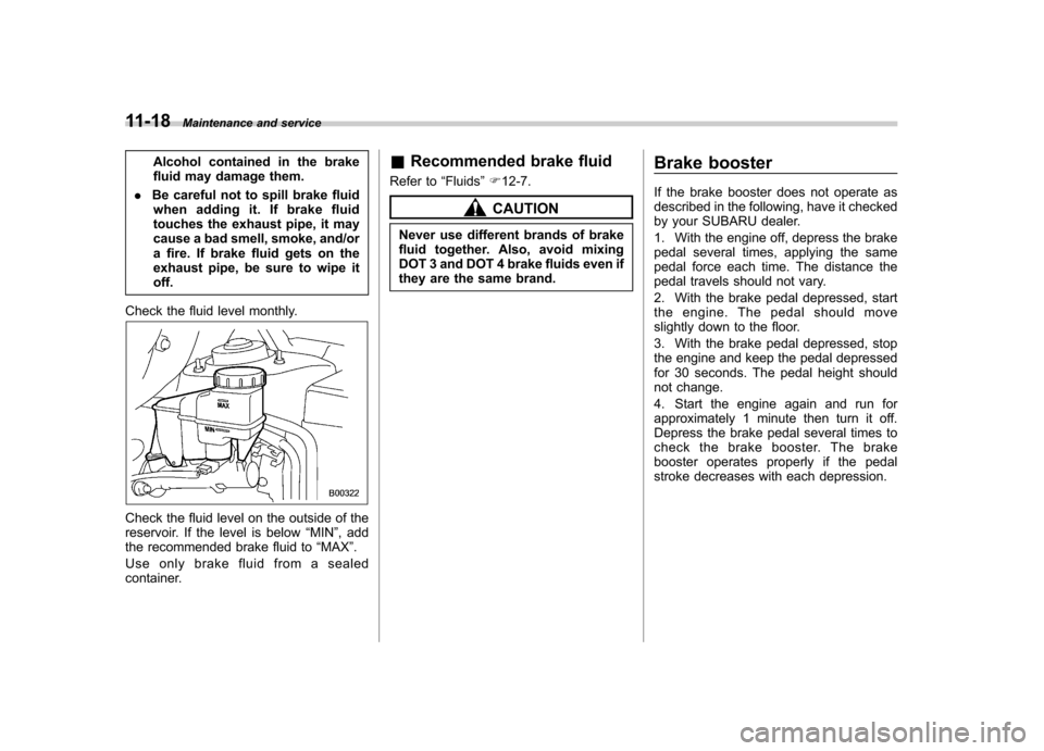
Check the fluid level monthly.
Check the fluid level on the outside of the
reservoir. If the level is below “MIN ”, add
the recommended brake fluid to “MAX ”.
Use only brake fluid from a sealed
container. &
Recommended brake fluid
Refer to “Fluids ”F 12-7.
CAUTION
Never use different brands of brake
fluid together. Also, avoid mixing
DOT 3 and DOT 4 brake fluids even if
they are the same brand. Brake booster
If the brake booster does not operate as
described in the following, have it checked
by your SUBARU dealer.
1. With the engine off, depress the brake
pedal several times, applying the same
pedal force each time. The distance the
pedal travels should not vary.
2. With the brake pedal depressed, start
the engine. The pedal should move
slightly down to the floor.
3. With the brake pedal depressed, stop
the engine and keep the pedal depressed
for 30 seconds. The pedal height should
not change.
4. Start the engine again and run for
approximately 1 minute then turn it off.
Depress the brake pedal several times to
check the brake booster. The brake
booster operates properly if the pedal
stroke decreases with each depression.
Page 382 of 420
&Fluids
Fluid Fluid type*
1Fluid capacity*2Remarks*3
Automatic transmission fluid· SUBARU ATF
· IDEMITSU ATF HP
10.4 US qt (9.8 liters, 8.6 Imp qt)“
Automatic transmission fluid ”F 11 -
14
Power steering fluid · SUBARU ATF
· IDEMITSU ATF HP ·
“Dexron III ”Type Automatic
Transmission Fluid 0.95 US qt (0.9 liters, 0.79 Imp qt)
·
“Power steering ”F 7-18
· “Power steering fluid ”F 11-16
Brake fluid FMVSS No. 116, fresh DOT 3 or DOT 4
brake fluid –
“
Brake fluid ”F 11-17
*1: Use one of the indicated types of fluid.
*2: The indicated fluid quantity is only a guideline. The necessary quantity for replacement may differ slightly depending on the temperature and otherfactors.
*3: For more details about maintenance and service, refer to the indicated section.
& Engine coolant
Coolant type Coolant capacity
SUBARU Super Coolant 8.0 US qt (7.6 liters, 6.7 Imp qt)
The indicated coolant quantity is only a guideline. The necessary quantity for replacement may differ slightly depending on the temperature and other
factors. For more details about maintenance and service, refer to “Cooling system ”F 11-10.
& Electrical system
Battery type and capacity (5HR) 75D23L (12V-52AH)
Alternator 12V-130A
Spark plugs SILFR6C11 (NGK)Specifications
12-7
– CONTINUED –
Page 398 of 420
.Measuring rim
The rim on which a tire is fitted for
physical dimension requirements. . Normal occupant weight
150 lbs (68 kg) times the number of
occupants specified in the second
column of Table 1 that is appended
to the end of this section. . Occupant distribution
Distribution of occupants in a vehi-
cle as specified in the third column
of Table 1 that is appended to the
end of this section. . Open splice
Any parting at any junction of tread,
sidewall, or innerliner that extends
to cord material. . Outer diameter
The overall diameter of an inflated
new tire.. Overall width
The linear distance between the
exteriors of the sidewalls of an
inflated tire, including elevations
due to labeling, decorations, or
protective bands or ribs. .
Passenger car tire
A tire intended for use on passen-
ger cars, multipurpose passenger
vehicles, and trucks, that have a
gross vehicle weight rating (GVWR)
of 10,000 lbs (4,535 kg) or less. . Ply
A layer of rubber-coated parallel cords.. Ply separation
A parting of rubber compound
between adjacent plies.. Pneumatic tire
A mechanical device made of rub-
ber, chemicals, fabric and steel or
other materials, that, when
mounted on an automotive wheel,
provides the traction and contains
the gas or fluid that sustains theload. . Production options weight
The combined weight of those
installed regular production options
weighing over 5.1 lbs (2.3 kg) in
excess of those standard items
which they replace, not previously
considered in curb weight or acces- sory weight, including heavy duty
brakes, ride levelers, roof rack,
heavy duty battery, and special trim. .
Radial ply tire
A pneumatic tire in which the ply
cords that extend to the beads are
laid at substantially 90 degrees to
the centerline of the tread. . Recommended inflation pres-
sure
The cold inflation pressure recom-
mended by a vehicle manufacturer. . Reinforced tire
A tire designed to operate at higher
loads and at higher inflation pres-
sures than the corresponding stan-
dard tire. . Rim
A metal support for a tire or a tire
and tube assembly upon which the
tire beads are seated. . Rim diameter
Nominal diameter of the bead seat. . Rim size designation
Rim diameter and width.
Consumer information and Reporting safety defects
13-7
– CONTINUED –
Page 409 of 420
14-2Index
A Abbreviation ................................................................... 3
ABS (Anti-lock Brake System) ..................................... 7-20
Warning light ................................................. 3-15, 7-21
Accessories ....................................................... 5-2, 11-36
Accessory power outlet ............................................... 6-10
Active head restraint ..................................................... 1-6
Air cleaner element ................................................... 11-12
Air conditioner
Automatic climate control system ............................... 4-5
Air filtration system ..................................................... 4-11
Airflow ........................................................................ 4-2
Airflow mode selection .................................................. 4-3
Airflow selection Automatic climate control system ......................... 4-5, 4-8
Alarm system ............................................................ 2-16
All-Wheel Drive warning light ....................................... 3-18
Aluminum wheel ....................................................... 11-27
Cleaning ............................................................... 10-3
Antenna system ........................................................... 5-2
Anti-lock Brake System (ABS) ..................................... 7-20
Arming the system ..................................................... 2-17
Armrest ..................................................................... 1-13
AT OIL TEMP warning light ......................................... 3-13
Audio Antenna system ....................................................... 5-2
Auxiliary input jack ................................................. 5-28
Control button ........................................................ 5-26
Set......................................................................... 5-3
Auto-dimming mirror/compass .............................. 3-38, 3-41
Automatic climate control system ................................... 4-5 Automatic transmission
............................................... 7-12
Fluid ........................................................... 11-14, 12-7
MANUAL mode ...................................................... 7-16
Oil temperature warning light (AT OIL TEMP) ............. 3-13
Select lever ........................................................... 7-13
Shift lock function ................................................... 7-14
Shift lock release .................................................... 7-14
SPORT mode ........................................................ 7-18
Automatic/Emergency Locking Retractor (A/ELR) ........... 1-18
Auxiliary input jack ...................................................... 5-28
BBattery .................................................................... 11-33
Drainage prevention function ..................................... 2-6
Jump starting ......................................................... 9-11
Replacement (remote keyless entry system) .............. 2-11
Booster seat .............................................................. 1-36
Bottle holder ............................................................... 6-9
Brake Assist .................................................................... 7-19
Booster ....................................................... 7-19, 11-18
Fluid ........................................................... 11-17, 12-7
Pad and lining ...................................................... 11-20
Parking ....................................................... 7-28, 11-20
Pedal .................................................................. 11-19
System .................................................................. 7-19
Brake pedal Free play ............................................................. 11-19
Reserve distance .................................................. 11-19
Brake system ............................................................. 7-19
Warning light .......................................................... 3-16