2012 SUBARU TRIBECA maintenance schedule
[x] Cancel search: maintenance schedulePage 343 of 420
11-12Maintenance and service
Air cleaner element
WARNING
Do not operate the engine with the
air cleaner element removed. The air
cleaner element not only filters
intake air but also stops flames if
the engine backfires. If the air
cleaner element is not installed
when the engine backfires, you
could be burned.
CAUTION
When replacing the air cleaner ele-
ment, use a genuine SUBARU air
cleaner element. If it is not used,
there is the possibility of causing a
negative effect to the engine.
The air cleaner element functions as a
filter screen. When the element is perfo-
rated or removed, engine wear will be
excessive and engine life shortened.
It is unnecessary to clean or wash the element. &
Replacing the air cleaner element
Replace the air cleaner element according
to the maintenance schedule in the“ Warranty and Maintenance Booklet ”. Un-
der extremely dusty conditions, replace it
more frequently. It is recommended that
you always use genuine SUBARU parts.
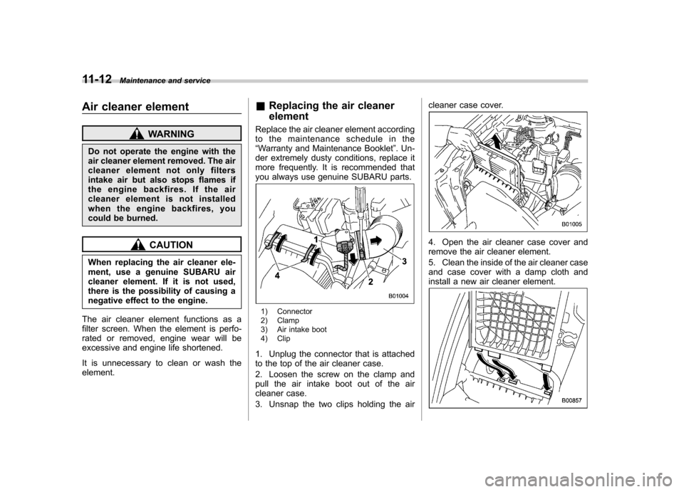
1) Connector
2) Clamp
3) Air intake boot
4) Clip
1. Unplug the connector that is attached
to the top of the air cleaner case.
2. Loosen the screw on the clamp and
pull the air intake boot out of the air
cleaner case.
3. Unsnap the two clips holding the air cleaner case cover.
4. Open the air cleaner case cover and
remove the air cleaner element.
5. Clean the inside of the air cleaner case
and case cover with a damp cloth and
install a new air cleaner element.
Page 344 of 420
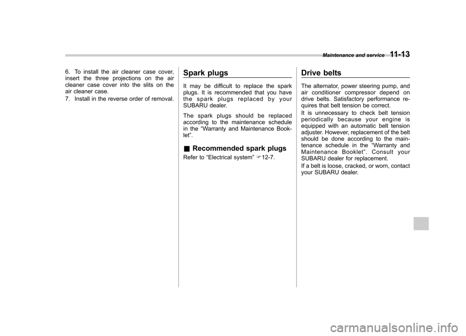
6. To install the air cleaner case cover,
insert the three projections on the air
cleaner case cover into the slits on the
air cleaner case.
7. Install in the reverse order of removal.Spark plugs
It may be difficult to replace the spark
plugs. It is recommended that you have
the spark plugs replaced by your
SUBARU dealer.
The spark plugs should be replaced
according to the maintenance schedule
in the
“Warranty and Maintenance Book-
let ”.
& Recommended spark plugs
Refer to “Electrical system ”F 12-7. Drive belts
The alternator, power steering pump, and
air conditioner compressor depend on
drive belts. Satisfactory performance re-
quires that belt tension be correct.
It is unnecessary to check belt tension
periodically because your engine is
equipped with an automatic belt tension
adjuster. However, replacement of the belt
should be done according to the main-
tenance schedule in the
“Warranty and
Maintenance Booklet ”. Consult your
SUBARU dealer for replacement.
If a belt is loose, cracked, or worn, contact
your SUBARU dealer. Maintenance and service
11-13
Page 350 of 420
Brake pedal
Check the brake pedal free play and
reserve distance according to the main-
tenance schedule in the“Warranty and
Maintenance Booklet ”.
& Checking the brake pedal
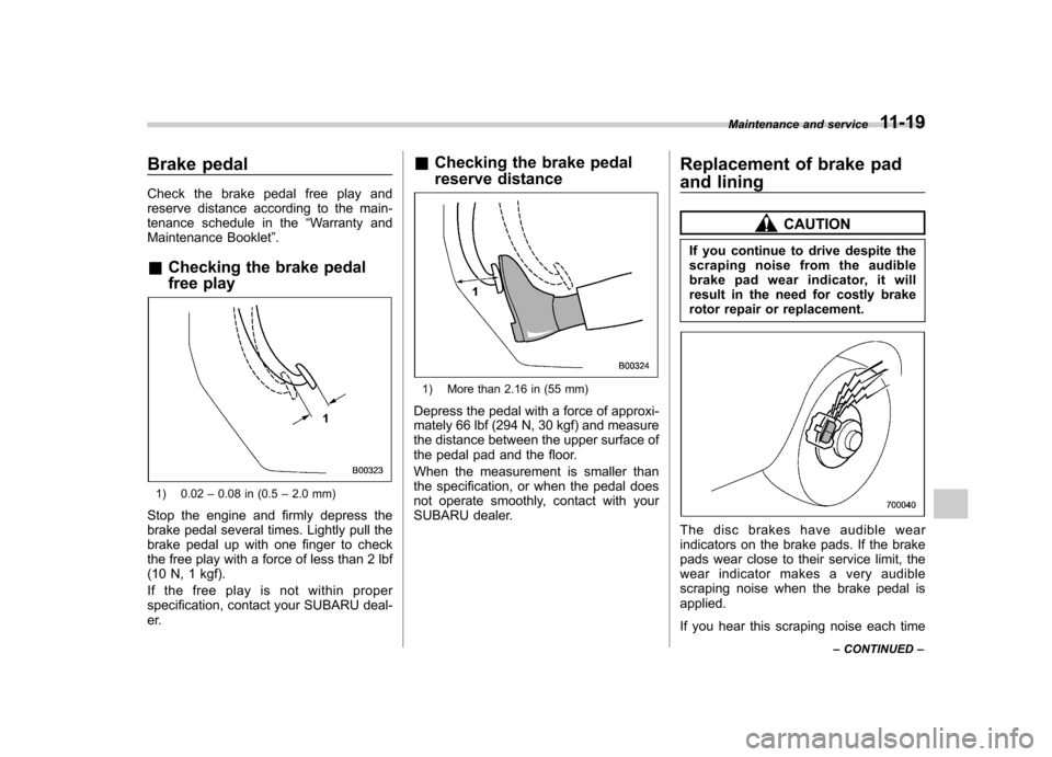
free play
1) 0.02 –0.08 in (0.5 –2.0 mm)
Stop the engine and firmly depress the
brake pedal several times. Lightly pull the
brake pedal up with one finger to check
the free play with a force of less than 2 lbf
(10 N, 1 kgf).
If the free play is not within proper
specification, contact your SUBARU deal-
er. &
Checking the brake pedal
reserve distance
1) More than 2.16 in (55 mm)
Depress the pedal with a force of approxi-
mately 66 lbf (294 N, 30 kgf) and measure
the distance between the upper surface of
the pedal pad and the floor.
When the measurement is smaller than
the specification, or when the pedal does
not operate smoothly, contact with your
SUBARU dealer. Replacement of brake pad
and lining
CAUTION
If you continue to drive despite the
scraping noise from the audible
brake pad wear indicator, it will
result in the need for costly brake
rotor repair or replacement.
The disc brakes have audible wear
indicators on the brake pads. If the brake
pads wear close to their service limit, the
wear indicator makes a very audible
scraping noise when the brake pedal isapplied.
If you hear this scraping noise each time Maintenance and service
11-19
– CONTINUED –
Page 351 of 420
11-20Maintenance and service
you apply the brake pedal, have the brake
pads serviced by your SUBARU dealer as
soon as possible. &Breaking-in of new brake
pads and linings
When replacing the brake pad or lining,
use only genuine SUBARU parts. After
replacement, the new parts must be
broken in as follows. ! Brake pad and lining
While maintaining a speed of 30 to 40
mph (50 to 65 km/h), step on the brake
pedal lightly. Repeat this five or moretimes. ! Parking brake lining
WARNING
A safe location and situation should
be selected for break-in driving.
CAUTION
Pressing the parking brake pedal
too forcefully may cause the rear
wheels to lock. To avoid this, be
certain to press the pedal slowly
and gently. 1. Drive the vehicle at a speed of
approximately 22 mph (35 km/h).
2. Depress the parking brake pedal
SLOWLY and GENTLY. (Pressing with a
force of approximately 34 lbf [150 N, 15kgf].)
3. Drive the vehicle for approximately
220 yards (200 meters) in this condition.
4. Wait 5 to 10 minutes for the parking
brake to cool down. Repeat this proce-dure.
5. Check the parking brake stroke. If the
parking brake stroke is out of the specified
range, adjust it by turning the adjusting nut
located on the parking brake pedal.
Parking brake stroke: 5–6 notches / 67 lbf (300 N, 30 kgf) Parking brake stroke
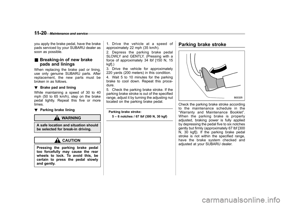
Check the parking brake stroke according
to the maintenance schedule in the“
Warranty and Maintenance Booklet ”.
When the parking brake is properly
adjusted, braking power is fully applied
by depressing the pedal five to six notches
gently but firmly (approximately 67 lbf [300
N, 30 kgf]). If the parking brake pedal
stroke is not within the specified range,
have the brake system checked and
adjusted at your SUBARU dealer.
Page 413 of 420
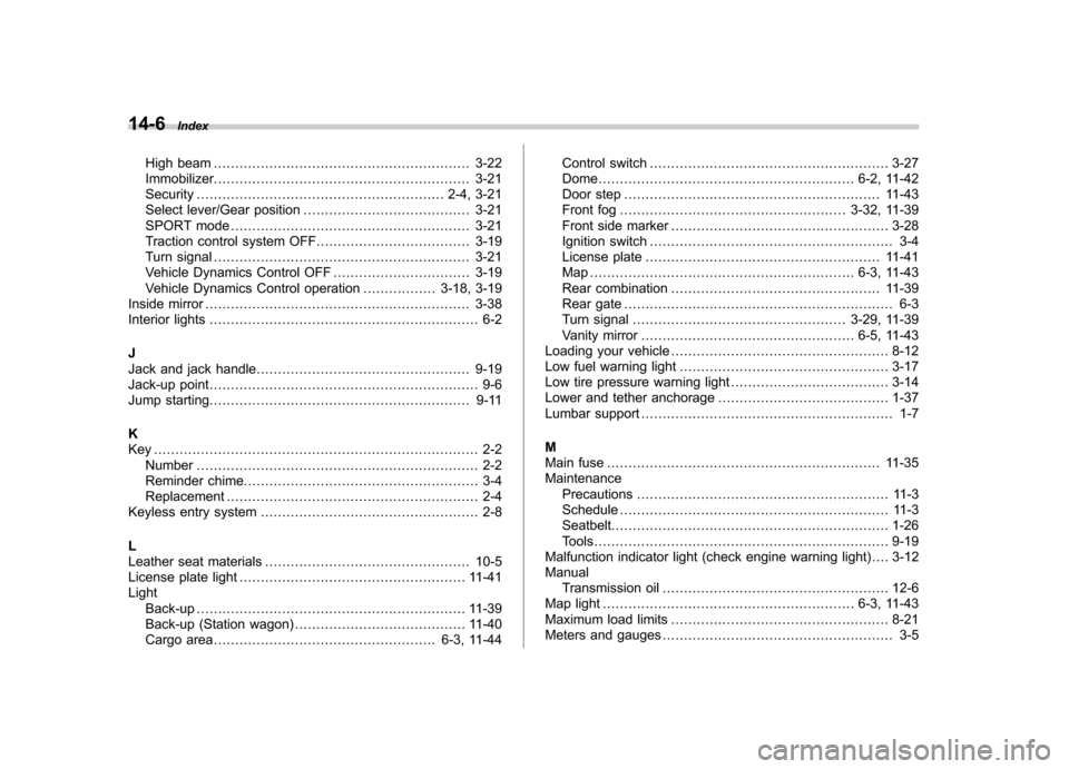
14-6Index
High beam ............................................................ 3-22
Immobilizer. ........................................................... 3-21
Security .......................................................... 2-4, 3-21
Select lever/Gear position ....................................... 3-21
SPORT mode ........................................................ 3-21
Traction control system OFF .................................... 3-19
Turn signal ............................................................ 3-21
Vehicle Dynamics Control OFF ................................ 3-19
Vehicle Dynamics Control operation ................. 3-18, 3-19
Inside mirror .............................................................. 3-38
Interior lights ............................................................... 6-2
J
Jack and jack handle .................................................. 9-19
Jack-up point ............................................................... 9-6
Jump starting. ............................................................ 9-11
K
Key ............................................................................ 2-2 Number .................................................................. 2-2
Reminder chime. ...................................................... 3-4
Replacement ........................................................... 2-4
Keyless entry system ................................................... 2-8
L
Leather seat materials ................................................ 10-5
License plate light ..................................................... 11-41
Light Back-up ............................................................... 11-39
Back-up (Station wagon) ........................................ 11-40
Cargo area .................................................... 6-3, 11-44 Control switch
........................................................ 3-27
Dome ............................................................ 6-2, 11-42
Door step ............................................................ 11-43
Front fog ..................................................... 3-32, 11-39
Front side marker ................................................... 3-28
Ignition switch ......................................................... 3-4
License plate ....................................................... 11-41
Map .............................................................. 6-3, 11-43
Rear combination ................................................. 11-39
Rear gate ............................................................... 6-3
Turn signal .................................................. 3-29, 11-39
Vanity mirror .................................................. 6-5, 11-43
Loading your vehicle ................................................... 8-12
Low fuel warning light ................................................. 3-17
Low tire pressure warning light ..................................... 3-14
Lower and tether anchorage ........................................ 1-37
Lumbar support ........................................................... 1-7
M
Main fuse ................................................................ 11-35
Maintenance Precautions ........................................................... 11-3
Schedule ............................................................... 11-3
Seatbelt. ................................................................ 1-26
Tools ..................................................................... 9-19
Malfunction indicator light (check engine warning light) .... 3-12Manual Transmission oil ..................................................... 12-6
Map light ........................................................... 6-3, 11-43
Maximum load limits ................................................... 8-21
Meters and gauges ...................................................... 3-5