2012 SUBARU TRIBECA brake
[x] Cancel search: brakePage 151 of 420

3-20Instruments and controls
!Vehicle Dynamics Control warning light
CAUTION
The Vehicle Dynamics Control sys-
tem provides its ABS control
through the electrical circuit of the
ABS system. Accordingly, if the ABS
is inoperative, the Vehicle Dynamics
Control system becomes unable to
provide ABS control. As a result, the
Vehicle Dynamics Control system
also becomes inoperative, causing
the warning light to illuminate.
Though both the Vehicle Dynamics
Control and ABS systems are inop-
erative in this case, the ordinary
functions of the brake system are
still available. You will be safe while
driving with this condition, but drive
carefully and have your vehicle
checked at a SUBARU dealer as
soon as possible.
NOTE . If the electrical circuit of the Vehicle
Dynamics Control system itself mal-
functions, only the warning light illumi-
nates. At this time, the ABS (Anti-lock
Brake System) remains fully opera-tional. .
The warning light illuminates when
the electronic control system of the
ABS/Vehicle Dynamics Control systemmalfunctions.
The Vehicle Dynamics Control system is
probably inoperative under any of the
following conditions. Have your vehicle
checked at a SUBARU dealer immedi-
ately. . The warning light does not illuminate
when the ignition switch is turned to the “ ON ”position.
. The warning light illuminates while the
vehicle is running.
NOTE
If the warning light behavior is as
described in the following conditions,
the Vehicle Dynamics Control system
may be considered normal. . The warning light illuminates right
after the engine is started but turns off
immediately, remaining off.. The warning light illuminates after
engine startup and turns off while the
vehicle is subsequently being driven.. The warning light illuminates during
driving, but it turns off immediately and
remains off. !
Traction Control OFF indicator light
. It illuminates when the Traction Control
OFF switch is pressed. . It also illuminates when the Traction
Control system is deactivated. NOTE . The light may remain illuminated for
a while after the engine has been
started, especially in cold weather. This
does not indicate the existence of a
problem. The light should turn off as
soon as the engine has warmed up.. The indicator light illuminates when
the engine has developed a problem
and the CHECK ENGINE warning light/
Malfunction indicator light illuminates.
The Vehicle Dynamics Control system is
probably malfunctioning under the listed
condition. Have your vehicle checked at a
SUBARU dealer as soon as possible. . The light does not turn off even after
the lapse of several minutes (the engine
has warmed up) after the engine hasstarted.
Page 160 of 420

&Daytime running light system
WARNING
The brightness of the illumination of
the high beam headlights is reduced
by the daytime running light system.
The light switch must always be
turned to the “
”position when it
is dark outside.
The high beam headlights will automati-
cally illuminate at reduced brightness
when the engine has started, under the
following conditions. . The select lever is in a position other
than the “P ”position.
. The parking brake is fully released.
. The light switch is in the “OFF ”or “
”
position.
NOTE
When the light switch is in the “
”
position, the front side marker lights,
parking lights and license plate lights
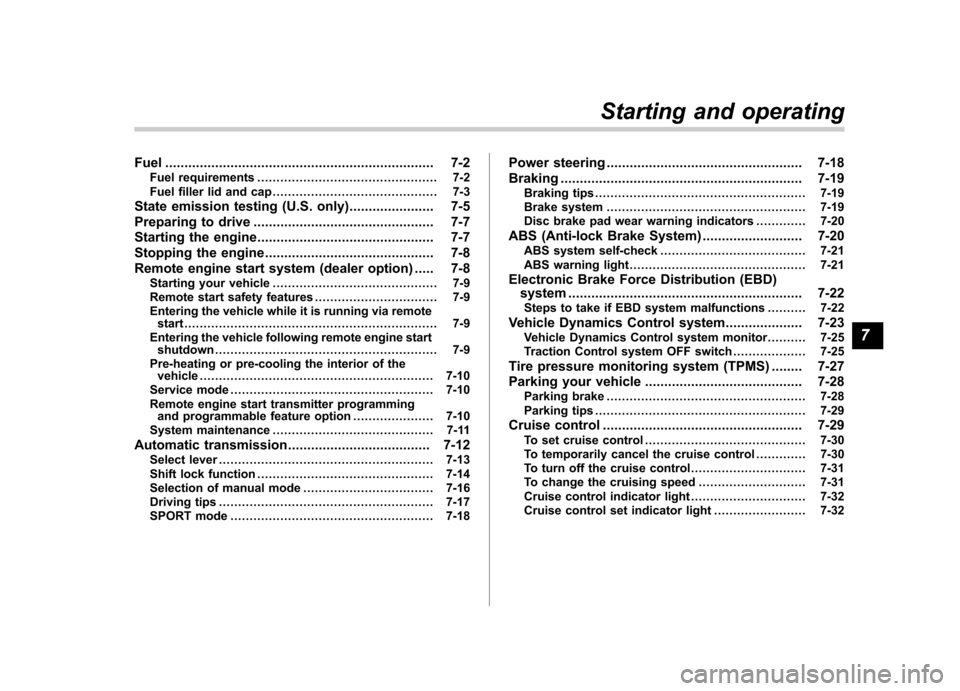
are also illuminated. Turn signal lever
To activate the right turn signal, push the
turn signal lever up. To activate the left
turn signal, push the turn signal lever
down. When the turn is finished, the lever
will return automatically. If the lever does
not return after cornering, return the lever
to the neutral position by hand.
To signal a lane change, push the turn
signal lever up or down slightly and hold it
during the lane change. The turn signal
indicator lights will flash in the direction of
the turn or lane change. The lever will
return automatically to the neutral position
when you release it.Illumination brightness con- trol
When the light switch is in the
“OFF ”
position, you can adjust the brightness of
the instrument panel illumination for better
visibility.
The brightness of audio, air conditioner,
multi-function display (if equipped) and
instrument panel illumination automati-
cally dims when the light switch is in the“
” or “”position. You can adjust
brightness of the illumination for better
visibility.
To brighten, turn the control dial upward.
To darken, turn the control dial downward. Instruments and controls
3-29
– CONTINUED –
Page 218 of 420

Rear Seat Entertainment
(RSE) system operation (ifequipped)
If your vehicle is equipped with the Rear
Seat Entertainment (RSE) system, you
can listen to the audio via the vehicle
speakers. Push the“RSE AUX ”button to
play a DVD using the Rear Seat Entertain-
ment system.
For detailed operating procedures, refer to
the Owner ’s Manual supplement for the
Rear Seat Entertainment (RSE) system.
NOTE . To watch a DVD in the front seats
using the monitor of the navigation
system, park the vehicle in a safe
location and apply the parking brake.
Images of the DVD will not be displayed
on the front monitor unless the parking
brake is applied.. The harman/kardon
®audio system
is a stereo system with 2 channels. If a
harman/kardon
®audio system is
equipped, the Rear Seat Entertainment
(RSE) system may not generate a
satisfying realistic sound when playing
5.1 channel audio sources. Precautions to observe when
handling a compact disc
Use only compact discs (CDs, CD-Rs and
CD-RWs) that have the mark shown in the
following illustration. Also, some compact
discs cannot be played.
Audio
5-29
– CONTINUED –
Page 230 of 420

especially metal ones such as
coins or aluminum foil, into the
accessory power outlet. That
could cause a short circuit. Al-
ways put the cap on the acces-
sory power outlet when it is not
in use.
. Use only electrical appliances
which are designed for 12V DC.
The maximum power rating of an
appliance that can be connected
is shown in the following list. Do
not use an appliance which ex-
ceeds the indicated wattage for
each outlet. – The two outlets in the center
console: 120W or less (When
using appliances connected
to two outlets simultaneously,
the total power consumed by
them must not exceed 120W.)
– The two outlets in the rear
cabin: 120W or less (When
using appliances connected
to two outlets simultaneously,
the total power consumed by
them must not exceed 120W.)
Overloading the accessory
power outlet can cause a short
circuit. Do not use dual adapters
or more than one electrical appli- ance.
. If the plug on your electric appli-
ance is either too loose or too
tight for the accessory power
outlet, this can result in a poor
contact or cause the plug to get
stuck. Only use plugs that fit
properly.
. Use of an electric appliance in the
accessory power outlet for a long
period of time while the engine is
not running can cause batterydischarge.
. Before driving your vehicle, make
sure that the plug and the cord
on your electrical appliance will
not interfere with your shifting
gears and operating the accel-
erator and brake pedals. If they
do, do not use the electrical
appliance while driving.
NOTE
It is possible, when using the outlet in
the center console (lower compart-
ment) with the lid closed, to pass the
electrical appliance ’s cord through a
gap between the center console (lower Interior equipment
6-11
– CONTINUED –
Page 246 of 420

Fuel...................................................................... 7-2
Fuel requirements ............................................... 7-2
Fuel filler lid and cap ........................................... 7-3
State emission testing (U.S. only) ...................... 7-5
Preparing to drive ............................................... 7-7
Starting the engine .............................................. 7-7
Stopping the engine ............................................ 7-8
Remote engine start system (dealer option) ..... 7-8
Starting your vehicle ........................................... 7-9
Remote start safety features ................................ 7-9
Entering the vehicle while it is running via remote start .................................................................. 7-9
Entering the vehicle following remote engine start shutdown .......................................................... 7-9
Pre-heating or pre-cooling the interior of the vehicle ............................................................. 7-10
Service mode ..................................................... 7-10
Remote engine start transmitter programming and programmable feature option ..................... 7-10
System maintenance .......................................... 7-11
Automatic transmission ..................................... 7-12
Select lever ........................................................ 7-13
Shift lock function .............................................. 7-14
Selection of manual mode .................................. 7-16
Driving tips ........................................................ 7-17
SPORT mode ..................................................... 7-18 Power steering
................................................... 7-18
Braking ............................................................... 7-19
Braking tips ....................................................... 7-19
Brake system .................................................... 7-19
Disc brake pad wear warning indicators ............. 7-20
ABS (Anti-lock Brake System) .......................... 7-20
ABS system self-check ...................................... 7-21
ABS warning light .............................................. 7-21
Electronic Brake Force Distribution (EBD) system ............................................................. 7-22
Steps to take if EBD system malfunctions ..... ..... 7-22
Vehicle Dynamics Control system .................... 7-23
Vehicle Dynamics Control system monitor..... ..... 7-25
Traction Control system OFF switch ................... 7-25
Tire pressure monitoring system (TPMS) ........ 7-27
Parking your vehicle ......................................... 7-28
Parking brake .................................................... 7-28
Parking tips ....................................................... 7-29
Cruise control .................................................... 7-29
To set cruise control .......................................... 7-30
To temporarily cancel the cruise control ............. 7-30
To turn off the cruise control .............................. 7-31
To change the cruising speed .. .......................... 7-31
Cruise control indicator light .............................. 7-32
Cruise control set indicator light ........................ 7-32
Starting and operating
7
Page 252 of 420

Preparing to drive
You should perform the following checks
and adjustments every day before you
start driving.
1. Check that all windows, mirrors, and
lights are clean and unobstructed.
2. Check the appearance and condition
of the tires. Also check tires for properinflation.
3. Look under the vehicle for any sign of leaks.
4. Check that the hood and rear gate are
fully closed.
5. Check the adjustment of the seat.
6. Check the adjustment of the inside
and outside mirrors.
7. Fasten your seatbelt. Check that your
passengers have fastened their seatbelts.
8. Check the operation of the warning
and indicator lights when the ignition
switch is turned to the“ON ”position.
9. Check the gauges, indicator and warn-
ing lights after starting the engine.
NOTE
Engine oil, engine coolant, brake fluid,
washer fluid and other fluid levels
should be checked daily, weekly or at
fuel stops. Starting the engine
CAUTION
. Do not operate the starter motor
continuously for more than 10
seconds. If the engine fails to
start after operating the starter
for 5 to 10 seconds, wait for 10
seconds or more before tryingagain.
. If you restart the engine while the
vehicle is moving, shift the select
lever into the “N ” position. Do
not attempt to place the select
lever of a moving vehicle into the“ P ” position.
1. Apply the parking brake.
2. Turn off unnecessary lights and ac- cessories.
3. Shift the select lever to the “P ” or “N ”
position (preferably “P ” position). The
starter will only operate when the select
lever is at the “P ”or “N ”position.
4. Turn the ignition switch to the “ON ”
position and check the operation of the
warning and indicator lights. Refer to“ Warning and indicator lights ”F 3-9.
5. Turn the ignition switch to the “START ”
position without depressing the accelera- tor pedal. Release the key immediately
after the engine has started.
If the engine does not start, try the following.
(1) Turn the ignition switch to the“LOCK ”position and wait for at least
10 seconds. After checking that the
parking brake is firmly set, turn the
ignition switch to the “START ”position
while depressing the accelerator pedal
slightly (approximately a quarter of the
full stroke). Release the accelerator
pedal as soon as the engine starts.
(2) If this fails to start the engine, turn
the ignition switch back to the “LOCK ”
position and wait for at least 10
seconds. Then fully depress the accel-
erator pedal and turn the ignition
switch to the “START ”position. If the
engine starts, quickly release the
accelerator pedal.
(3) If this fails to start the engine, turn
the ignition switch again to the “LOCK ”
position. After waiting for 10 seconds
or longer, turn the ignition switch to the“ START ”position without depressing
the accelerator pedal.
(4) If the engine still refuses to start,
contact your nearest SUBARU dealer
for assistance.
6. Confirm that all warning and indicator
lights have turned off after the engine has Starting and operating
7-7
– CONTINUED –
Page 253 of 420

7-8Starting and operating
started. The fuel injection system auto-
matically lowers the idle speed as the
engine warms up.
While the engine is warming up, make
sure that the select lever is at the “P ” or
“ N ”position and that the parking brake is
applied. NOTE . The engine may be difficult to start
when the battery has been discon-
nected and reconnected (for mainte-
nance or other purposes). This diffi-
culty is caused by the electronically
controlled throttle ’s self-diagnosis
function. To overcome it, keep the
ignition switch in the “ON ”position
for approximately 10 seconds before
starting the engine.. To protect the engine while the
select lever is in the “P ” or “N ”
position, the engine is controlled so
that the engine speed may not become
too high even if the accelerator pedal is
depressed hard. Stopping the engine
WARNING
Do not stop the engine when the
vehicle is moving. This will cause
loss of power to the power steering
and the brake booster, making steer-
ing and braking more difficult. It
could also result in accidental acti-
vation of the “LOCK ”position on the
ignition switch, causing the steering
wheel to lock.
The ignition switch should be turned off
only when the vehicle is stopped and the
engine is idling. Remote engine start system
(dealer option)
WARNING
. Do not start the engine using the
remote start system in an en-
closed environment (e.g. closed
garage). Prolonged operation of
a motor vehicle in an enclosed
environment can cause a harmful
build-up of Carbon Monoxide.
Carbon Monoxide is harmful to
your health. Exposure to high
levels of Carbon Monoxide can
cause headaches, dizziness or in
extreme cases unconsciousness
and/or death.
. Before performing any servicing
of the vehicle, temporarily place
the remote engine start system in
service mode to prevent the
system from unexpectedly start-
ing the engine.
Page 254 of 420

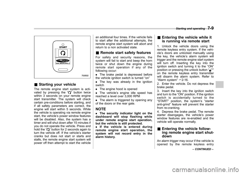
&Starting your vehicle
The remote engine start system is acti-
vated by pressing the “
”button twice
within 3 seconds on your remote engine
start transmitter. The system will check
certain pre-conditions before starting, and
if all safety parameters are correct, the
engine will start within 5 seconds. While
the vehicle is operating via remote engine
start, the vehicle ’s power window features
will be disabled. Also, the system has a
timer and will shut down after 15 minutes if
you do not operate the vehicle. Press and
hold the “
”button for 2 seconds again to
turn the vehicle off. If the vehicle ’s starter
cranks but does not start or starts and
stalls, the remote engine start system will
power off then attempt to start the vehicle an additional four times. If the vehicle fails
to start after the additional attempts, the
remote engine start system will abort and
return to a non activated state.
& Remote start safety features
For safety and security reasons, the
system will fail to start and beep the horn
twice or shut down the engine during
remote start operation if any of the
following occur: . The brake pedal is depressed before
the vehicle ignition switch is turned “on ”
. The key was already in the ignition
switch. The engine hood is opened
. The vehicle ’s engine idle speed has
reached a level over 3,000 RPM. The alarm is triggered by opening any
of the doors or the rear gate.
NOTE . The security indicator light on the
dashboard will stop flashing while
under remote engine start operation,
but the vehicle is still protected.. If the vehicle is entered during
remote engine start operation, the
system will not record entry in the
alarm history. &
Entering the vehicle while it
is running via remote start
1. Unlock the vehicle doors using the
remote keyless entry system. If the vehi-cle ’s doors are unlocked manually using
the key, the vehicle ’s alarm system will
trigger and the remote engine start system
will turn off. Inserting the key into the
ignition switch and turning it to the “ON ”
position or pressing the unlock button “
”
on the remote keyless entry transmitter
will disarm the alarm system. Refer to“ Alarm system ”F 2-16.
2. Enter the vehicle. Do not depress the
brake pedal.
3. Insert the key into the ignition switch
and turn to the “ON ”position. If the ignition
switch is accidentally turned to the“ START ”position, the system ’s “starter
anti-grind ”feature will prevent the starter
from re-cranking.
4. Depress the brake pedal. The remote
starter disengages, the vehicle ’s power
window features are re-enabled and the
vehicle will operate normally.
& Entering the vehicle follow-
ing remote engine start shut-down
An alarm trigger may occur if the vehicle is
opened by the remote keyless entry Starting and operating
7-9
– CONTINUED –