2012 SUBARU OUTBACK trailer
[x] Cancel search: trailerPage 131 of 474

3-12Instruments and controls
indicators illuminates depending on the
status of the front passenger ’s SRS frontal
airbag determined by the SUBARU ad-
vanced frontal airbag system monitoring.
If the front passenger ’s SRS frontal airbag
is activated, the passenger ’s frontal airbag
ON indicator will illuminate while the OFF
indicator will remain off.
If the front passenger ’s SRS frontal airbag
is deactivated, the passenger ’s frontal
airbag ON indicator will remain off while
the OFF indicator will illuminate.
With the ignition switch turned to the “ON ”
position, if both the ON and OFF indica-
tors remain illuminated or off simulta-
neously even after the system check
period, the system is malfunctioning.
Contact your SUBARU dealer immedi-
ately for an inspection.
& CHECK ENGINE warn-
ing light/Malfunction
indicator light
CAUTION
If the CHECK ENGINE warning light/
malfunction indicator light illumi-
nates while you are driving, have
your vehicle checked/repaired by
your SUBARU dealer as soon as
possible. Continued vehicle opera- tion without having the emission
control system checked and re-
paired as necessary could cause
serious damage, which may not be
covered by your vehicle
’s warranty.
If this light illuminates steadily or blinks
while the engine is running, it may indicate
that there is a problem or potential
problem somewhere in the emission con-
trol system. ! If the light illuminates constantly
If the light illuminates constantly while
driving or does not turn off after the engine
starts, an emission control system mal-
function has been detected.
You should have your vehicle checked by
an authorized SUBARU dealer immedi-
ately.
NOTE
This light also illuminates when the fuel
filler cap is not tightened until it clicks.
If you have recently refueled your vehicle,
the cause of the CHECK ENGINE warning
light/malfunction indicator light coming on
could be a loose or missing fuel filler cap.
Remove the cap and retighten it until it
clicks. Make sure nothing is interfering
with the sealing of the cap. Tightening the
cap will not make the CHECK ENGINE warning light/malfunction indicator light
turn off immediately. It may take several
driving trips. If the light does not turn off,
take your vehicle to your authorized
SUBARU dealer immediately. !
If the light is blinking
If the light is blinking while driving, an
engine misfire condition has been de-
tected which may damage the emission
control system.
To prevent serious damage to the emis-
sion control system, you should conform
to the following instructions. . Reduce vehicle speed.
. Avoid hard acceleration.
. Avoid steep uphill grades.
. Reduce the amount of cargo, if possi-
ble.. Stop towing a trailer as soon as
possible.
The CHECK ENGINE warning light/mal-
function indicator light may stop blinking
and illuminate steadily after several driv-
ing trips. You should have your vehicle
checked by an authorized SUBARU deal-
er immediately.
Page 304 of 474
that full vehicle control will be
maintained at all times and under
all conditions, its activation
should be seen as a sign that
the speed of the vehicle should
be reduced considerably.
. Whenever suspension compo-
nents, steering components, or
an axle are removed from a
vehicle equipped with the Vehicle
Dynamics Control system, have
an inspection of that system
performedbyanauthorized
SUBARU dealer.
. The following precautions should
be observed in order to ensure
that the Vehicle Dynamics Con-
trol system is operating properly. – All four wheels should be
fitted with tires of the same
size, type, and brand. Further-
more, the amount of wear
should be the same for all
four tires.
– Keep the tire pressure at the
proper level as shown on the
vehicle placard attached to
the driver ’s side door pillar.
– Use only the specified tem-
porary spare tire to replace a
flat tire. With a temporary spare tire, the effectiveness of
the Vehicle Dynamics Control
system is reduced and this
should be taken into account
when driving the vehicle in
such a condition.
. If non-matching tires are used,
the Vehicle Dynamics Control
system may not operate cor-
rectly.
In the event of wheelspin and/or skidding
on a slippery road surface and/or during
cornering and/or an evasive maneuver,
the Vehicle Dynamics Control system
adjusts the engine ’s output and the
wheels ’respective braking forces to help
maintain traction and directional control. . Traction Control Function
The traction control function is designed to
prevent spinning of the driving wheels on
slippery road surfaces, thereby helping to
maintain traction and directional control.
Activation of this function is indicated by
flashing of the Vehicle Dynamics Control
operation indicator light. . Skid Suppression Function
The skid suppression function is designed
to help maintain directional stability by
suppressing the wheels ’tendency to slide
sideways during steering operations. Acti- vation of this function is indicated by
flashing of the Vehicle Dynamics Control
operation indicator light.
NOTE . The Vehicle Dynamics Control sys-
tem may be considered normal when
the following conditions occur.
–Slight twitching of the brake
pedal is felt. – The vehicle or steering wheel
shakes to a small degree.– An operating sound from the
engine compartment is heard
briefly when starting the engine
and when driving off after starting
the engine. – The brake pedal seems to jolt
when driving off after starting the engine.
. In the following circumstances, the
vehicle may be less stable than it feels
to the driver. The Vehicle Dynamics
Control System may therefore operate.
Such operation does not indicate a
system malfunction.
–on gravel-covered or rutted
roads – on unfinished roads
– when the vehicle is towing a
trailer– when the vehicle is fitted with Starting and operating
7-27
– CONTINUED –
Page 310 of 474
the brake system warning light has
illuminated. Otherwise, the Hill
Holder function may not operate
properly and an accident may occur.
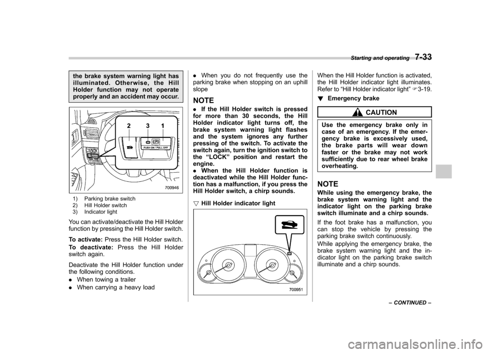
1) Parking brake switch
2) Hill Holder switch
3) Indicator light
You can activate/deactivate the Hill Holder
function by pressing the Hill Holder switch.
To activate: Press the Hill Holder switch.
To deactivate: Press the Hill Holder
switch again.
Deactivate the Hill Holder function under
the following conditions. . When towing a trailer
. When carrying a heavy load .
When you do not frequently use the
parking brake when stopping on an uphill slope NOTE . If the Hill Holder switch is pressed
for more than 30 seconds, the Hill
Holder indicator light turns off, the
brake system warning light flashes
and the system ignores any further
pressing of the switch. To activate the
switch again, turn the ignition switch tothe “LOCK ”position and restart the
engine.. When the Hill Holder function is
deactivated while the Hill Holder func-
tion has a malfunction, if you press the
Hill Holder switch, a chirp sounds. ! Hill Holder indicator light
When the Hill Holder function is activated,
the Hill Holder indicator light illuminates.
Refer to “Hill Holder indicator light ”F 3-19.
! Emergency brake
CAUTION
Use the emergency brake only in
case of an emergency. If the emer-
gency brake is excessively used,
the brake parts will wear down
faster or the brake may not work
sufficiently due to rear wheel brakeoverheating.
NOTE
While using the emergency brake, the
brake system warning light and the
indicator light on the parking brake
switch illuminate and a chirp sounds.
If the foot brake has a malfunction, you
canstopthevehiclebypressingthe
parking brake switch continuously.
While applying the emergency brake, the
brake system warning light and the in-
dicator light on the parking brake switch
illuminate and a chirp sounds. Starting and operating
7-33
– CONTINUED –
Page 312 of 474
Cruise control
Cruise control enables you to maintain a
constant vehicle speed without holding
your foot on the accelerator pedal and it is
operative when the vehicle speed is 25
mph (40 km/h) or more.
WARNING
Do not use the cruise control under
any of the following conditions.
These may cause loss of vehiclecontrol. . driving up or down a steep grade
. driving on slippery or winding
roads
. driving in heavy traffic
. towing a trailer
NOTE . If you press the “CRUISE ”main
switch button while turning the ignition switch “ON ”, the cruise control func-
tion is deactivated and the cruise
control indicator light flashes. To re-
activate the cruise control function,
turn the ignition switch back to the“ Acc ”or “LOCK ”position, and then
turn it again to the “ON ”position.
. Make sure the “CRUISE ”main switch is turned off when the cruise
control is not in use to avoid uninten-
tionally setting of the cruise control. &
To set cruise control
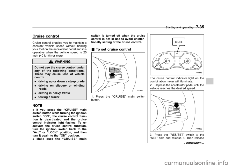
1. Press the “CRUISE ”main switch
button.
The cruise control indicator light on the
combination meter will illuminate.
2. Depress the accelerator pedal until the
vehicle reaches the desired speed.
3. Press the “RES/SET ”switch to the
“ SET ”side and release it. Then release Starting and operating
7-35
– CONTINUED –
Page 316 of 474
New vehicle break-in driving–the first
1,000 miles (1,600 km) ..................................... 8-2
Fuel economy hints ............................................ 8-2
Engine exhaust gas (carbon monoxide) ............ 8-2
Catalytic converter .............................................. 8-3
Periodic inspections ........................................... 8-4
Driving in foreign countries ............................... 8-4
Driving tips for AWD vehicles ............................ 8-5
Off road driving ................................................... 8-6
Legacy ................................................................ 8-6
Outback .............................................................. 8-6
Winter driving ...................................................... 8-8
Operation during cold weather ............................. 8-8
Driving on snowy and icy roads ......................... 8-10
Corrosion protection .......................................... 8-11
Snow tires ......................................................... 8-11
Tire chains ......................................................... 8-12 Rocking the vehicle
........................................... 8-12
Loading your vehicle ......................................... 8-12
Vehicle capacity weight ...................................... 8-13
GVWR and GAWR (Gross Vehicle Weight Rating and Gross Axle Weight Rating) ........................ 8-14
Roof rails with integrated crossbars (Outback) ........................................................ 8-14
Trailer hitch (Outback —if equipped) .............. 8-17
Connecting a trailer ........................................... 8-18
When you do not tow a trailer .. .......................... 8-19
Trailer towing ..................................................... 8-19
Warranties and maintenance .............................. 8-19
Maximum load limits .......................................... 8-20
Trailer hitches .................................................... 8-23
Connecting a trailer ........................................... 8-24
Trailer towing tips .............................................. 8-25Driving tips
8
Page 329 of 474
8-14Driving tips
side door pillar. It includes the total weight
of the driver and all passengers and their
belongings, any optional equipment such
as a trailer hitch, roof rack or bike carrier,
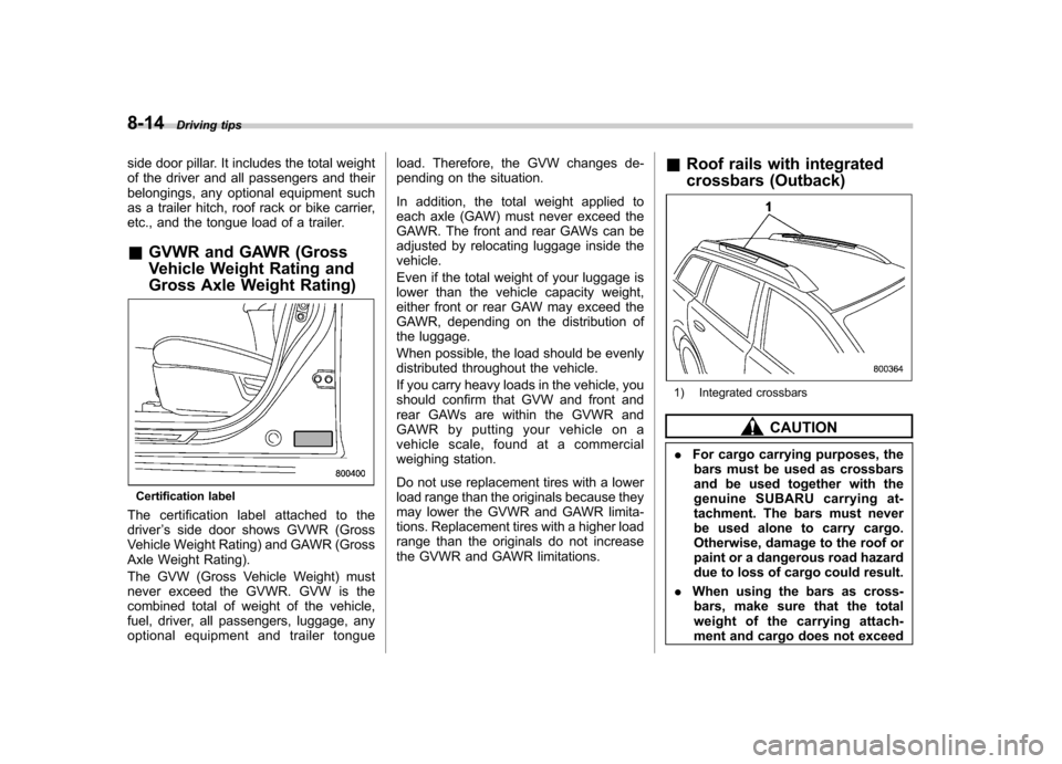
etc., and the tongue load of a trailer. &GVWR and GAWR (Gross
Vehicle Weight Rating and
Gross Axle Weight Rating)
Certification label
The certification label attached to the driver ’s side door shows GVWR (Gross
Vehicle Weight Rating) and GAWR (Gross
Axle Weight Rating).
The GVW (Gross Vehicle Weight) must
never exceed the GVWR. GVW is the
combined total of weight of the vehicle,
fuel, driver, all passengers, luggage, any
optional equipment and trailer tongue load. Therefore, the GVW changes de-
pending on the situation.
In addition, the total weight applied to
each axle (GAW) must never exceed the
GAWR. The front and rear GAWs can be
adjusted by relocating luggage inside the vehicle.
Even if the total weight of your luggage is
lower than the vehicle capacity weight,
either front or rear GAW may exceed the
GAWR, depending on the distribution of
the luggage.
When possible, the load should be evenly
distributed throughout the vehicle.
If you carry heavy loads in the vehicle, you
should confirm that GVW and front and
rear GAWs are within the GVWR and
GAWR by putting your vehicle on a
vehicle scale, found at a commercial
weighing station.
Do not use replacement tires with a lower
load range than the originals because they
may lower the GVWR and GAWR limita-
tions. Replacement tires with a higher load
range than the originals do not increase
the GVWR and GAWR limitations.
&
Roof rails with integrated
crossbars (Outback)
1) Integrated crossbars
CAUTION
. For cargo carrying purposes, the
bars must be used as crossbars
and be used together with the
genuine SUBARU carrying at-
tachment. The bars must never
be used alone to carry cargo.
Otherwise, damage to the roof or
paint or a dangerous road hazard
due to loss of cargo could result.
. When using the bars as cross-
bars, make sure that the total
weight of the carrying attach-
ment and cargo does not exceed
Page 332 of 474
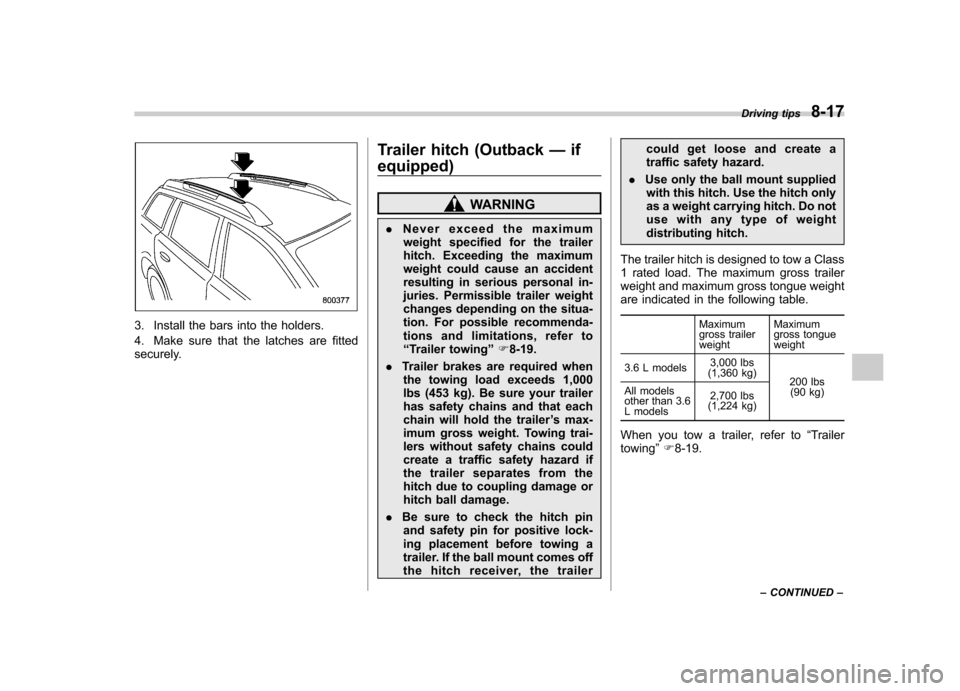
3. Install the bars into the holders.
4. Make sure that the latches are fitted
securely.Trailer hitch (Outback
—if
equipped)
WARNING
. Never exceed the maximum
weight specified for the trailer
hitch. Exceeding the maximum
weight could cause an accident
resulting in serious personal in-
juries. Permissible trailer weight
changes depending on the situa-
tion. For possible recommenda-
tions and limitations, refer to“ Trailer towing ”F 8-19.
. Trailer brakes are required when
the towing load exceeds 1,000
lbs (453 kg). Be sure your trailer
has safety chains and that each
chain will hold the trailer ’s max-
imum gross weight. Towing trai-
lers without safety chains could
create a traffic safety hazard if
the trailer separates from the
hitch due to coupling damage or
hitch ball damage.
. Be sure to check the hitch pin
and safety pin for positive lock-
ing placement before towing a
trailer. If the ball mount comes off
the hitch receiver, the trailer could get loose and create a
traffic safety hazard.
. Use only the ball mount supplied
with this hitch. Use the hitch only
as a weight carrying hitch. Do not
use with any type of weight
distributing hitch.
The trailer hitch is designed to tow a Class
1 rated load. The maximum gross trailer
weight and maximum gross tongue weight
are indicated in the following table. Maximum
gross trailerweightMaximum
gross tongueweight
3.6 L models 3,000 lbs
(1,360 kg) 200 lbs
(90 kg)
All models
other than 3.6
L models 2,700 lbs
(1,224 kg)
When you tow a trailer, refer to “Trailer
towing ”F 8-19. Driving tips
8-17
– CONTINUED –
Page 333 of 474

8-18Driving tips
&Connecting a trailer
1. Remove the receiver cover from the
hitch receiver tube. Then insert the ball
mount into the hitch receiver tube.
2. Insert the hitch pin into the hole on the
hitch receiver tube so that the pin passes
through the ball mount.
3. Insert the safety pin onto the hitch pin
securely.
4. Pull the ball mount to make sure it
does not come off the hitch receiver.
1) Hitch ball installation point
2) Hooks for safety chains 5. Use only a hitch ball that is appropriate
for the ball mount and your trailer. The
hitch ball must be securely installed on the
ball mount.
6. Connect your trailer to the hitch ball.
7. Connect the trailer and the hitch with
safety chains that will hold the trailer
’s
maximum gross weight. The chains
should cross under the trailer tongue to
prevent the tongue from dropping onto the
ground in case it should disconnect from
the hitch ball. Allow sufficient slack in the
chains taking tight turn situations into
account; however, be careful not to let
them drag on the ground.
WARNING
Do not connect safety chains to part
of the vehicle other than the safety
chain hooks.