2012 SUBARU OUTBACK rear view mirror
[x] Cancel search: rear view mirrorPage 61 of 474
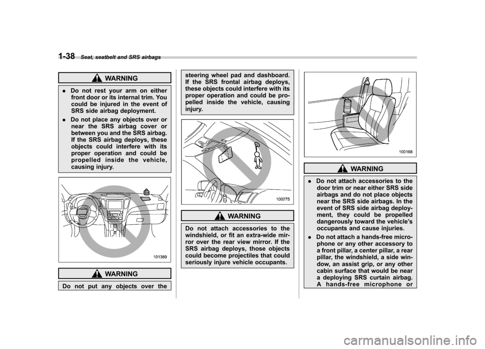
1-38Seat, seatbelt and SRS airbags
WARNING
. Do not rest your arm on either
front door or its internal trim. You
could be injured in the event of
SRS side airbag deployment.
. Do not place any objects over or
near the SRS airbag cover or
between you and the SRS airbag.
If the SRS airbag deploys, these
objects could interfere with its
proper operation and could be
propelled inside the vehicle,
causing injury.
WARNING
Do not put any objects over the steering wheel pad and dashboard.
If the SRS frontal airbag deploys,
these objects could interfere with its
proper operation and could be pro-
pelled inside the vehicle, causing
injury.
WARNING
Do not attach accessories to the
windshield, or fit an extra-wide mir-
ror over the rear view mirror. If the
SRS airbag deploys, those objects
could become projectiles that could
seriously injure vehicle occupants.
WARNING
. Do not attach accessories to the
door trim or near either SRS side
airbags and do not place objects
near the SRS side airbags. In the
event of SRS side airbag deploy-
ment, they could be propelled
dangerously toward the vehicle ’s
occupants and cause injuries.
. Do not attach a hands-free micro-
phone or any other accessory to
a front pillar, a center pillar, a rear
pillar, the windshield, a side win-
dow, an assist grip, or any other
cabin surface that would be near
a deploying SRS curtain airbag.
A hands-free microphone or
Page 155 of 474

3-36Instruments and controls
&Type B inside mirror (if equipped)
1) Electronic compass display
2) Rear view image display
3) HomeLink
®button 1
4) HomeLink®button 2
5) Function indicator
6) HomeLink
®button 3
7) Photosensor
8) Power button
9) Compass button
The mirror has the following features. . Auto-dimming function for anti-glare
capability. Rear view image display
. Electronic compass display
. HomeLink
®Wireless Control System
Using the power button and compass button, you can display the various func-
tions of the rear view image display and
the electronic compass display based on
how long you press the buttons.
Power button
Gear
position Period of
time button
is pressed Function
displayed
Except
R (reverse) Briefly
Auto-dimming
function ON/OFF*
R (reverse) Briefly Rear view image
display: ON/OFF* mode
6to12 seconds Enter the lan-
guage selection mode
12 to 15 seconds Rear view image
display: opera-
tional/non-opera-
tional mode
*: The setting returns to “ON ”as a default
setting every time the ignition switch is turned to the “OFF ”position. Compass button
Gear
position Period of
time button is pressed Function
displayed
Except
R (reverse) Briefly
Electronic com-
pass display ON/ OFF
3to6
seconds Enter the com-
pass zone setting mode
6to9
seconds Enter the com-
pass calibration mode
! Auto-dimming function
The auto-dimming function is an anti-glare
capability which automatically reduces
glare coming from headlights of vehicles
behind you.
By pressing the power button, the auto-
dimming function is toggled on or off.
When the auto-dimming function is on, the
function indicator will illuminate in green.
Even with the mirror in anti-glare mode,
the mirror surface turns bright if the
transmission is shifted into the “R ” (re-
verse) position. This is to ensure good
rearward visibility during reversing.
Page 156 of 474

The mirror has a photosensor attached on
both the front and back sides. During
nighttime driving, these sensors detect
distracting glare from vehicle headlights
behind you and automatically dim the
mirror to eliminate glare and preserve
your vision. For this reason, use care not
to cover the sensors with stickers, or other
similar items. Periodically wipe the sen-
sors clean using a piece of dry soft cotton
cloth or an applicator. NOTE
When cleaning the mirror, use a paper
towel or similar item dampened with
glass cleaner. Do not spray glass
cleaner directly on the mirror surface.
By doing so, the sprayed glass cleaner
could enter the inside of the mirrorhousing. That may cause a malfunction
in the mirror. !
Rear view image display
When the ignition switch is in the “ON ”
position and the transmission is in the “R ”
(reverse) position, the rear view camera
automatically displays the rear view image
behind the vehicle on the inside mirror.
Also, the following help lines are indicated
as a guide to help you realize the actual
distance from the display.1) Vehicle width line (oblique vertical line)
2) Approx. 10 feet (3 m) from the bumper (green horizontal line)
3) Approx. 6.5 feet (2 m) from the bumper (green horizontal line)
4) Approx. 3 feet (1 m) from the bumper (yellow horizontal line)
5) Approx. 1.5 feet (0.5 m) from the bumper (red horizontal line)
By pressing the power button while the
transmission is in the “R ” (reverse) posi-
tion, the rear view image display toggles to
the on or off mode.
Once the rear view image display is set to
the off mode, the display stays in the off
mode, with the function indicator in or-
ange, every time the transmission is
shifted into the “R ”(reverse) position.
Instruments and controls
3-37
– CONTINUED –
Page 157 of 474

3-38Instruments and controls
If the ignition switch is turned to the “OFF ”
position, the display setting returns to the
on mode as a default setting the next time
the ignition switch is turned to the “ON ”
position. ! Language mode change
The language mode of the captions on the
rear view image display is selectable in
English or French in the following ways.
1. Press and hold the power button for 6
to 12 seconds while the transmission is inthe “R ” (reverse) position, and then
release it. The display will enter the
language selection mode.
2. Briefly press the power button to
toggle the captions on the display in
English or French.
3. By releasing the power button for 5
seconds, the display blinks one time to
show that the language mode is selected. ! Non-operational mode
The rear view image display can be set as
non-operational. After setting the display
to the non-operational mode, the display
does not show the rear view image even if
the ignition switch is reset (turning the
ignition switch to the “ON ”position after
turning it to the “OFF ”position).
To set the display to the non-operational mode, press and hold the power button for
12 to 15 seconds while the transmission is
in the
“R ” (reverse) position, and then
release it. The display is now in the non-
operational mode. After the display has
been set to the non-operational mode, the
function indicator will illuminate in orange
whilethetransmissionisinthe “R ”
(reverse) position.
To return the display to the operational
mode, press and hold the power button for
12 to 15 seconds again.
For precautions about the rear view
camera and the rear view image, refer to“ Rear view camera ”F 6-19.
! Electronic compass display
By briefly pressing the compass button,
the compass display is toggled on or off.
When the compass display is on, an
illuminated compass reading will appear
on the mirror.
Using the electronic compass properly,
the following compass zone adjustment
and compass calibration will be neces-
sary. !
Compass zone adjustment
Compass calibration zones
1. Refer to the “Compass calibration
zones ”map shown above to verify that
the compass zone setting is correct for
your geographical location.
2. Press and hold the compass button for
3 to 6 seconds, and then release it. The
zone number will be shown on the
electronic compass display.
3. Press the compass button repeatedly
until the correct zone number for your
location is displayed.
4. Releasing the button for 3 seconds will
exit the zone setting mode.
Page 254 of 474
Interior light......................................................... 6-2
Dome light .......................................................... 6-2
Map light ............................................................. 6-2
Cargo area light (Outback) ................................... 6-3
Sun visors ........................................................... 6-4
Sun visor extension plate .................................... 6-4
Vanity mirror with light ........................................ 6-5
Storage compartment ......................................... 6-5
Glove box ........................................................... 6-6
Center console box ............................................. 6-6
Overhead console ............................................... 6-8
Pocket (if equipped) ............................................ 6-8
Cup holder ........................................................... 6-8
Front passenger ’s cup holder .............................. 6-9
Rear passenger ’s cup holder ............................... 6-9
Bottle holders ...................................................... 6-9
Accessory power outlets ................................... 6-10 Ashtray (if equipped)
......................................... 6-12
Coat hook ........................................................... 6-13
Shopping bag hook ........................................... 6-13
Legacy .............................................................. 6-13
Outback ............................................................ 6-14
Floor mat ............................................................ 6-14
Cargo area cover (Outback –if equipped) ....... 6-15
Using the cover ................................................. 6-15
To remove the cover housing ... .......................... 6-16
Stowage of the cargo area cover ........................ 6-16
To install the cover housing ............................... 6-17
Convenient tie-down hooks (Outback) ............. 6-17
Under-floor storage compartment .................... 6-18
Rear view camera (if equipped) ........................ 6-19
How to use the rear view camera ....................... 6-20
Viewing range on the screen .............................. 6-21
Help line ............................................................ 6-22 Interior equipment
6
Page 258 of 474
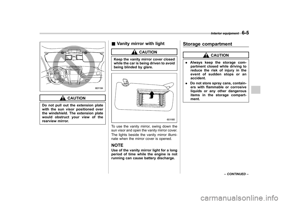
CAUTION
Do not pull out the extension plate
with the sun visor positioned over
the windshield. The extension plate
would obstruct your view of the
rearview mirror. &
Vanity mirror with light
CAUTION
Keep the vanity mirror cover closed
while the car is being driven to avoid
being blinded by glare.
To use the vanity mirror, swing down the
sun visor and open the vanity mirror cover.
The lights beside the vanity mirror illumi-
nate when the mirror cover is opened. NOTE
Use of the vanity mirror light for a long
period of time while the engine is not
running can cause battery discharge. Storage compartment
CAUTION
. Always keep the storage com-
partment closed while driving to
reduce the risk of injury in the
event of sudden stops or anaccident.
. Do not store spray cans, contain-
ers with flammable or corrosive
liquids or any other dangerous
items in the storage compart-ment. Interior equipment
6-5
– CONTINUED –
Page 272 of 474
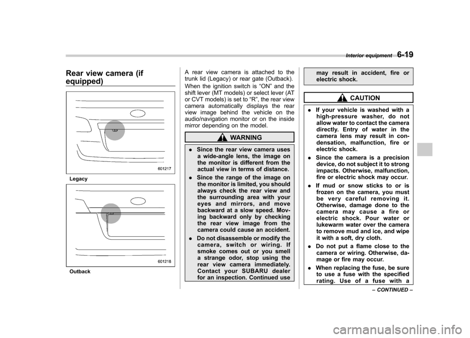
Rear view camera (if equipped)
Legacy
OutbackA rear view camera is attached to the
trunk lid (Legacy) or rear gate (Outback).
When the ignition switch is
“ON ”and the
shift lever (MT models) or select lever (AT
or CVT models) is set to “R ”, the rear view
camera automatically displays the rear
view image behind the vehicle on the
audio/navigation monitor or on the inside
mirror depending on the model.
WARNING
. Since the rear view camera uses
a wide-angle lens, the image on
the monitor is different from the
actual view in terms of distance.
. Since the range of the image on
the monitor is limited, you should
always check the rear view and
the surrounding area with your
eyes and mirrors, and move
backward at a slow speed. Mov-
ing backward only by checking
the rear view image from the
camera could cause an accident.
. Do not disassemble or modify the
camera, switch or wiring. If
smoke comes out or you smell
a strange odor, stop using the
rear view camera immediately.
Contact your SUBARU dealer
for an inspection. Continued use may result in accident, fire or
electric shock.
CAUTION
. If your vehicle is washed with a
high-pressure washer, do not
allow water to contact the camera
directly. Entry of water in the
camera lens may result in con-
densation, malfunction, fire or
electric shock.
. Since the camera is a precision
device, do not subject it to strong
impacts. Otherwise, malfunction,
fire or electric shock may occur.
. If mud or snow sticks to or is
frozen on the camera, you must
be very careful removing it.
Otherwise, damage done to the
camera may cause a fire or
electric shock. Pour water or
lukewarm water over the camera
to remove mud and ice, and wipe
it with a soft, dry cloth.
. Do not put a flame close to the
camera or wiring. Otherwise, da-
mage or fire may occur.
. When replacing the fuse, be sure
to use a fuse with the specified
rating. Use of a fuse with a Interior equipment
6-19
– CONTINUED –
Page 273 of 474
6-20Interior equipment
different rating may result in a malfunction.
. If the rear view camera is used for
a long time while the engine is
not operated, the battery may
become completely discharged.
NOTE . Do not wipe the camera with alcohol,
benzine or paint thinner. Otherwise,
discoloration may occur. To remove
contamination, wipe the camera with a
cloth moistened with a diluted neutral
detergent and then wipe it with a soft,
dry cloth.. When waxing the vehicle, be careful
not to apply the wax to the camera. If it
comes in contact with the camera,
moisten a clean cloth with a diluted
neutral detergent to remove the wax. . The camera lens has hard coating to
help prevent scratches. However, when
washing the vehicle or cleaning the
camera lens, be careful not to scratch
the camera lens. Do not use a washing
brush directly on the camera lens. The
monitor screen may be adversely af-fected.. Strong light shined on the camera
lens may develop white light stripes
around the light source. This is not a malfunction..
Under fluorescent lighting, the dis-
play may flicker. However, this is not amalfunction.. The image of the rear view camera
may be slightly different from the
actual color of the objects.
& How to use the rear view camera
When the shift lever or select lever is set to “R ”, the rear view camera automatically
displays the rear view image from the
vehicle. When the lever is set to other
positions, the image before setting to “R ”
is displayed.
1. Set the ignition switch to “ON ”.
2. Set the shift lever or select lever to “R ”.
NOTE . For models with the genuine
SUBARU navigation system, the image
of the rear view camera has priority
over other screen displays. To operate
other screens, set the shift lever (MT
models) or select lever (AT and CVT
models) to a position other than “R ”.
. The image of the rear view camera is
horizontally reversed as is the case
with the vehicle rearview mirror or the
side view mirror. .
It may be difficult to see the image of
the rearview camera in the following
cases. This is not a malfunction of thecamera.
–The vehicle is in a dark place (at
night, in a tunnel, etc.). – The vehicle is in an extremely hot
or cold place.– An object (such as raindrops,
snow, dirt, etc.) that disturbs the
view of the rear view camera sticks
to the lens of the camera. – Strong light shined directly on
the camera lens (occasionally, there
are vertical lines on the screen).