2012 SUBARU OUTBACK radiator
[x] Cancel search: radiatorPage 179 of 474
4-8Climate control
ON position is selected, the indicator light
on the air inlet selection button illuminates.
OFF position (outside air) : Outside air is
drawn into the passenger compartment.
Press the air inlet selection button to the
OFF position when the interior has cooled
to a comfortable temperature and the road
is no longer dusty. The indicator light will
turn off.
WARNING
Continued operation in the ON posi-
tion may fog up the windows. Switch
to the OFF position as soon as the
outside dusty condition clears. Defrosting
Select the desired
“
”mode or “”mode
to defrost or dehumidify the windshield
and front door windows by performing the
following procedures.
For type A: Press the airflow control button
and select the “
”mode or “”mode.
For type B: Press the airflow mode
selection button to select the “
”mode
or press the defroster button to select the “
” mode.
NOTE
When the “
”mode or “”mode is
selected, the air conditioner compres-
sor automatically operates to more
quickly defog the windshield. At the
same time, the air inlet selection is
automatically set to the outside air
mode. For details, refer to “Airflow
mode selection ”F 4-6. Operating tips for heater and
air conditioner &
Cleaning ventilator grille
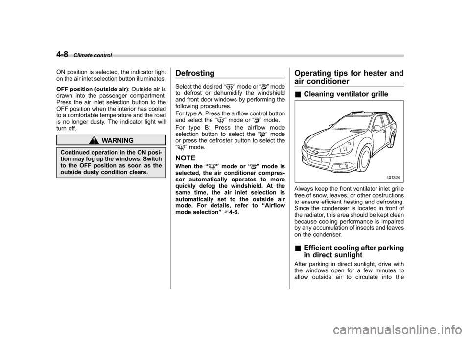
Always keep the front ventilator inlet grille
free of snow, leaves, or other obstructions
to ensure efficient heating and defrosting.
Since the condenser is located in front of
the radiator, this area should be kept clean
because cooling performance is impaired
by any accumulation of insects and leaves
on the condenser. &Efficient cooling after parking
in direct sunlight
After parking in direct sunlight, drive with
the windows open for a few minutes to
allow outside air to circulate into the
Page 233 of 474
5-50Audio
.The sound quality may degrade due
to the influence of the cell phone that is
connected to the system or the circum-
stances of the Bluetooth network. . When another Bluetooth
®device is
simultaneously connected, noise may
be heard in the voice coming from the
hands-free phone. ! Corresponding profiles for the cell phone
. HFP (Hands Free Profile): Ver. 1.0
. OPP (Object Push Profile): Ver. 1.1
& Certification for the Hands-
free system
CAUTION
FCC WARNING
Changes or modifications not ex-
pressly approved by the party re-
sponsible for compliance could void
the user ’s authority to operate the
equipment.
FCC ID: ACJ932C5ZZZ035
IC ID: 216J-C5ZZZ035
Made in Japan NOTE
This device complies with Part 15 of
the FCC Rules and Industry Canada
licence-exempt RSS standard(s). Op-
eration is subject to the following two
conditions: (1) this device may not
cause harmful interference, and (2) this
device must accept any interference,
including interference that may cause
undesired operation of this device. NOTE
This equipment has been tested and
found to comply with the limits for a
Class B digital device, pursuant to Part
15 of the FCC Rules. These limits are
designed to provide reasonable protec-
tion against harmful interference in a
residential installation. This equipment
may cause harmful interference to
radio communications, if it is not
installed and used in accordance with
the instructions. However, there is no
guarantee that interference will not
occur in a particular installation. If this
equipment does cause harmful inter-
ference to radio or television reception,
which can be determined by turning the
equipment off and on, the user is
encouraged to try to correct the inter-
ference by one or more of the followingmeasures..
Reorient or relocate the receiving
antenna.. Increase the separation between the
equipment and receiver.. Connect the equipment into an out-
let on a circuit different from that to
which the receiver is connected.. Consult the dealer or an experi-
enced radio/TV technician for help.. Changes or modifications not ex-
pressly approved by the party respon-
sible for compliance could void theuser ’s authority to operate the equip-
ment.. This equipment complies with FCC/
IC radiation exposure limits set forth
for an uncontrolled equipment and
meets the FCC radio frequency (RF)
Exposure Guidelines in Supplement C
to OET65 and RSS-102 of the IC radio
frequency (RF) Exposure rules. This
equipment has very low levels of RF
energy that it deemed to comply with-
out maximum permissive exposure
evaluation (MPE). But it is desirable
that it should be installed and operated
keeping the radiator at least 20 cm or
more away from person ’s body (ex-
cluding extremities: hands, wrists, feet
and ankles).
Page 356 of 474
Engine overheating
WARNING
Never attempt to remove the radia-
tor cap until the engine has been
shut off and has fully cooled down.
When the engine is hot, the coolant
is under pressure. Removing the
cap while the engine is still hot
could release a spray of boiling hot
coolant, which could burn you very
seriously.
If the engine overheats, pull off the road
safely and stop the vehicle in a safe place. & If steam is coming from the
engine compartment
Turn off the engine and get everyone
away from the vehicle until it cools down. & If no steam is coming from
the engine compartment
NOTE
For details about how to check the
coolant level or how to add coolant,
refer to “Engine coolant ”F 11-17.
1. Keep the engine running at idlingspeed. 2. Open the hood to ventilate the engine
compartment. Refer to
“Engine hood ”
F 11-7.
Confirm that the cooling fan is turning. If
the fan is not turning, immediately turn off
the engine and contact your authorized
dealer for repair.
3. After the engine coolant temperature
has dropped, turn off the engine.
If the coolant temperature high warning
light illuminates, turn off the engine. Referto “Coolant temperature low indicator light/
Coolant temperature high warning light ”
F 3-13.
4. After the engine has fully cooled down,
check the coolant level in the reserve tank.
If the coolant level is below the “LOW ”
mark, add coolant up to the “FULL ”mark.
5. If there is no coolant in the reserve
tank, add coolant to the reserve tank.
Then remove the radiator cap and fill the
radiator with coolant.
If you remove the radiator cap from a hot
radiator, first wrap a thick cloth around the
radiator cap, then turn the cap counter-
clockwise slowly without pressing down
until it stops. Release the pressure from
the radiator. After the pressure has been
fully released, remove the cap by pressing
down and turning it. TowingWARNING
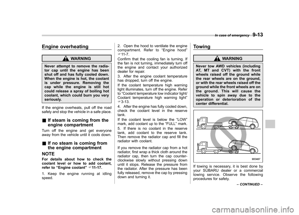
Never tow AWD vehicles (including
AT, MT and CVT) with the front
wheels raised off the ground while
the rear wheels are on the ground,
or with the rear wheels raised off the
ground while the front wheels are on
the ground. This will cause the
vehicle to spin away due to the
operation or deterioration of the
center differential.
If towing is necessary, it is best done by
your SUBARU dealer or a commercial
towing service. Observe the following
procedures for safety. In case of emergency
9-13
– CONTINUED –
Page 380 of 474
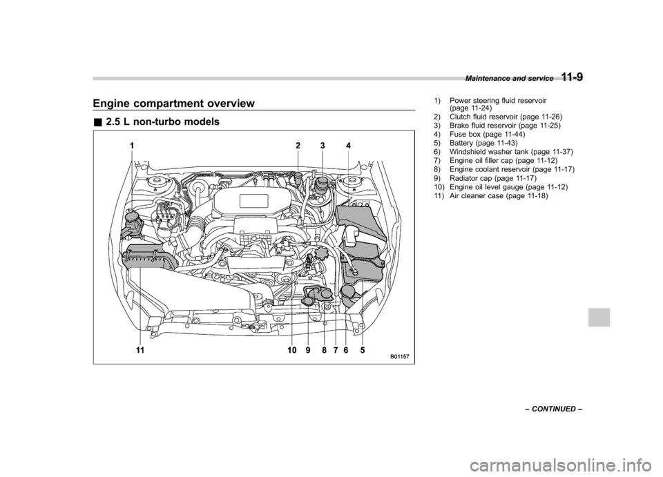
Engine compartment overview &2.5 L non-turbo models1) Power steering fluid reservoir
(page 11-24)
2) Clutch fluid reservoir (page 11-26)
3) Brake fluid reservoir (page 11-25)
4) Fuse box (page 11-44)
5) Battery (page 11-43)
6) Windshield washer tank (page 11-37)
7) Engine oil filler cap (page 11-12)
8) Engine coolant reservoir (page 11-17)
9) Radiator cap (page 11-17)
10) Engine oil level gauge (page 11-12)
11) Air cleaner case (page 11-18) Maintenance and service
11-9
– CONTINUED –
Page 381 of 474
11-10Maintenance and service
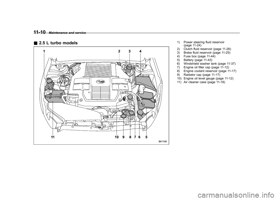
& 2.5 L turbo models
1) Power steering fluid reservoir
(page 11-24)
2) Clutch fluid reservoir (page 11-26)
3) Brake fluid reservoir (page 11-25)
4) Fuse box (page 11-44)
5) Battery (page 11-43)
6) Windshield washer tank (page 11-37)
7) Engine oil filler cap (page 11-12)
8) Engine coolant reservoir (page 11-17)
9) Radiator cap (page 11-17)
10) Engine oil level gauge (page 11-12)
11) Air cleaner case (page 11-18)
Page 382 of 474
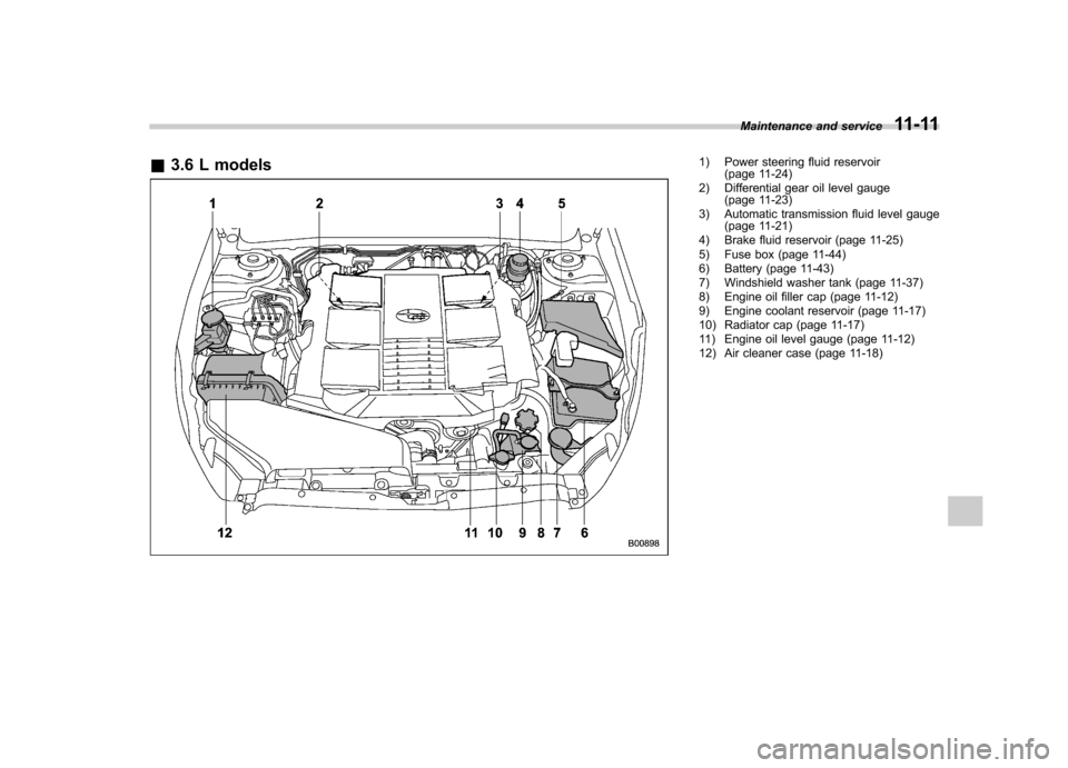
&3.6 L models1) Power steering fluid reservoir
(page 11-24)
2) Differential gear oil level gauge (page 11-23)
3) Automatic transmission fluid level gauge (page 11-21)
4) Brake fluid reservoir (page 11-25)
5) Fuse box (page 11-44)
6) Battery (page 11-43)
7) Windshield washer tank (page 11-37)
8) Engine oil filler cap (page 11-12)
9) Engine coolant reservoir (page 11-17)
10) Radiator cap (page 11-17)
11) Engine oil level gauge (page 11-12)
12) Air cleaner case (page 11-18) Maintenance and service
11-11
Page 388 of 474
shortened to that of the mixing coolant.
. Do not splash the engine coolant
over painted parts. The alcohol
contained in the engine coolant
may damage the paint surface.
& Cooling fan, hose and con- nections
Your vehicle employs an electric cooling
fan which is thermostatically controlled to
operate when the engine coolant reaches
a specific temperature.
If the radiator cooling fan does not operate
even when the coolant temperature high
warning light illuminates, the cooling fan
circuit may be defective. Check the fuse
and replace it if necessary. Refer to“ Fuses ”F 11-44 and “Fuses and circuits ”
F 12-10. If the fuse is not blown, have the
cooling system checked by your SUBARU
dealer.
If frequent addition of coolant is neces-
sary, there may be a leak in the engine
cooling system. It is recommended that
the cooling system and connections be
checked for leaks, damage, or looseness. &
Engine coolant
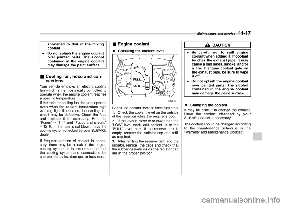
! Checking the coolant level
Check the coolant level at each fuel stop.
1. Check the coolant level on the outside
of the reservoir while the engine is cool.
2. If the level is close to or lower than the “LOW ”level mark, add coolant up to the
“ FULL ”level mark. If the reserve tank is
empty, remove the radiator cap and refill
as required.
3. After refilling the reserve tank and the
radiator, reinstall the caps and check that
the rubber gaskets inside the radiator cap
are in the proper position.
CAUTION
. Be careful not to spill engine
coolant when adding it. If coolant
touches the exhaust pipe, it may
cause a bad smell, smoke, and/or
a fire. If engine coolant gets on
the exhaust pipe, be sure to wipe
it off.
. Do not splash the engine coolant
over painted parts. The alcohol
contained in the engine coolant
may damage the paint surface.
! Changing the coolant
It may be difficult to change the coolant.
Have the coolant changed by your
SUBARU dealer if necessary.
The coolant should be changed according
to the maintenance schedule in the“ Warranty and Maintenance Booklet ”.
Maintenance and service
11-17