2012 SUBARU OUTBACK ECU
[x] Cancel search: ECUPage 251 of 474
5-68Audio
NOTE
While the phonebook is locked, if the
operation restricted menu is selected,“ PHBK LOCK ”(type B audio)/ “Phone-
book locked! ”(type C audio) is dis-
played. ! Unlocking the phonebook
1. Select the “PHBK UNLOCK ”/“ PHONE-
BOOK UNLOCK ”menu.
NOTE
If the phonebook is not locked, “UN-
LOCK ”(type B audio)/ “The phonebook
is unlocked. ”(type C audio) is dis-
played and the mode changes to the
security mode.
2. Input the PIN code by performing one
of the following procedures.
–Operate the “TUNE ”dial.
– Press the talk switch
and say
the number.
3. Select the “CONFIRM ”(type B audio)/
“ Confirm PIN? ”(type C audio) menu.
– If the inputted PIN code is correct,
“ UNLOCKED ”(type B audio)/ “The
phonebook is unlocked. ”(type C
audio) will be displayed and the
phonebook is unlocked. !
Phone setup
After selecting the “PHONE SETUP ”
menu, perform the following procedure. ! Pairing phone
Refer to “Preparation for using the Hands-
free system ”F 5-53.
! Selecting phone
To select the registered cell phone for
connecting to the in-vehicle equipment,
perform the following procedure.
1. Select the “SELECT PHONE ”menu.
– If no cell phones are registered,
“ EMPTY ”(type B audio)/ “No Phones
have been paired. ”(type C audio) is
displayed and the mode changes to the “PHONE SETUP ”mode.
2. Select the cell phone by performing
one of the following procedures. –Operate the “TUNE ”dial.
– Press the talk switch
and say
the voice tag. – Press the talk switch
and use
the list phones function (refer to “List
phones function ”F 5-69.)
3. Select the “CONFIRM ”(type B audio)/
“ Confirm Phone selection? ”(type C audio)
menu (only after saying the voice tag).
–“ SELECTED ”(type B audio)/
“ Phone is selected. ”(type C audio) is displayed, the selected cell phone is
connected to the in-vehicle equipment
and the mode changes to the
“PHONE
SETUP ”mode.
NOTE
For type B audio, if the cell phone
cannot be connected to the in-vehicleequipment, “FAILED ”is displayed and
the mode changes to the “PHONE
SETUP ”mode.
! Changing the voice tag of the cellphone
1. Select the “CHANGE NAME ”(type B
audio)/ “Change Phone Name ”(type C
audio) menu.
–If no cell phones are registered,
“ EMPTY ”(type B audio)/ “No Phones
have been paired. ”(type C audio) is
displayed and the mode changes tothe “PHONE SETUP ”mode.
2. Select the cell phone by performing
one of the following procedures. –Operate the “TUNE ”dial.
– Press the talk switch
and say
the voice tag. – Press the talk switch
and use
the list phones function (refer to “List
phones function ”F 5-69.).
3. Register the voice tag. For details,
Page 265 of 474
6-12Interior equipment
power outlet in the center console to be
used. Pass the cord of the electrical
appliance through this gap. Ashtray (if equipped)
CAUTION
. Do not use ashtrays as waste
receptacles or leave a lighted
cigarette in an ashtray. This
could cause a fire.
. Always extinguish matches and
cigarettes before putting them
into the ashtray, and then close
the ashtray securely. If you keep
the ashtray open, the fire of the
cigarette may spread to another
cigarette butt and start a fire.
. Do not put flammable material in
the ashtray.
. Do not leave a lot of cigarette
butts in the ashtray.
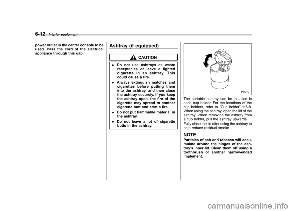
The portable ashtray can be installed in
each cup holder. For the locations of the
cup holders, refer to “Cup holder ”F 6-8.
When using the ashtray, open the lid of the
ashtray. When removing the ashtray from
a cup holder, pull the ashtray upwards.
Fully close the lid after using the ashtray to
help reduce residual smoke. NOTE
Particles of ash and tobacco will accu-
mulate around the hinges of the ash-tray ’s inner lid. Clean them off using a
toothbrush or another narrow-endedimplement.
Page 267 of 474
6-14Interior equipment
&Outback
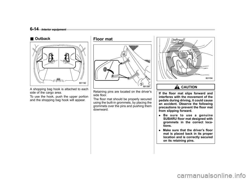
A shopping bag hook is attached to each
side of the cargo area.
To use the hook, push the upper portion
and the shopping bag hook will appear. Floor matRetaining pins are located on the driver
’s
side floor.
The floor mat should be properly secured
using the built-in grommets, by placing the
grommets over the pins and pushing themdownward.
CAUTION
If the floor mat slips forward and
interferes with the movement of the
pedals during driving, it could cause
an accident. Observe the following
precautions to prevent the floor mat
from slipping forward. . Be sure to use a genuine
SUBARU floor mat designed with
grommets in the correct loca-tions.
. Make sure that the driver ’s floor
mat is placed back in its proper
location and is correctly secured
on its retaining pins.
Page 270 of 474
&To install the cover housing
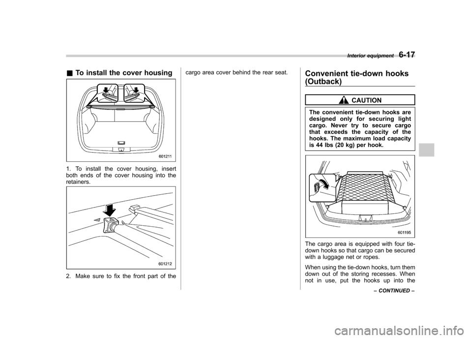
1. To install the cover housing, insert
both ends of the cover housing into theretainers.
2. Make sure to fix the front part of the cargo area cover behind the rear seat.
Convenient tie-down hooks
(Outback)
CAUTION
The convenient tie-down hooks are
designed only for securing light
cargo. Never try to secure cargo
that exceeds the capacity of the
hooks. The maximum load capacity
is 44 lbs (20 kg) per hook.
The cargo area is equipped with four tie-
down hooks so that cargo can be secured
with a luggage net or ropes.
When using the tie-down hooks, turn them
down out of the storing recesses. When
not in use, put the hooks up into the Interior equipment
6-17
– CONTINUED –
Page 282 of 474
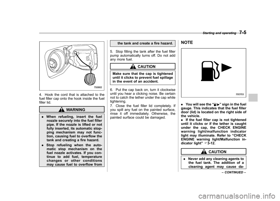
4. Hook the cord that is attached to the
fuel filler cap onto the hook inside the fuel
filler lid.
WARNING
. When refueling, insert the fuel
nozzle securely into the fuel filler
pipe. If the nozzle is lifted or not
fully inserted, its automatic stop-
ping mechanism may not func-
tion, causing fuel to overflow the
tank and creating a fire hazard.
. Stop refueling when the auto-
matic stop mechanism on the
fuel nozzle activates. If you con-
tinue to add fuel, temperature
changes or other conditions
may cause fuel to overflow from the tank and create a fire hazard.
5. Stop filling the tank after the fuel filler
pump automatically turns off. Do not add
any more fuel.
CAUTION
Make sure that the cap is tightened
until it clicks to prevent fuel spillage
in the event of an accident.
6. Put the cap back on, turn it clockwise
until you hear a clicking noise. Be certain
not to catch the tether under the cap whiletightening.
7. Close the fuel filler lid completely. If
you spill any fuel on the painted surface,
rinse it off immediately. Otherwise, the
painted surface could be damaged. NOTE
.
You will see the “”sign in the fuel
gauge. This indicates that the fuel filler
door (lid) is located on the right side of
the vehicle.. If the fuel filler cap is not tightened
until it clicks or if the tether is caught
under the cap, the CHECK ENGINE
warning light/malfunction indicator
light may illuminate. Refer to “CHECK
ENGINE warning light/Malfunction in-
dicator light ”F 3-12.
CAUTION
. Never add any cleaning agents to
the fuel tank. The addition of a
cleaning agent may cause da- Starting and operating
7-5
– CONTINUED –
Page 283 of 474
7-6Starting and operating
mage to the fuel system.
. After refueling, turn the cap to the
right until it clicks to ensure that
it is fully tightened. If the cap is
not securely tightened, fuel may
leak out while the vehicle is being
driven or fuel spillage could
occur in the event of an accident,
creating a fire hazard.
. Do not let fuel spill on the exterior
surfaces of the vehicle. Because
fuel may damage the paint, be
sure to wipe off any spilled fuel
quickly. Paint damage caused by
spilled fuel is not covered under
the SUBARU Limited Warranty.
. Always use a genuine SUBARU
fuel filler cap. If you use the
wrong cap, it may not fit, and
your fuel tank and emission con-
trol system may be damaged. It
could also lead to fuel spillage
and a fire.
. Immediately put fuel in the tank
whenever the low fuel warning
light illuminates. Engine misfires
as a result of an empty tank
could cause damage to the en-gine. State emission testing (U.S. only)
WARNING
Testing of an All-Wheel Drive model
must NEVER be performed on a
single two-wheel dynamometer. At-
tempting to do so will result in
uncontrolled vehicle movement and
may cause an accident or injuries to
persons nearby.
CAUTION
. At state inspection time, remem-
ber to tell your inspection or
service station in advance not to
place your SUBARU AWD vehicle
on a two-wheel dynamometer.
Otherwise, serious transmission
damage will result.
. Resultant vehicle damage due to
improper testing is not covered
under the SUBARU Limited War-
ranty and is the responsibility of
the state inspection program or
its contractors or licensees.
California and a number of federal states
have Inspection/Maintenance programs to inspect your vehicle
’s emission control
system. If your vehicle does not pass this
test, some states may deny renewal of
your vehicle ’s registration.
Your vehicle is equipped with a computer
that monitors the performance of the engine ’s emission control system. Certi-
fied emission inspectors will inspect the
On-Board Diagnostic (OBDII) system as
part of the state emission inspection
process. The OBDII system is designed
to detect engine and transmission pro-
blems that might cause the vehicle emis-
sions to exceed allowable limits. OBDII
inspections apply to all 1996 model year
and newer passenger cars and trucks.
Over 30 states plus the District of Colum-
bia have implemented emission inspec-
tion of the OBDII system. . The inspection of the OBDII system
consists of a visual operational check of the “CHECK ENGINE ”warning light/mal-
function indicator light (MIL) and an
examination of the OBDII system with an
electronic scan tool. . A vehicle
passes the OBDII system
inspection if proper operation of the “ CHECK ENGINE ”warning light is ob-
served, there are no stored diagnostic
trouble codes, and the OBDII readiness
monitors are all complete.
Page 288 of 474
preconditions before starting, and if all
safety parameters are correct, the engine
will start within 5 seconds. Upon success-
ful engine start, the remote start confirma-
tion transmitter button will flash twice
every 5 seconds* and the vehicle will
honk the horn and flash the side marker
lights, tail lights and the front position
lights once, then the lights will illuminate
and remain illuminated, indicating that the
engine is running. While the vehicle is
operating via the remote engine start
function, the power window features will
be disabled. Also, the system has a timer
and will shut down after 15 minutes if you
do not operate the vehicle. Press and hold the“
”button for 2 seconds to turn the
engine off. The remote start confirmation
transmitter button will flash three times*
indicating that the engine has shut down.
If the starter cranks but does not start or
starts and stalls, the remote engine start
system will power off and then attempt to
start the engine an additional three times
unless the remote engine start system
determines that a vehicle malfunction is
preventing the system from starting. If the
engine does not start after additional
attempts, the remote engine start system
will abort and return to a non-activatestate.
*: Provided that the remote engine start transmitter is within the operating range of
the system. &
Remote start safety features
For safety and security reasons, the
system will fail to start and honk the horn
twice or shut down the engine during
remote start operation if any of the
following occur: . Any of the doors or the trunk / rear gate
are open / opened (*the vehicle ’s horn will
honk six times and the side marker lights,
tail lights and the front position lights will
flash six times indicating that a vehicle
door or trunk / rear gate was open when
the remote engine start system wasactivated). . The brake pedal is depressed
. The key was already in the ignition
switch. The engine hood is opened
. The remote start system “Service
mode ”is engaged
. The vehicle ’s engine idle speed has
reached a level over 3,500 RPM. The alarm is triggered by opening a
door or the rear gate.. The select lever is not in the “P ”
position (AT and CVT models)
In addition to the items above, if the vehicle
’s engine management system
determines there is a safety risk due to a
vehicle related problem, the vehicle will
shut down and the vehicle ’s horn will honk
three times.
NOTE . If the alarm system is armed at the
time of remote engine start activation
(the security indicator light on the
combination meter is flashing), the
alarm system will remain armed
throughout the remote start run cycle.. If the alarm system is disarmed at
the time of remote engine start activa-
tion (the security indicator light on the
combination meter is not flashing), the
alarm system will remain disarmed
throughout the remote start run cycle. & Entering the vehicle while it
is running via remote start
1. Unlock the vehicle doors using the
remote keyless entry system. If the vehi-cle ’s doors are unlocked manually using
the key, the vehicle ’s alarm system will
trigger (if the alarm system is armed prior
to activating the remote engine start
system) and the engine will turn off.
Inserting the key into the ignition switch
and turning it to the “ON ”position or
pressing the unlock button “
”on the
Starting and operating
7-11
– CONTINUED –
Page 295 of 474

7-18Starting and operating
than 5 seconds in any position
except the “N ” or “P ” position
when the brake is applied or
when chocks are used in the
wheels. This may cause the
transmission fluid to overheat.
. Avoid shifting from one of the
forward driving positions into the“ R ” position or vice versa until
the vehicle has completely
stopped. Such shifting may
cause damage to the transmis-sion.
. When parking the vehicle, first
securely apply the parking brake
and then place the select lever inthe “P ” position. Avoid parking
for a long time with the select
lever in any other position as
doing so could result in a dead
battery.
NOTE . For AT models, when the engine
coolant temperature is still low, the
transmission will upshift to higher
engine speeds than when the coolant
temperature is sufficiently high in order
to shorten the warm-up time and
improve driveability. The gearshift tim-
ing will automatically shift to the nor- mal timing after the engine has warmedup..
Immediately after transmission fluid
is replaced, you may feel that the
transmission operation is somewhat
unusual. This results from invalidation
of data which the on-board computer
has collected and stored in memory to
allow the transmission to shift at the
most appropriate times for the current
condition of your vehicle. Optimized
shifting will be restored as the vehicle
continues to be driven for a while.. When driving a vehicle that is
equipped with CVT under continuous
heavy load conditions such as towing a
camper or climbing a long, steep hill,
the engine speed or the vehicle speed
may automatically be reduced. This is
not a malfunction. This phenomenon
results from the engine control func-
tion maintaining the cooling perfor-
mance of the vehicle. The engine and
vehicle speed will return to a normal
speed when the engine is able to
maintain the optimum cooling perfor-
mance after the heavy load decreases.
Driving under a heavy load must be
performed with extreme care. Do not
try to pass a vehicle in front when
driving on an uphill slope while towing.. The continuously variable transmis-
sion is a chain type system that provides superior transmission effi-
ciency for maximum fuel economy. At
times, depending on varying driving
conditions, a chain operating sound
may be heard that is characteristic of
this type of system.
& Select lever
: With the brake pedal depressed, shift
while pressing the button in
: Shift while pressing the button in: Shift without pressing the button
The select lever has four positions, “P ”,
“ R ”, “N ”, “D ”and also has a manual gate
for using the manual mode. ! P (Park)
This position is for parking the vehicle and
starting the engine.