2012 SUBARU OUTBACK tow bar
[x] Cancel search: tow barPage 304 of 474
that full vehicle control will be
maintained at all times and under
all conditions, its activation
should be seen as a sign that
the speed of the vehicle should
be reduced considerably.
. Whenever suspension compo-
nents, steering components, or
an axle are removed from a
vehicle equipped with the Vehicle
Dynamics Control system, have
an inspection of that system
performedbyanauthorized
SUBARU dealer.
. The following precautions should
be observed in order to ensure
that the Vehicle Dynamics Con-
trol system is operating properly. – All four wheels should be
fitted with tires of the same
size, type, and brand. Further-
more, the amount of wear
should be the same for all
four tires.
– Keep the tire pressure at the
proper level as shown on the
vehicle placard attached to
the driver ’s side door pillar.
– Use only the specified tem-
porary spare tire to replace a
flat tire. With a temporary spare tire, the effectiveness of
the Vehicle Dynamics Control
system is reduced and this
should be taken into account
when driving the vehicle in
such a condition.
. If non-matching tires are used,
the Vehicle Dynamics Control
system may not operate cor-
rectly.
In the event of wheelspin and/or skidding
on a slippery road surface and/or during
cornering and/or an evasive maneuver,
the Vehicle Dynamics Control system
adjusts the engine ’s output and the
wheels ’respective braking forces to help
maintain traction and directional control. . Traction Control Function
The traction control function is designed to
prevent spinning of the driving wheels on
slippery road surfaces, thereby helping to
maintain traction and directional control.
Activation of this function is indicated by
flashing of the Vehicle Dynamics Control
operation indicator light. . Skid Suppression Function
The skid suppression function is designed
to help maintain directional stability by
suppressing the wheels ’tendency to slide
sideways during steering operations. Acti- vation of this function is indicated by
flashing of the Vehicle Dynamics Control
operation indicator light.
NOTE . The Vehicle Dynamics Control sys-
tem may be considered normal when
the following conditions occur.
–Slight twitching of the brake
pedal is felt. – The vehicle or steering wheel
shakes to a small degree.– An operating sound from the
engine compartment is heard
briefly when starting the engine
and when driving off after starting
the engine. – The brake pedal seems to jolt
when driving off after starting the engine.
. In the following circumstances, the
vehicle may be less stable than it feels
to the driver. The Vehicle Dynamics
Control System may therefore operate.
Such operation does not indicate a
system malfunction.
–on gravel-covered or rutted
roads – on unfinished roads
– when the vehicle is towing a
trailer– when the vehicle is fitted with Starting and operating
7-27
– CONTINUED –
Page 308 of 474
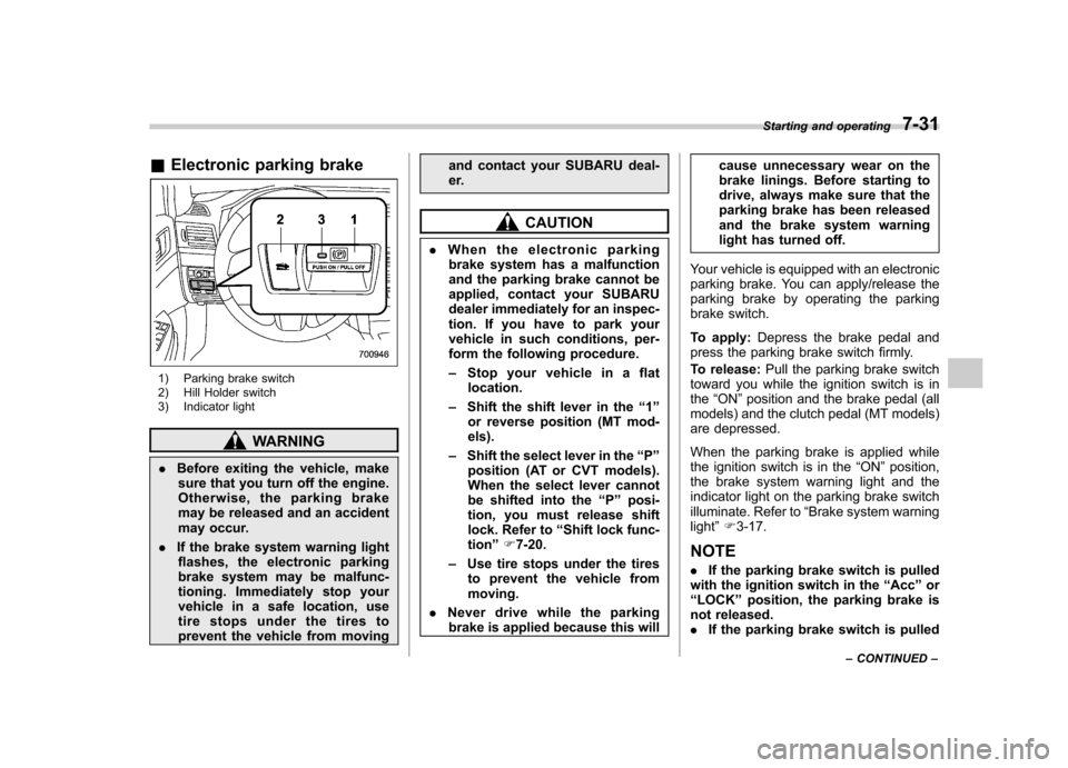
&Electronic parking brake
1) Parking brake switch
2) Hill Holder switch
3) Indicator light
WARNING
. Before exiting the vehicle, make
sure that you turn off the engine.
Otherwise, the parking brake
may be released and an accident
may occur.
. If the brake system warning light
flashes, the electronic parking
brake system may be malfunc-
tioning. Immediately stop your
vehicle in a safe location, use
tire stops under the tires to
prevent the vehicle from moving and contact your SUBARU deal-
er.
CAUTION
. When the electronic parking
brake system has a malfunction
and the parking brake cannot be
applied, contact your SUBARU
dealer immediately for an inspec-
tion. If you have to park your
vehicle in such conditions, per-
form the following procedure. – Stop your vehicle in a flat
location.
– Shift the shift lever in the “1 ”
or reverse position (MT mod- els).
– Shift the select lever in the “P ”
position (AT or CVT models).
When the select lever cannot
be shifted into the “P ” posi-
tion, you must release shift
lock. Refer to “Shift lock func-
tion ”F 7-20.
– Use tire stops under the tires
to prevent the vehicle frommoving.
. Never drive while the parking
brake is applied because this will cause unnecessary wear on the
brake linings. Before starting to
drive, always make sure that the
parking brake has been released
and the brake system warning
light has turned off.
Your vehicle is equipped with an electronic
parking brake. You can apply/release the
parking brake by operating the parking
brake switch.
To apply: Depress the brake pedal and
press the parking brake switch firmly.
To release: Pull the parking brake switch
toward you while the ignition switch is in the “ON ”position and the brake pedal (all
models) and the clutch pedal (MT models)
are depressed.
When the parking brake is applied while
the ignition switch is in the “ON ”position,
the brake system warning light and the
indicator light on the parking brake switch
illuminate. Refer to “Brake system warning
light ”F 3-17.
NOTE . If the parking brake switch is pulled
with the ignition switch in the “Acc ”or
“ LOCK ”position, the parking brake is
not released. . If the parking brake switch is pulled Starting and operating
7-31
– CONTINUED –
Page 316 of 474
New vehicle break-in driving–the first
1,000 miles (1,600 km) ..................................... 8-2
Fuel economy hints ............................................ 8-2
Engine exhaust gas (carbon monoxide) ............ 8-2
Catalytic converter .............................................. 8-3
Periodic inspections ........................................... 8-4
Driving in foreign countries ............................... 8-4
Driving tips for AWD vehicles ............................ 8-5
Off road driving ................................................... 8-6
Legacy ................................................................ 8-6
Outback .............................................................. 8-6
Winter driving ...................................................... 8-8
Operation during cold weather ............................. 8-8
Driving on snowy and icy roads ......................... 8-10
Corrosion protection .......................................... 8-11
Snow tires ......................................................... 8-11
Tire chains ......................................................... 8-12 Rocking the vehicle
........................................... 8-12
Loading your vehicle ......................................... 8-12
Vehicle capacity weight ...................................... 8-13
GVWR and GAWR (Gross Vehicle Weight Rating and Gross Axle Weight Rating) ........................ 8-14
Roof rails with integrated crossbars (Outback) ........................................................ 8-14
Trailer hitch (Outback —if equipped) .............. 8-17
Connecting a trailer ........................................... 8-18
When you do not tow a trailer .. .......................... 8-19
Trailer towing ..................................................... 8-19
Warranties and maintenance .............................. 8-19
Maximum load limits .......................................... 8-20
Trailer hitches .................................................... 8-23
Connecting a trailer ........................................... 8-24
Trailer towing tips .............................................. 8-25Driving tips
8
Page 321 of 474
8-6Driving tips
conditions than a two wheel drive vehicle.
There is little difference in handling,
however, during extremely sharp turns or
sudden braking. Therefore, when driving
down a slope or turning corners, be sure
to reduce your speed and maintain an
ample distance from other vehicles. .Always check the cold tire pressure
before starting to drive. The recom-
mended tire pressure is provided on the
tire placard, which is located on the door
pillar on the driver ’s side.
. There are some precautions that you
must observe when towing your vehicle.
For detailed information, refer to “Towing ”
F 9-13. Off road driving
WARNING
. Always maintain a safe driving
speed according to the road and
weather conditions in order to
avoid having an accident on a
sharp turn, during sudden brak-
ing or under other similar condi-tions.
. Always use the utmost care in
driving –overconfidence be-
cause you are driving an All-
Wheel Drive vehicle could easily
lead to a serious accident.
& Legacy
Your AWD vehicle is neither a conven-
tional off-road vehicle nor an all terrain
vehicle. It is a passenger car designed
primarily for on-road use. The AWD
feature gives it some limited off-road
capabilities in situations in which the
driving surface is relatively level, obstruc-
tion-free and otherwise similar to on-road
driving conditions. Operating it under other
than those conditions could subject the
vehicle to excessive stress which might
result in damage not eligible for repair under warranty. If you do take your
SUBARU off road, you should review the
common sense precautions in the next
section (applicable to the Outback) for
general guidance. But please keep in
mind that your vehicle
’s off-road capabil-
ities are more limited than those of theOutback.
Never attempt to drive through pools and
puddles, or roads flooded with water.
Water entering the engine air intake or
the exhaust pipe or water splashing onto
electrical parts may damage your vehicle
and may cause it to stall. & Outback
Because of the AWD feature and higher
ground clearance, your SUBARU can be
driven on ordinary roads or off-road. But
please keep in mind that an AWD
SUBARU is a passenger car and is
neither a conventional off-road vehicle
nor an all-terrain vehicle. If you do take
your SUBARU off-road, certain common
sense precautions such as those in the
following list should be taken: . Make certain that you and all of your
passengers are wearing seatbelts. . Carry some emergency equipment,
such as a towing rope or chain, a shovel,
wheel blocks, first aid kit and cell phone or
citizens band radio.
Page 331 of 474
8-16Driving tips
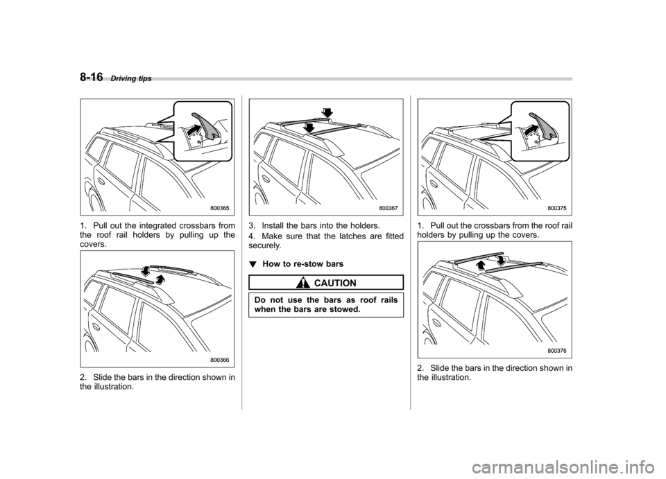
1. Pull out the integrated crossbars from
the roof rail holders by pulling up thecovers.
2. Slide the bars in the direction shown in
the illustration.
3. Install the bars into the holders.
4. Make sure that the latches are fitted
securely. !How to re-stow bars
CAUTION
Do not use the bars as roof rails
when the bars are stowed.
1. Pull out the crossbars from the roof rail
holders by pulling up the covers.
2. Slide the bars in the direction shown in
the illustration.
Page 332 of 474
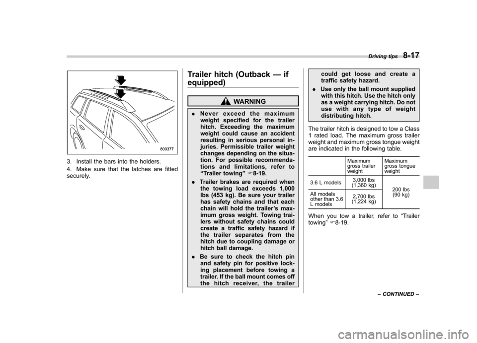
3. Install the bars into the holders.
4. Make sure that the latches are fitted
securely.Trailer hitch (Outback
—if
equipped)
WARNING
. Never exceed the maximum
weight specified for the trailer
hitch. Exceeding the maximum
weight could cause an accident
resulting in serious personal in-
juries. Permissible trailer weight
changes depending on the situa-
tion. For possible recommenda-
tions and limitations, refer to“ Trailer towing ”F 8-19.
. Trailer brakes are required when
the towing load exceeds 1,000
lbs (453 kg). Be sure your trailer
has safety chains and that each
chain will hold the trailer ’s max-
imum gross weight. Towing trai-
lers without safety chains could
create a traffic safety hazard if
the trailer separates from the
hitch due to coupling damage or
hitch ball damage.
. Be sure to check the hitch pin
and safety pin for positive lock-
ing placement before towing a
trailer. If the ball mount comes off
the hitch receiver, the trailer could get loose and create a
traffic safety hazard.
. Use only the ball mount supplied
with this hitch. Use the hitch only
as a weight carrying hitch. Do not
use with any type of weight
distributing hitch.
The trailer hitch is designed to tow a Class
1 rated load. The maximum gross trailer
weight and maximum gross tongue weight
are indicated in the following table. Maximum
gross trailerweightMaximum
gross tongueweight
3.6 L models 3,000 lbs
(1,360 kg) 200 lbs
(90 kg)
All models
other than 3.6
L models 2,700 lbs
(1,224 kg)
When you tow a trailer, refer to “Trailer
towing ”F 8-19. Driving tips
8-17
– CONTINUED –
Page 334 of 474
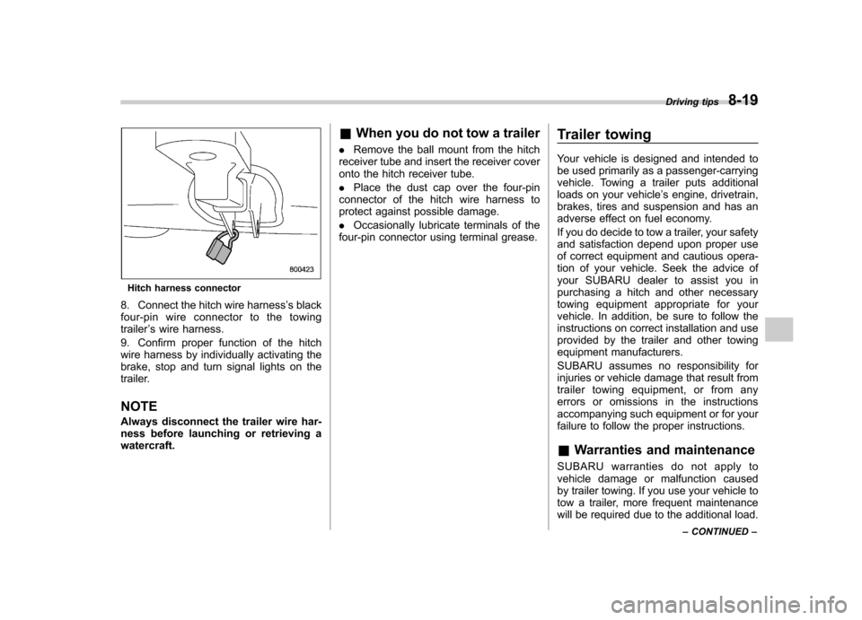
Hitch harness connector
8. Connect the hitch wire harness ’s black
four-pin wire connector to the towing trailer ’s wire harness.
9. Confirm proper function of the hitch
wire harness by individually activating the
brake, stop and turn signal lights on the
trailer. NOTE
Always disconnect the trailer wire har-
ness before launching or retrieving awatercraft. &
When you do not tow a trailer
. Remove the ball mount from the hitch
receiver tube and insert the receiver cover
onto the hitch receiver tube. . Place the dust cap over the four-pin
connector of the hitch wire harness to
protect against possible damage. . Occasionally lubricate terminals of the
four-pin connector using terminal grease. Trailer towing
Your vehicle is designed and intended to
be used primarily as a passenger-carrying
vehicle. Towing a trailer puts additional
loads on your vehicle
’s engine, drivetrain,
brakes, tires and suspension and has an
adverse effect on fuel economy.
If you do decide to tow a trailer, your safety
and satisfaction depend upon proper use
of correct equipment and cautious opera-
tion of your vehicle. Seek the advice of
your SUBARU dealer to assist you in
purchasing a hitch and other necessary
towing equipment appropriate for your
vehicle. In addition, be sure to follow the
instructions on correct installation and use
provided by the trailer and other towing
equipment manufacturers.
SUBARU assumes no responsibility for
injuries or vehicle damage that result from
trailer towing equipment, or from any
errors or omissions in the instructions
accompanying such equipment or for your
failure to follow the proper instructions.
& Warranties and maintenance
SUBARU warranties do not apply to
vehicle damage or malfunction caused
by trailer towing. If you use your vehicle to
tow a trailer, more frequent maintenance
will be required due to the additional load. Driving tips
8-19
– CONTINUED –
Page 339 of 474
8-24Driving tips
trailer. !Outback
The use of a genuine SUBARU trailer
hitch is recommended. A genuine
SUBARU hitch is available from your
SUBARU dealer.
If use of a non-genuine hitch is unavoid-
able, be sure the hitch is suited to your
vehicle and trailer. Consult with a profes-
sional hitch supplier to assist you in
choosing an appropriate hitch for your
vehicle. Be sure to follow all of the hitchmanufacturer ’s instructions for installation
and use.
Never use a hitch that mounts only to the
rear bumper. The bumper is not designed
to handle that type of load.
For all types of hitches, regularly check
that the hitch mounting bolts and nuts aretight. ! Legacy
SUBARU does not offer accessory trailer
hitches. Consult with a professional hitch
supplier to assist you in choosing an
appropriate hitch for your vehicle. Be sure
to follow all of the hitch manufacturer ’s
instructions for installation and use.
Never use a hitch that mounts only to the
rear bumper. The bumper is not designed
to handle that type of load. Regularly check that the hitch mounting
bolts and nuts are tight.
& Connecting a trailer
! Trailer brakes
WARNING
. Adequate size trailer brakes are
required when the trailer and its
cargo exceed 1,000 lbs (453 kg)
total weight.
. Do not directly connect your
trailer ’s hydraulic brake system
to the hydraulic brake system in
your vehicle. Direct connection
would cause the vehicle ’s brake
performance to deteriorate and
could lead to an accident.
If your trailer ’s total weight (trailer weight
plus its cargo weight) exceeds 1,000 lbs
(453 kg), the trailer is required to be
equipped with its own brake system.
Electric brakes or surge brakes are
recommended, and must be installed
properly. Check that your trailer ’s brakes
conform with Federal, state/province and/
or other applicable regulations. YourSUBARU ’s brake system is not designed
to be tapped into the trailer ’s hydraulic
brake system. Please ask your SUBARU dealer and professional trailer supplier for
more information about the trailer
’s brake
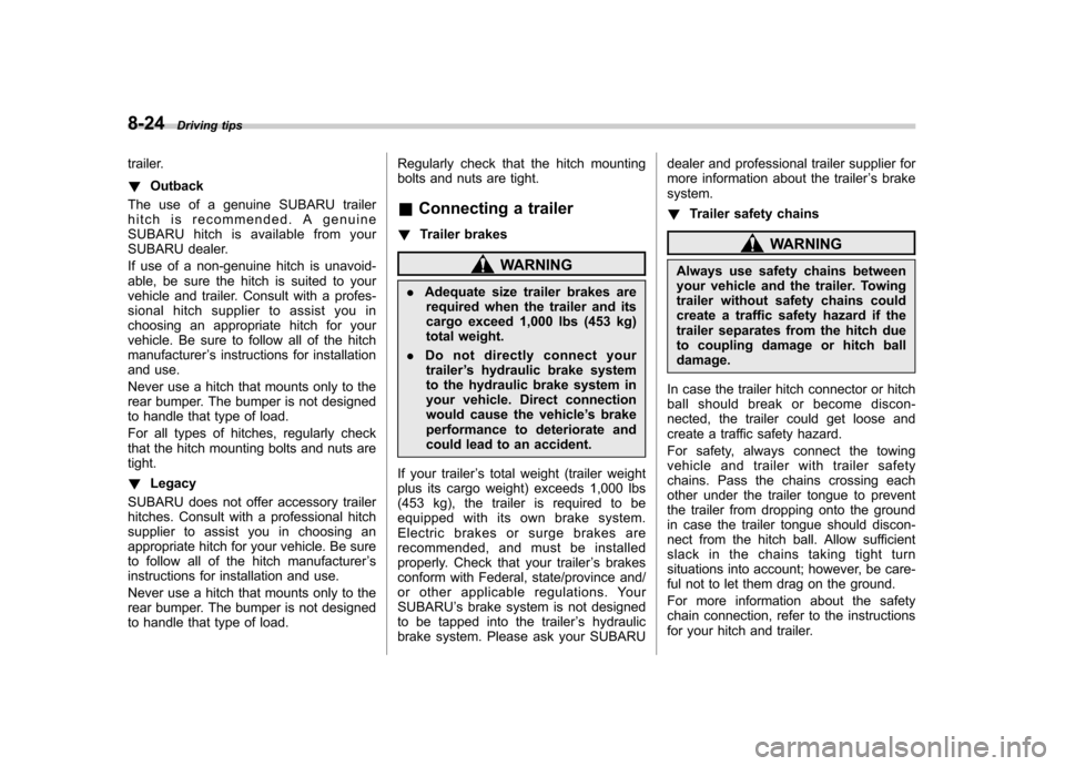
system. ! Trailer safety chains
WARNING
Always use safety chains between
your vehicle and the trailer. Towing
trailer without safety chains could
create a traffic safety hazard if the
trailer separates from the hitch due
to coupling damage or hitch balldamage.
In case the trailer hitch connector or hitch
ball should break or become discon-
nected, the trailer could get loose and
create a traffic safety hazard.
For safety, always connect the towing
vehicle and trailer with trailer safety
chains. Pass the chains crossing each
other under the trailer tongue to prevent
the trailer from dropping onto the ground
in case the trailer tongue should discon-
nect from the hitch ball. Allow sufficient
slack in the chains taking tight turn
situations into account; however, be care-
ful not to let them drag on the ground.
For more information about the safety
chain connection, refer to the instructions
for your hitch and trailer.