2012 SUBARU OUTBACK instrument panel
[x] Cancel search: instrument panelPage 177 of 474

4-6Climate control
and become damaged, the system may
not be able to control the interior tempera-
ture correctly. To avoid damaging the
sensors, observe the following precau-tions: –Do not subject the sensors to impact.
– Keep water away from the sensors.
– Do not cover the sensors.
The sensors are located as follows:– Solar sensor: beside the speaker grille
on the dashboard– Interior air temperature sensor: on the
side of the driver-side part of the center panel – Outside temperature sensor: behind
front grille. Manual climate control &
Airflow mode selection
Select the preferred airflow mode by
performing the following procedure. . Press the preferred airflow control
button (type A) . Press the airflow mode selection button
or defroster button (type B)
Airflow modes are as follows.
(Ventilation): Instrument panel outlets
(Bi-level): Instrument panel outlets and the
foot outlets
(Heat): Foot outlets, both side outlets of
the instrument panel and some through
windshield defroster outlets (A small
amount of air flows to the windshield and
Page 178 of 474

both side windows to prevent fogging.)
(Heat-def): Windshield defroster outlets,
foot outlets and both side outlets of the
instrument panel
(Defrost): Windshield defroster outlets and
both side outlets of the instrument panel&
Temperature control
! Type A
Turn the temperature control dial over a
range from the blue side (cool) to red side
(warm) to regulate the temperature of
airflow from the air outlets. ! Type B
To increase the temperature setting, press the “
”side of the temperature control
button. To decrease the temperature
setting, press the “
”side of the tempera-
ture control button.
Each temperature setting is shown on the
display. When “LO ”is shown, the system
provides maximum cooling performance.When “HI ”is shown, the system provides
maximum heating performance.
NOTE
When the “DUAL ”button is pressed,
separate temperature settings for the driver ’s side and passenger ’s side can
be enabled (DUAL mode). To cancel the
DUAL mode, press the “DUAL ”button
again. The temperature setting for thepassenger ’s side becomes the same as
the setting for the driver ’s side.
& Fan speed control
The fan operates only when the ignition switch is in the
“ON ”position. Select the
preferred fan speed by turning the fan
speed control dial (type A), or by pressing
the fan speed control buttons (type B).
& Air conditioner control
The air conditioner operates only when
the engine is running.
Press the air conditioner button while the
fan is in operation to turn on the air
conditioner. When the air conditioner is
on, the indicator light on the air conditioner
button (type A)/ “A/C ”indicator light (type
B) illuminates.
To turn off the air conditioner, press the
button again. The indicator light will turnoff. NOTE
For efficient defogging or dehumidify-
ing in cold weather, turn on the air
conditioner. & Air inlet selection
Select the air inlet by pressing the air inlet
selection button.
ON position (recirculation) : Interior air is
recirculated inside the vehicle. Press the
air inlet selection button to the ON position
for fast cooling with the air conditioner or
when driving on a dusty road. When the Climate control
4-7
– CONTINUED –
Page 182 of 474

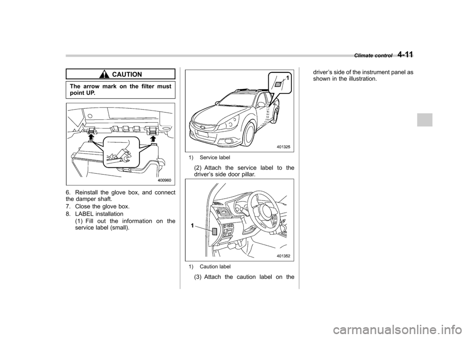
CAUTION
The arrow mark on the filter must
point UP.
6. Reinstall the glove box, and connect
the damper shaft.
7. Close the glove box.
8. LABEL installation (1) Fill out the information on the
service label (small).
1) Service label
(2) Attach the service label to the driver ’s side door pillar.
1) Caution label
(3) Attach the caution label on the driver
’s side of the instrument panel as
shown in the illustration. Climate control
4-11
Page 366 of 474

Exterior care....................................................... 10-2
Washing ............................................................. 10-2
Waxing and polishing ......................................... 10-3
Cleaning aluminum wheels ................................. 10-3
Corrosion protection .......................................... 10-4
Most common causes of corrosion ..................... 10-4
To help prevent corrosion ................................... 10-4 Cleaning the interior
.......................................... 10-5
Seat fabric ......................................................... 10-5
Leather seat materials ........................................ 10-5
Synthetic leather upholstery ............................... 10-5
Climate control panel, audio panel, instrument panel, console panel, switches, combination
meter, and other plastic surface ....................... 10-5
Monitor (if equipped) .......................................... 10-6Appearance care
10
Page 370 of 474

Cleaning the interior
Use a soft, damp cloth to clean the climate
control panel, audio equipment, instru-
ment panel, center console, combination
meter panel, and switches. (Do not use
organic solvents.) &Seat fabric
Remove loose dirt, dust or debris with a
vacuum cleaner. If the dirt is caked on the
fabric or hard to remove with a vacuum
cleaner, use a soft brush then vacuum it.
Wipe the fabric surface with a tightly
wrung cloth and dry the seat fabric
thoroughly. If the fabric is still dirty, wipe
using a solution of mild soap and luke-
warm water then dry thoroughly.
If the stain does not come out, try a
commercially available fabric cleaner. Use
the cleaner on a hidden place and make
sure it does not affect the fabric adversely.
Use the cleaner according to its instruc-tions. NOTE
When cleaning the seat, do not use
benzine, paint thinner, or any similarmaterials. &
Leather seat materials
The leather used by SUBARU is a high
quality natural product which will retain its
distinctive appearance and feel for many
years with proper care.
Allowing dust or road dirt to build up on the
surface can cause the material to become
brittle and to wear prematurely. Regular
cleaning with a soft, moist, natural fiber
cloth should be performed monthly, taking
care not to soak the leather or allow water
to penetrate the stitched seams.
A mild detergent suitable for cleaning
woolen fabrics may be used to remove
difficult dirt spots, rubbing with a soft, dry
cloth afterwards to restore the luster. If
your SUBARU is to be parked for a long
time in bright sunlight, it is recommended
that the seats and headrests be covered,
or the windows shaded, to prevent fading
or shrinkage.
Minor surface blemishes or bald patches
may be treated with a commercial leather
spray lacquer. You will discover that each
leather seat section will develop soft folds
or wrinkles, which is characteristic of
genuine leather. & Synthetic leather upholstery
The synthetic leather material used on the
SUBARU may be cleaned using mild soap or detergent and water, after first vacuum-
ing or brushing away loose dirt. Allow the
soap to soak in for a few minutes and wipe
off with a clean, damp cloth. Commercial
foam-type cleaners suitable for synthetic
leather materials may be used when
necessary. NOTE
Strong cleaning agents such as sol-
vents, paint thinners, window cleaner
or gasoline must never be used on
leather or synthetic interior materials. &
Climate control panel, audio
panel, instrument panel,
console panel, switches,
combination meter, and other
plastic surface
Use a soft, damp cloth to clean the climate
control panel, audio equipment, instru-
ment panel, center console, combination
meter panel, and switches. NOTE
Do not use organic solvents such as
paint thinners or gasoline, or strong
cleaning agents that contain thosesolvents. Appearance care
10-5
– CONTINUED –
Page 378 of 474

&Removing air intake duct
Use a screwdriver to undo the clips on the
air intake duct, then remove the air intake
duct. Refer to “Type A clips ”F 11-5.
& Pulling off the fender lining
It is necessary to pull off the fender lining
when replacing some bulbs.
1. Start the engine and turn the steering
wheel fully in the opposite direction of the
bulb to be replaced.
2. Stop the engine.
3. Remove the clip from the fender lining.
Refer to “Type B clips ”F 11-5.
4. Pull off the fender lining. Engine hood
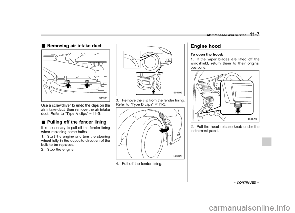
To open the hood:
1. If the wiper blades are lifted off the
windshield, return them to their originalpositions.
2. Pull the hood release knob under the
instrument panel.
Maintenance and service
11-7
– CONTINUED –
Page 402 of 474

tire placard. Specifically, inflate them by an
extra 1 psi (6.9 kPa, 0.07 kgf/cm2) for
every difference of 10 8F (5.6 8C) between
the temperature in the garage and the
temperature outside. By way of example,
the following table shows the required tire
pressures that correspond to various out-
side temperatures when the temperature
in the garage is 60 8F (15.6 8C).
Example:
Tire size: P215/70R16 99S, P225/60R17 98T
Standard tire pressures:
Front: 32 psi (220 kPa, 2.2 kgf/cm
2)
Rear: 30 psi (210 kPa, 2.1 kgf/cm2)
Garage temperature: 60 8F (15.6 8C)
Outside
temperature Adjusted pressure
[psi (kPa, kgf/cm
2)]
Front Rear
30 8F( �18C) 35 (240, 2.4) 33 (230, 2.3)
10 8F( �12 8C) 37
(255, 2.55) 35
(240, 2.4)
� 10 8F
( � 23 8C) 39 (270, 2.7)
37 (255, 2.55)
Example:
Tire size: P205/60R16 91V, P215/50R17
90V, P225/50R17 93V, 225/45R18 91W
Standard tire pressures:
Front: 33 psi (230 kPa, 2.3 kgf/cm
2) Rear: 32 psi (220 kPa, 2.2 kgf/cm
2)
Garage temperature: 60 8F (15.6 8C)
Outside
temperature Adjusted pressure
[psi (kPa, kgf/cm
2)]
Front Rear
30 8F( �18C) 36 (250, 2.5) 35 (240, 2.4)
10 8F( �12 8C) 38
(265, 2.65) 37
(255, 2.55)
� 10 8F
( � 23 8C) 40 (280, 2.8)
39 (270, 2.7)
If the low tire pressure warning light
illuminates when you drive the vehicle in
cold outside air after adjusting the tire
pressures in a warm garage, re-adjust the
tire pressures using the method described
above. Then, increase the vehicle speed
to at least 20 mph (32 km/h) and check to
see that the low tire pressure warning light
goes off a few minutes later. If the low tire
pressure warning light does not go off, the
tire pressure monitoring system may not
be functioning normally. In this event, go
to a SUBARU dealer to have the system
inspected as soon as possible.
While the vehicle is driven, friction be-
tween tires and the road surface causes
the tires to warm up. After illumination of
the low tire pressure warning light, any
increase in the tire pressures caused by
an increase in the outside air temperature or by an increase in the temperature in the
tires can cause the low tire pressure
warning light to go off.
System resetting is necessary when the
wheels are changed (for example, a
switch to snow tires) and new TPMS
valves are installed on the newly fitted
wheels. Have this work performed by a
SUBARU dealer following wheel replace-ment.
It may not be possible to install TPMS
valves on certain wheels that are on the
market. Therefore, if you change the
wheels (for example, a switch to snow
tires), use wheels that have the same part
number as the standard-equipment
wheels. Without four operational TPMS
valve/sensors on the wheels, the TPMS
will not fully function and the warning light
in the instrument panel will illuminate
steadily after blinking for approximately
one minute.
When a tire is replaced, adjustments are
necessary to ensure continued normal
operation of the tire pressure monitoring
system. As with wheel replacement, there-
fore, you should have the work performed
by a SUBARU dealer.
Maintenance and service
11-31
– CONTINUED –
Page 415 of 474

11-44Maintenance and service
Fuses
CAUTION
Never replace a fuse with one hav-
ing a higher rating or with material
other than a fuse because serious
damage or a fire could result.
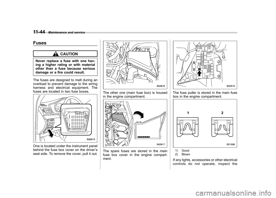
The fuses are designed to melt during an
overload to prevent damage to the wiring
harness and electrical equipment. The
fuses are located in two fuse boxes.
One is located under the instrument panel
behind the fuse box cover on the driver ’s
seat side. To remove the cover, pull it out.
The other one (main fuse box) is housed
in the engine compartment.
The spare fuses are stored in the main
fuse box cover in the engine compart-ment.
The fuse puller is stored in the main fuse
box in the engine compartment.
1) Good
2) Blown
If any lights, accessories or other electrical
controls do not operate, inspect the