2012 SUBARU IMPREZA WRX cooling
[x] Cancel search: coolingPage 166 of 416

Ventilator.............................................................. 4-2
Airflow selection ................................................. 4-2
Center and side ventilators .................................. 4-3
Manual climate control system (if equipped) .......................................................... 4-3
Control panel ...................................................... 4-3
Heater operation ................................................. 4-5
Air conditioner operation ..................................... 4-7
Automatic climate control system (if equipped) .......................................................... 4-8
Control panel ...................................................... 4-8
To use as full-automatic climate control system .............................................................. 4-8
To use as semi-automatic climate control system .............................................................. 4-8
Fan speed control dial ......................................... 4-9
Temperature control dial ...................................... 4-9
Airflow control dial .............................................. 4-9
Air inlet selection button .................................... 4-10 Air conditioner button
........................................ 4-11
Temperature sensors ......................................... 4-11
Operating tips for heater and air conditioner ...................................................... 4-12
Cleaning ventilation grille ................................... 4-12
Efficient cooling after parking in direct sunlight ........................................................... 4-12
Lubrication oil circulation in the refrigerant circuit .............................................................. 4-12
Checking air conditioning system before summer season ............................................................ 4-12
Cooling and dehumidifying in high humidity and low temperature weather conditions ................. 4-12
Air conditioner compressor shut-off when engine is heavily loaded .............................................. 4-13
Refrigerant for your climate control system ... ..... 4-13
Air filtration system ........................................... 4-13
Replacing an air filter ......................................... 4-13Climate control
4
Page 169 of 416

4-4Climate control
! Fan speed control dial
The fan operates only when the ignition
switch is turned to the “ON ”position. The
fan speed control dial is used to select
four fan speeds. ! Airflow control dial
Each dial position activates the following
air outlets.
(Ventilation): Instrument panel outlets
(Bi-level): Instrument panel outlets and
foot outlets
(Heat): Foot outlets, both side outlets of
the instrument panel and some through
windshield defroster outlets (A small
amount of air flows to the windshield and
both side windows to prevent fogging.)
(Heat-def): Windshield defroster out-
lets, foot outlets and both side outlets of
the instrument panel
: Windshield defroster outlets and both
side outlets of the instrument panel
For details, refer to “Airflow selection ”F 4-
2. NOTE
When the dial is placed in the “
”or
“” position, the air conditioner com-
pressor operates automatically regard- less of the position of the air condi-
tioner button to defog the windshield
more quickly. However the indicator on
the air conditioner button will not
illuminate. At the same time, the air
inlet selection is automatically set to“
outside air ”mode.
In this state, you cannot select “recir-
culation ”mode by manually pressing
the air inlet selection button.
Also, you cannot stop the air condi-
tioner compressor by pressing the air
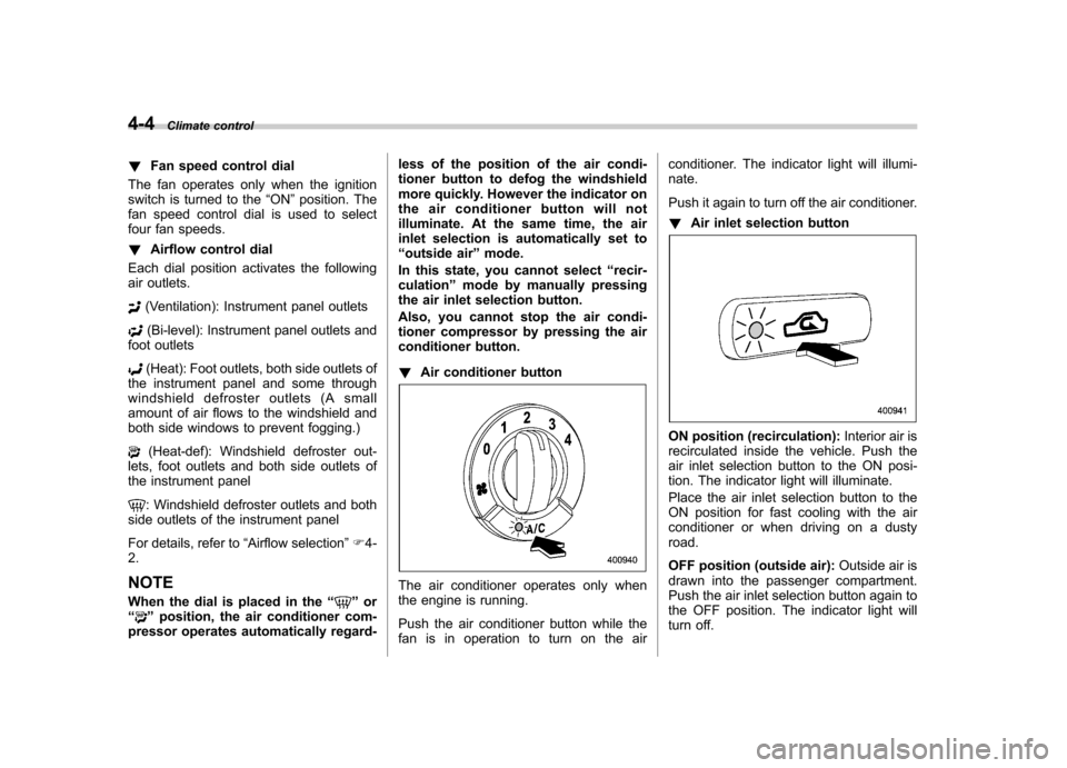
conditioner button. ! Air conditioner button
The air conditioner operates only when
the engine is running.
Push the air conditioner button while the
fan is in operation to turn on the air conditioner. The indicator light will illumi-nate.
Push it again to turn off the air conditioner. !
Air inlet selection button
ON position (recirculation): Interior air is
recirculated inside the vehicle. Push the
air inlet selection button to the ON posi-
tion. The indicator light will illuminate.
Place the air inlet selection button to the
ON position for fast cooling with the air
conditioner or when driving on a dustyroad.
OFF position (outside air): Outside air is
drawn into the passenger compartment.
Push the air inlet selection button again to
the OFF position. The indicator light will
turn off.
Page 172 of 416

inletselectionbuttonintheON
position may fog up the windows.
Switch to the OFF position as soon
as the outside dusty conditionclears.
& Air conditioner operation
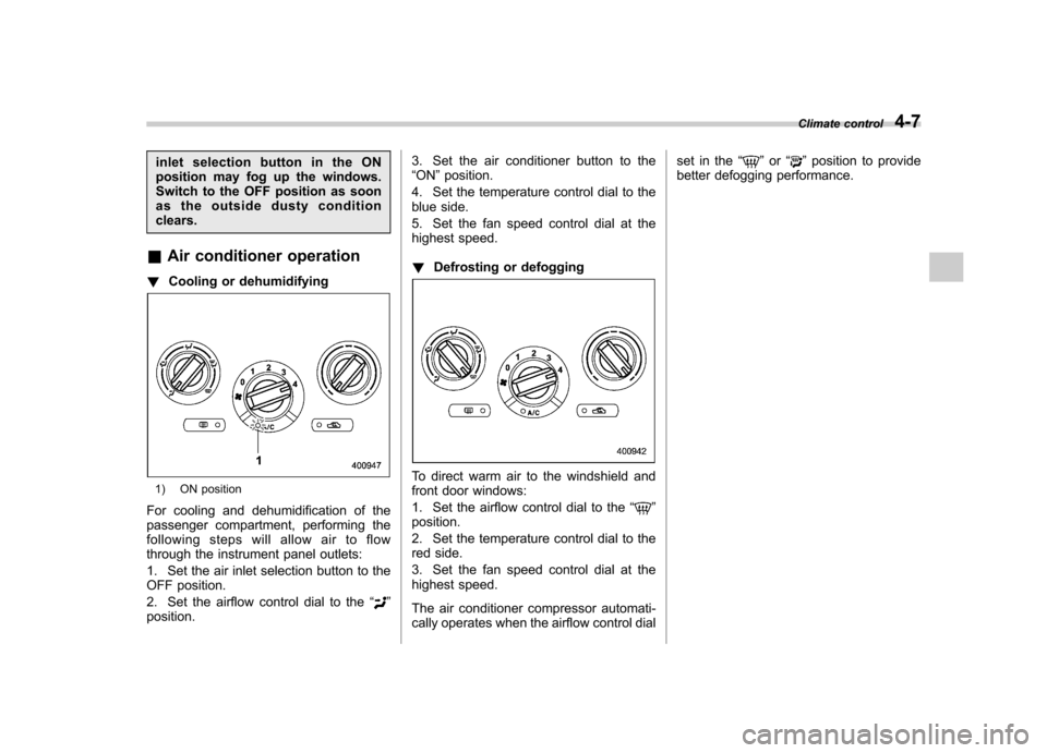
! Cooling or dehumidifying
1) ON position
For cooling and dehumidification of the
passenger compartment, performing the
following steps will allow air to flow
through the instrument panel outlets:
1. Set the air inlet selection button to the
OFF position.
2. Set the airflow control dial to the “
”
position. 3. Set the air conditioner button to the “
ON ”position.
4. Set the temperature control dial to the
blue side.
5. Set the fan speed control dial at the
highest speed. ! Defrosting or defogging
To direct warm air to the windshield and
front door windows:
1. Set the airflow control dial to the “
”
position.
2. Set the temperature control dial to the
red side.
3. Set the fan speed control dial at the
highest speed.
The air conditioner compressor automati-
cally operates when the airflow control dial set in the
“
”or “”position to provide
better defogging performance. Climate control
4-7
Page 174 of 416

&Fan speed control dial
The fan operates only with the ignition
switch in the ON position. The fan speed
control dial is used to select the AUTO
(automatic control) mode or to select the
desired fan speed. The dial ’s positions
and their functions are as follows. OFF: The fan does not operate.
AUTO: The fan speed is adjusted auto-
maticallyinaccordancewiththeair
temperature inside and outside the pas-
senger compartment, the intensity of sun-
light, and other factors. SUBARU recom-
mends using the AUTO position.
Other positions: The fan speed can be
adjusted in 7 steps. NOTE
With the fan speed control dial in the
AUTO position and the airflow control
dial in the
“
”, “”,or “”position,
the fan does not operate during engine
warm-up until the engine coolant tem-
perature exceeds approximately 122 8F
(50 8C).
& Temperature control dial
This dial is used to set the desired interior
temperature. With the dial set to your
desired temperature, the system automa-
tically adjusts the temperature of air
supplied from the outlets such that the
desired temperature is achieved andmaintained.
If the dial is turned fully counterclockwise, the system gives maximum cooling per-
formance. If the dial is turned fully clock-
wise, the system gives maximum heatingperformance. &
Airflow control dial
Each dial position activates the following
air outlets. AUTO: The airflow control is adjusted
automatically in accordance with the air
temperature inside and outside the pas-
senger compartment, the intensity of sun-
light, and other factors. SUBARU recom-
mends using the AUTO position.
(Ventilation): Instrument panel outlets
(Bi-level): Instrument panel outlets and
foot outlets
(Heat): Foot outlets, both side outlets of Climate control
4-9
– CONTINUED –
Page 175 of 416

4-10Climate control
the instrument panel and some through
windshield defroster outlets (A small
amount of air flows to the windshield and
both side windows to prevent fogging.)
(Heat-def): Windshield defroster out-
lets, foot outlets and both side outlets of
the instrument panel
: Windshield defroster outlets and both
side outlets of the instrument panel
For details, refer to “Airflow selection ”F 4-
2. NOTE
When the dial is placed in the “
”or
“” position, the air inlet selection is
automatically set to “outside air ”
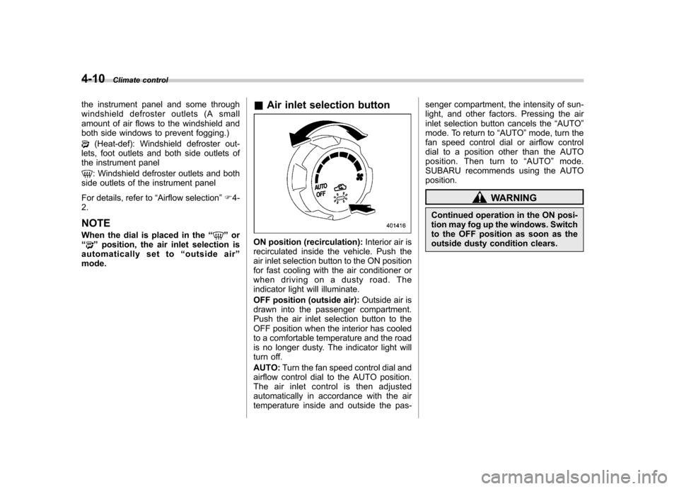
mode. &
Air inlet selection buttonON position (recirculation): Interior air is
recirculated inside the vehicle. Push the
air inlet selection button to the ON position
for fast cooling with the air conditioner or
when driving on a dusty road. The
indicator light will illuminate.
OFF position (outside air): Outside air is
drawn into the passenger compartment.
Push the air inlet selection button to the
OFF position when the interior has cooled
to a comfortable temperature and the road
is no longer dusty. The indicator light will
turn off. AUTO: Turn the fan speed control dial and
airflow control dial to the AUTO position.
The air inlet control is then adjusted
automatically in accordance with the air
temperature inside and outside the pas- senger compartment, the intensity of sun-
light, and other factors. Pressing the air
inlet selection button cancels the
“AUTO ”
mode. To return to “AUTO ”mode, turn the
fan speed control dial or airflow control
dial to a position other than the AUTO
position. Then turn to “AUTO ”mode.
SUBARU recommends using the AUTOposition.
WARNING
Continued operation in the ON posi-
tion may fog up the windows. Switch
to the OFF position as soon as the
outside dusty condition clears.
Page 177 of 416

4-12Climate control
properly and become damaged, the sys-
tem may not be able to control the interior
temperature correctly. To avoid damaging
the sensors, observe the following pre-cautions. –Do not subject the sensors to impact.
– Keep water away from the sensors.
– Do not cover the sensors.
The sensors are located as follows.– Solar sensor: beside the windshield
defroster grille.– Interior air temperature sensor: near
the ignition switch.– Outside temperature sensor: behind
the front grille. Operating tips for heater and
air conditioner &
Cleaning ventilation grille
Always keep the front ventilation inlet grille
free of snow, leaves, or other obstructions
to ensure efficient heating and defrosting.
Since the condenser is located in front of
the radiator, this area should be kept clean
because cooling performance is impaired
by any accumulation of insects and leaves
on the condenser. &Efficient cooling after parking
in direct sunlight
After parking in direct sunlight, drive with
the windows open for a few minutes to
allow outside air to circulate into the heated interior. This results in quicker
cooling by the air conditioner. Keep the
windows closed during the operation of
the air conditioner for maximum cooling
efficiency. &
Lubrication oil circulation in
the refrigerant circuit
Operate the air conditioner compressor at
a low engine speed (at idle or low driving
speeds) a few minutes each month during
the off-season to circulate its oil. & Checking air conditioning
system before summer sea-son
Check the air conditioner unit for refriger-
ant leaks, hose conditions, and proper
operation each spring. Have the air con-
ditioning system checked by your
SUBARU dealer. & Cooling and dehumidifying in
high humidity and low tem-
perature weather conditions
Under certain weather conditions (high
relative humidity, low temperatures, etc.) a
small amount of water vapor emission
from the air outlets may be noticed. This
condition is normal and does not indicate
any problem with the air conditioning
Page 244 of 416

Fuel...................................................................... 7-3
Fuel requirements ............................................... 7-3
Fuel filler lid and cap ........................................... 7-4
State emission testing (U.S. only) ...................... 7-7
Preparing to drive ............................................... 7-8
Starting the engine .............................................. 7-9
Stopping the engine ........................................... 7-10
Remote engine start system (dealer option) .............................................................. 7-10
Starting your vehicle .......................................... 7-10
Remote start safety features ............................... 7-11
Entering the vehicle while it is running via remote start ................................................................. 7-11
Entering the vehicle following remote engine start shutdown ......................................................... 7-11
Pre-heating or pre-cooling the interior of the vehicle ............................................................. 7-11
Service mode ..................................................... 7-11
Remote engine start transmitter programming and programmable feature option ..................... 7-12
System maintenance .......................................... 7-12
Manual transmission –6 speeds (STI) ............. 7-14
Selecting reverse gear ........................................ 7-15
Shifting speeds .................................................. 7-15
Driving tips ........................................................ 7-16
Manual transmission –5 speeds (except
STI) ................................................................... 7-16
Shifting speeds .................................................. 7-17
Driving tips ........................................................ 7-17
Driver ’s Control Center Differential (DCCD)
(STI) .................................................................. 7-18 To change mode of driver
’s control center
differential ....................................................... 7-18
Auto mode ........................................................ 7-19
Manual mode ..................................................... 7-20
Temporary release ............................................. 7-21
SI-DRIVE (STI) .................................................... 7-22
Intelligent (I) mode ............................................. 7-22
Sport (S) mode .................................................. 7-22
Sport Sharp (S#) mode. ...................................... 7-23
SI-DRIVE selector .............................................. 7-23
Limited slip differential (LSD) (STI) .................. 7-24
Power steering ................................................... 7-24
Braking ............................................................... 7-24
Braking tips ....................................................... 7-24
Brake system .................................................... 7-25
Disc brake pad wear warning indicators ............. 7-25
ABS (Anti-lock Brake System) .......................... 7-26
ABS system self-check ...................................... 7-26
ABS warning light .............................................. 7-26
Electronic Brake Force Distribution (EBD) system ............................................................. 7-26
Steps to take if EBD system malfunctions ..... ..... 7-27
Vehicle Dynamics Control system .................... 7-28
Vehicle Dynamics Control system monitor..... ..... 7-29
Vehicle Dynamics Control mode switch (STI) . ..... 7-29
Vehicle Dynamics Control OFF switch (except STI) ................................................................. 7-30
Tire pressure monitoring system (TPMS) (U.S.-spec. models). ........................................ 7-32
Parking your vehicle ......................................... 7-33
Starting and operating
7
Page 254 of 416

an additional four times. If the vehicle fails
to start after the additional attempts, the
remote engine start system will abort and
return to a non-activated state. &Remote start safety features
For safety and security reasons, the
system will fail to start and beep the horn
twice or shut down the engine during
remote start operation if any of the
following conditions occur. . The brake pedal is depressed before
the vehicle ignition switch is turned “on ”.
. The key was already in the ignition
switch.. The engine hood is opened.
. The vehicle ’s engine idle speed has
reached a level over 3,000 rpm.. The alarm is triggered by opening a
door or the rear gate.
NOTE . The security indicator light on the
combination meter will stop flashing
while under remote engine start opera-
tion, but the vehicle is still protected.. If the vehicle is entered during
remote engine start operation, the
system will not record entry in the
alarm history. &
Entering the vehicle while it
is running via remote start
1. Unlock the vehicle doors using the
remote keyless entry system. If the vehi-cle ’s doors are unlocked manually using
the key, the vehicle ’s alarm system will
trigger and the remote engine start system
will turn off. Inserting the key into the
ignition switch and turning it to the “ON ”
position or pressing the unlock button “
”
on the remote keyless entry transmitter
will disarm the alarm system. Refer to“ Alarm system ”F 2-15.
2. Enter the vehicle. Do not depress the
brake pedal.
3. Insert the key into the ignition switch
and turn to the “ON ”position. If the ignition
switch is accidentally turned to the“ START ”position, the system ’s “starter
anti-grind ”feature will prevent the starter
from re-cranking.
4. Depress the brake pedal. The remote
starter disengages, the vehicle ’s power
window features are re-enabled and the
vehicle will operate normally.
& Entering the vehicle follow-
ing remote engine start shut-down
An alarm trigger may occur if the vehicle is
opened by the remote keyless entry transmitter within a few seconds immedi-
ately following remote engine start shut-down. &
Pre-heating or pre-cooling
the interior of the vehicle
Before exiting the vehicle, set the tem-
perature controls to the desired setting
and operation. After the system starts the
vehicle, the heater or air-conditioning will
activate and heat or cool the interior to
your setting. & Service mode
In service mode, the remote start function
is temporarily disabled to prevent the
system from unexpectedly starting the
engine while being serviced. ! To engage the service mode
Turntheignitionswitchtothe “ON ”
position, depress and hold the brake
pedal, then press and release the “
”
button on the remote engine start trans-
mitter three times. The system will pause
for 1 second and then flash the turn signal
lights and honk the horn three times
indicating that the system is in service
mode. When attempting to activate the
remote start system while in service
mode, the turn signal lights will flash and
the horn will honk two times and will not Starting and operating
7-11
– CONTINUED –