2012 SUBARU IMPREZA WRX window
[x] Cancel search: windowPage 172 of 416

inletselectionbuttonintheON
position may fog up the windows.
Switch to the OFF position as soon
as the outside dusty conditionclears.
& Air conditioner operation
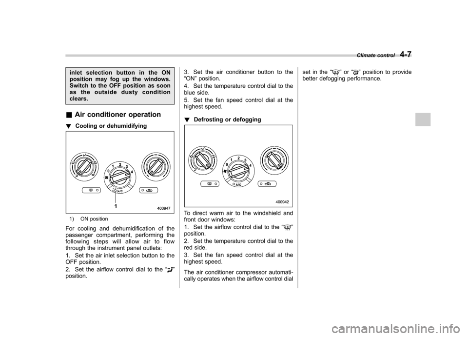
! Cooling or dehumidifying
1) ON position
For cooling and dehumidification of the
passenger compartment, performing the
following steps will allow air to flow
through the instrument panel outlets:
1. Set the air inlet selection button to the
OFF position.
2. Set the airflow control dial to the “
”
position. 3. Set the air conditioner button to the “
ON ”position.
4. Set the temperature control dial to the
blue side.
5. Set the fan speed control dial at the
highest speed. ! Defrosting or defogging
To direct warm air to the windshield and
front door windows:
1. Set the airflow control dial to the “
”
position.
2. Set the temperature control dial to the
red side.
3. Set the fan speed control dial at the
highest speed.
The air conditioner compressor automati-
cally operates when the airflow control dial set in the
“
”or “”position to provide
better defogging performance. Climate control
4-7
Page 175 of 416

4-10Climate control
the instrument panel and some through
windshield defroster outlets (A small
amount of air flows to the windshield and
both side windows to prevent fogging.)
(Heat-def): Windshield defroster out-
lets, foot outlets and both side outlets of
the instrument panel
: Windshield defroster outlets and both
side outlets of the instrument panel
For details, refer to “Airflow selection ”F 4-
2. NOTE
When the dial is placed in the “
”or
“” position, the air inlet selection is
automatically set to “outside air ”
mode. &
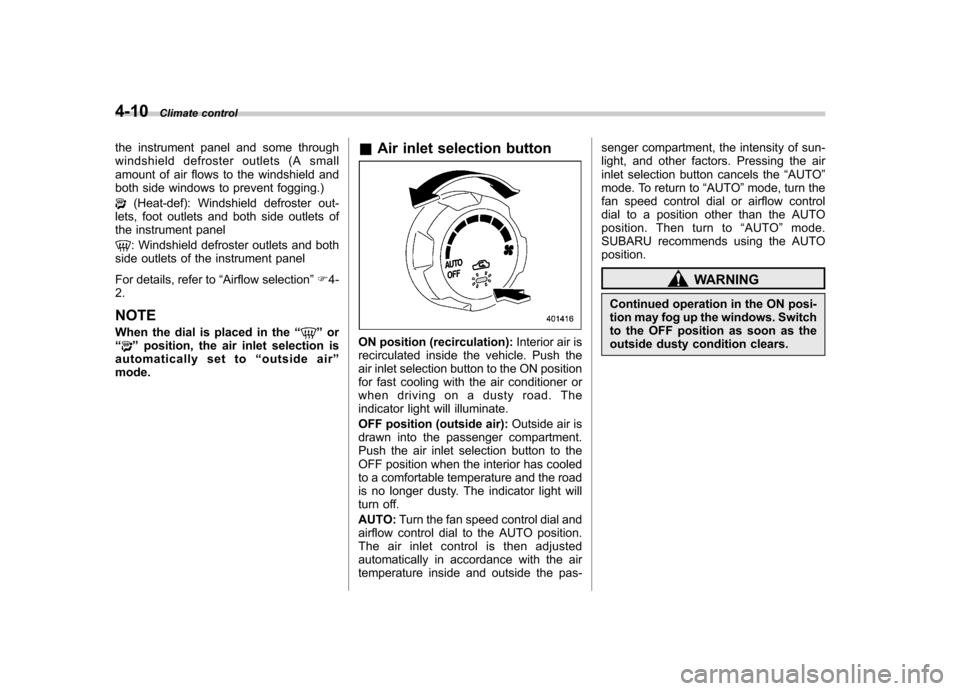
Air inlet selection buttonON position (recirculation): Interior air is
recirculated inside the vehicle. Push the
air inlet selection button to the ON position
for fast cooling with the air conditioner or
when driving on a dusty road. The
indicator light will illuminate.
OFF position (outside air): Outside air is
drawn into the passenger compartment.
Push the air inlet selection button to the
OFF position when the interior has cooled
to a comfortable temperature and the road
is no longer dusty. The indicator light will
turn off. AUTO: Turn the fan speed control dial and
airflow control dial to the AUTO position.
The air inlet control is then adjusted
automatically in accordance with the air
temperature inside and outside the pas- senger compartment, the intensity of sun-
light, and other factors. Pressing the air
inlet selection button cancels the
“AUTO ”
mode. To return to “AUTO ”mode, turn the
fan speed control dial or airflow control
dial to a position other than the AUTO
position. Then turn to “AUTO ”mode.
SUBARU recommends using the AUTOposition.
WARNING
Continued operation in the ON posi-
tion may fog up the windows. Switch
to the OFF position as soon as the
outside dusty condition clears.
Page 177 of 416

4-12Climate control
properly and become damaged, the sys-
tem may not be able to control the interior
temperature correctly. To avoid damaging
the sensors, observe the following pre-cautions. –Do not subject the sensors to impact.
– Keep water away from the sensors.
– Do not cover the sensors.
The sensors are located as follows.– Solar sensor: beside the windshield
defroster grille.– Interior air temperature sensor: near
the ignition switch.– Outside temperature sensor: behind
the front grille. Operating tips for heater and
air conditioner &
Cleaning ventilation grille
Always keep the front ventilation inlet grille
free of snow, leaves, or other obstructions
to ensure efficient heating and defrosting.
Since the condenser is located in front of
the radiator, this area should be kept clean
because cooling performance is impaired
by any accumulation of insects and leaves
on the condenser. &Efficient cooling after parking
in direct sunlight
After parking in direct sunlight, drive with
the windows open for a few minutes to
allow outside air to circulate into the heated interior. This results in quicker
cooling by the air conditioner. Keep the
windows closed during the operation of
the air conditioner for maximum cooling
efficiency. &
Lubrication oil circulation in
the refrigerant circuit
Operate the air conditioner compressor at
a low engine speed (at idle or low driving
speeds) a few minutes each month during
the off-season to circulate its oil. & Checking air conditioning
system before summer sea-son
Check the air conditioner unit for refriger-
ant leaks, hose conditions, and proper
operation each spring. Have the air con-
ditioning system checked by your
SUBARU dealer. & Cooling and dehumidifying in
high humidity and low tem-
perature weather conditions
Under certain weather conditions (high
relative humidity, low temperatures, etc.) a
small amount of water vapor emission
from the air outlets may be noticed. This
condition is normal and does not indicate
any problem with the air conditioning
Page 198 of 416

&Play file
NOTE . Copyright protected MP3/WMA/AAC
files will not be played by the system.
The player will automatically skip to the
next file (track).. WMA9 Lossless, WMA9 Profes-
sional and WMA9 voice cannot beplayed. MP3: . Based on MPEG1, 2 and 2.5 Layer3
. Sampling rate (kHz): 48, 44.1, 32, 24,
22.05, 16, 12, 11.025, 8. Bit rate (kbps): 8 to 320
. Supports variable bit rates
WMA:. Based on Windows Media Audio 9
. Bit rate (kbps): 32 to 192
AAC (type B audio):. Based on MPEG4 AAC (ISO/IEC
14496-12: 2003+iTune Meta-data Specifi- cation) . Sampling rate (kHz): 48, 44.1, 32, 24,
22.05, 16, 12, 11.025, 8. Bit rate (kbps): 8 to 320
. Number of channels: 1 to 2ch &
How to insert a CD(s) (type A)
1. Briefly press the
button. If the
magazine in the player has a spare slot
where you can insert a disc, the disc
number indicator associated with the
spare slot will blink.
If no indicator blinks, it means that there
are no spare slots in the magazine.
2. When the “LOAD ”indicator illumi-
nates, insert the disc. Once you have
inserted the disc, the “LOAD ”indicator will
turn off. The disc will then be automatically
drawn in, and the player will begin to play
back the first track of the disc. . To insert more discs in succession,
repeat steps 1 and 2. The magazine will
be loaded with discs in the ascending
order of slot number.
If you do not insert any disc within 15
seconds after you have pressed the
button, the player will begin to play back
the first track of the last disc you haveinserted. . The disc indicator lights up continu-
ously if a disc is already inserted in the
corresponding position of the magazine. . While the player is in the loading mode,
if you press
orbutton, the
player will enter the standby mode. Press the
button to start playback. !
Inserting a disc in a desired posi- tion
1. Briefly press the
button. If the
magazine in the player has a spare slot
where you can insert a disc, the disc
number indicator associated with the
spare slot will blink.
The slots in the magazine the indicator of
which steadily lights up are already loaded
with discs.
2. Press the disc select button (from
to) at the slot where you want
to insert a disc.
3. When the “LOAD ”indicator illumi-
nates, insert the disc. Once you have
inserted the disc, the “LOAD ”indicator will
turn off. The disc will then be automatically
drawn in, and the player will begin to play
the first track on the disc. . If you wish to insert another disc,
repeat the procedure beginning with step 1.
If you do not insert any disc within 15
seconds after you have pressed the
button, the player will begin to play back
the first track of the last disc you haveinserted. . While the player is in the loading mode,
if you press
orbutton, the
player will enter the standby mode. Press the
button to start playback. Audio
5-17
– CONTINUED –
Page 217 of 416

5-36Audio
.When the ignition switch is turned to
the “LOCK ”position during a call, the
call may be disconnected or continued
on the cell phone depending on the
type of cell phone that is used. Note
that operation of the cell phone may be
necessary if the call is continued on the
cell phone. . Do not speak at the same time as the
other party during a call. If you and the
party speak at the same time, it may be
difficult for the other party to hear your
voice and vice versa. This is normal. . The receiver sound volume should
be set as low as possible. Otherwise,
the party you are calling may notice an
undesirable echo sound. . Speak clearly and loudly.
. Your voice may be difficult to be
heard by the party under the following conditions.
–Driving on a rough road.
– Driving at a high speed.
– Driving with a window open.
– When air from the ventilator
blows directly towards the micro-phone. – When the sound coming from the
ventilator is loud.– When the cell phone is too close
to the microphone. .
The sound quality may degrade due
to the influence of the cell phone that is
connected to the system or the circum-
stances of the Bluetooth network. . When another Bluetooth
®device is
simultaneously connected, noise may
be heard in the voice coming from the
hands-free phone. ! Corresponding profiles for the cell phone
. HFP (Hands Free Profile): Ver. 1.0
. OPP (Object Push Profile): Ver. 1.1
& Certification for the Hands-
free system
CAUTION
FCC WARNING
Changes or modifications not ex-
pressly approved by the party re-
sponsible for compliance could void
the user ’s authority to operate the
equipment.
NOTE
This device complies with Part 15 of
the FCC Rules and RSS-Gen of IC
Rules. Operation is subject to the
following two conditions: (1) this de- vice may not cause harmful interfer-
ence, and (2) this device must accept
any interference received, including
interference that may cause undesiredoperation. NOTE
This equipment has been tested and
found to comply with the limits for a
Class B digital device, pursuant to Part
15 of the FCC Rules. These limits are
designed to provide reasonable protec-
tion against harmful interference in a
residential installation. This equipment
may cause harmful interference to
radio communications, if it is not
installed and used in accordance with
the instructions. However, there is no
guarantee that interference will not
occur in a particular installation. If this
equipment does cause harmful inter-
ference to radio or television reception,
which can be determined by turning the
equipment off and on, the user is
encouraged to try to correct the inter-
ference by one or more of the followingmeasures. .
Reorient or relocate the receiving
antenna. . Increase the separation between the
equipment and receiver.. Connect the equipment into an out-
Page 233 of 416

6-4Interior equipment
Sun visors
To block out glare, swing down the visors.
To use the sun visor at a side window,
swing it down and move it sideways. &
Vanity mirror
CAUTION
Keep the vanity mirror cover closed
while the car is being driven to avoid
being temporarily blinded by the
glare of bright light.
To use the vanity mirror, swing down the
sun visor and open the vanity mirror cover. Storage compartment
CAUTION
. Always keep the storage com-
partment closed while driving to
reduce the risk of injury in the
event of a sudden stop or anaccident.
. Do not store spray cans, contain-
ers with flammable or corrosive
liquids or any other dangerous
items in the storage compart-ment.
Page 248 of 416

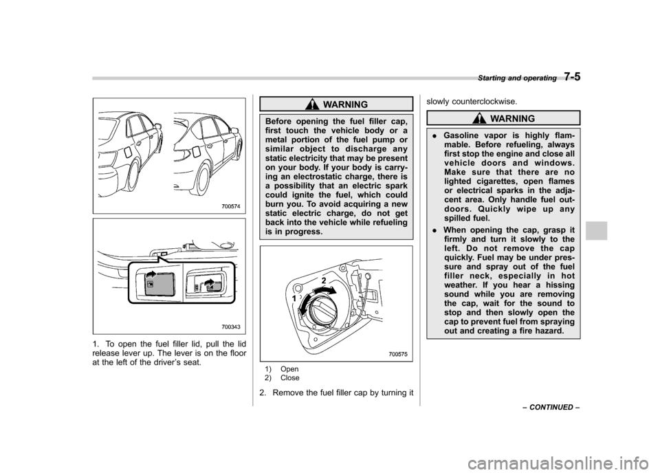
1. To open the fuel filler lid, pull the lid
release lever up. The lever is on the floor
at the left of the driver’s seat.
WARNING
Before opening the fuel filler cap,
first touch the vehicle body or a
metal portion of the fuel pump or
similar object to discharge any
static electricity that may be present
on your body. If your body is carry-
ing an electrostatic charge, there is
a possibility that an electric spark
could ignite the fuel, which could
burn you. To avoid acquiring a new
static electric charge, do not get
back into the vehicle while refueling
is in progress.
1) Open
2) Close
2. Remove the fuel filler cap by turning it slowly counterclockwise.
WARNING
. Gasoline vapor is highly flam-
mable. Before refueling, always
first stop the engine and close all
vehicle doors and windows.
Make sure that there are no
lighted cigarettes, open flames
or electrical sparks in the adja-
cent area. Only handle fuel out-
doors. Quickly wipe up any
spilled fuel.
. When opening the cap, grasp it
firmly and turn it slowly to the
left. Do not remove the cap
quickly. Fuel may be under pres-
sure and spray out of the fuel
filler neck, especially in hot
weather. If you hear a hissing
sound while you are removing
the cap, wait for the sound to
stop and then slowly open the
cap to prevent fuel from spraying
out and creating a fire hazard. Starting and operating
7-5
– CONTINUED –
Page 251 of 416

7-8Starting and operating
.A vehiclefails the OBDII inspection if
the “CHECK ENGINE ”warning light is not
properly operating (light is illuminated or is
not working due to a burned out bulb) or
there is one or more diagnostic trouble
codes stored in the vehicle ’s computer.
. A state emission inspection may reject
(not pass or fail) a vehicle if the number of
OBDII system readiness monitors “NOT
READY ”is greater than one. If the
vehicle ’s battery has been recently re-
placed or disconnected, the OBDII system
inspection may indicate that the vehicle is
not ready for the emission test. Under this
condition, the vehicle driver should be
instructed to drive his/her vehicle for a few
days to reset the readiness monitors and
return for an emission re-inspection. . Owners of rejected or failing vehicles
should contact their SUBARU Dealer for service.
Some states still use dynamometers in
their emission inspection program. A
dynamometer is a treadmill or roller-like
testing device that allows your vehicle ’s
wheels to turn while the vehicle remains in
one place. Prior to your vehicle being put
on a dynamometer, tell your emission
inspector
not to place your SUBARU
AWD vehicle on a two-wheel dynam-
ometer. Otherwise, serious transmis-
sion damage will result. The U.S. Environmental Protection
Agency (EPA) and states using two-wheel
dynamometers in their emission testing
program have EXEMPTED SUBARU
AWD vehicles from the portion of the
testing program that involves a two-wheel
dynamometer. There are some states that
use four-wheel dynamometers in their
testing program. When properly used, this
equipment should not damage a SUBARU
AWD vehicle.
Under no circumstances should the rear
wheels be jacked off the ground, nor
should the driveshaft be disconnected for
state emission testing.
Preparing to drive
You should perform the following checks
and adjustments every day before you
start driving.
1. Check that all windows, mirrors, and
lights are clean and unobstructed.
2. Check the appearance and condition
of the tires. Also check tires for properinflation.
3. Look under the vehicle for any sign of leaks.
4. Check that the hood, trunk (4-door)
and rear gate (5-door) are fully closed.
5. Check the adjustment of the seat.
6. Check the adjustment of the inside
and outside mirrors.
7. Fasten your seatbelt. Check that your
passengers have fastened their seatbelts.
8. Check the operation of the warning
and indicator lights when the ignition
switch is turned to the
“ON ”position.
9. Check the gauges, indicator and warn-
ing lights after starting the engine.
NOTE
Engine oil, engine coolant, brake fluid,
washer fluid and other fluid levels
should be checked daily, weekly or at
fuel stops.