2012 SUBARU IMPREZA WRX lights
[x] Cancel search: lightsPage 307 of 416
9-10In case of emergency
eye protectors, and remove metal
objects such as rings, bands or
other metal jewelry.
. Be sure the jumper cables and
clamps on them do not have
loose or missing insulation.
Do not jump start unless cables
in suitable condition are avail-able.
. A running engine can be danger-
ous. Keep your fingers, hands,
clothing, hair and tools away
from the cooling fan, belts and
any other moving engine parts.
Removing rings, watches and
ties is advisable.
. Jump starting is dangerous if it
done incorrectly. If you are un-
sure about the proper procedure
for jump starting, consult a com-
petent mechanic.
When your vehicle does not start due to a
run down (discharged) battery, the vehicle
may be jump started by connecting your
battery to another battery (called the
booster battery) with jumper cables. &
How to jump start
1. Make sure the booster battery is 12
volts and the negative terminal isgrounded.
2. If the booster battery is in another
vehicle, do not let the two vehicles touch.
3. Turn off all unnecessary lights and accessories.
4. Connect the jumper cables exactly in
the sequence illustrated.
Page 323 of 416
Maintenance and serviceTire replacement .............................................. 11-29
Wheel replacement ........................................... 11-30
Aluminum wheels ............................................. 11-30
Windshield washer fluid .................................. 11-31
Replacement of wiper blades .......................... 11-32
Windshield wiper blade assembly ..................... 11-33
Windshield wiper blade rubber (type A and type B) .................................................................. 11-33
Rear window wiper blade assembly (5-door models). ......................................................... 11-34
Rear window wiper blade rubber (5-door models). ......................................................... 11-35
Battery. .............................................................. 11-36
Fuses ................................................................ 11-37 Installation of accessories
.............................. 11-39
Replacing bulbs ............................................... 11-39
Headlights (models with HID headlights) ........... 11-39
Headlights (models without HID headlights) ...... 11-39
Front turn signal light ...................................... 11-42
Front fog light (if equipped) .............................. 11-42
Rear combination lights ................................... 11-43
Back-up light (5-door) ...................................... 11-45
License plate light ........................................... 11-45
Map light ......................................................... 11-46
Dome light and cargo area light ....................... 11-47
Trunk light ....................................................... 11-47
High mount stop light (4-door) (except LED [Light Emitting Diode] type) ............................ 11-47
Other bulbs ..................................................... 11-47
Page 359 of 416
11-38Maintenance and service
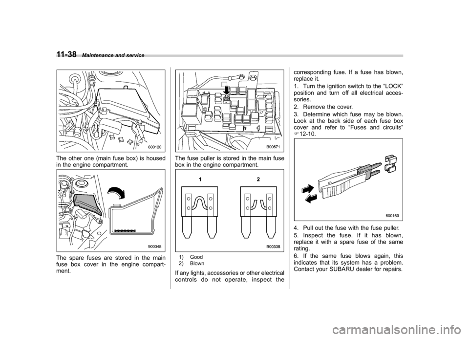
The other one (main fuse box) is housed
in the engine compartment.
The spare fuses are stored in the main
fuse box cover in the engine compart-ment.
The fuse puller is stored in the main fuse
box in the engine compartment.
1) Good
2) Blown
If any lights, accessories or other electrical
controls do not operate, inspect the corresponding fuse. If a fuse has blown,
replace it.
1. Turn the ignition switch to the
“LOCK ”
position and turn off all electrical acces- sories.
2. Remove the cover.
3. Determine which fuse may be blown.
Look at the back side of each fuse box
cover and refer to “Fuses and circuits ”
F 12-10.
4. Pull out the fuse with the fuse puller.
5. Inspect the fuse. If it has blown,
replace it with a spare fuse of the samerating.
6. If the same fuse blows again, this
indicates that its system has a problem.
Contact your SUBARU dealer for repairs.
Page 360 of 416
Installation of accessories
Always consult your SUBARU dealer
before installing fog lights or any other
electrical equipment in your vehicle. Such
accessories may cause the electronic
system to malfunction if they are incor-
rectly installed or if they are not suited for
the vehicle.Replacing bulbs
WARNING
Bulbs may become very hot while
illuminated. Before replacing bulbs,
turn off the lights and wait until the
bulbs cool down. Otherwise, there is
a risk of sustaining a burn injury.
CAUTION
Replace any bulb only with a new
bulb of the specified wattage. Using
a bulb of different wattage could
result in a fire. For the specified
wattage of each bulb, refer to “Bulb
chart ”F 12-14.
& Headlights (models with HID headlights)
WARNING
High-intensity-discharge (HID) bulbs
are used for the low beams of the
headlights. These HID bulbs use an
extremely high voltage. To avoid the
risk of an electric shock that could
result in serious injury, observe the following precautions. .
Do not replace any headlight
bulbs (both low beam and high
beam) by yourself.
. Do not remove/restore the head-
light assemblies by yourself.
. Do not remove any headlight-
assembly components by your-self.
For replacement, contact your
SUBARU dealer.
& Headlights (models without
HID headlights)
CAUTION
Halogen headlight bulbs become
very hot while in use. If you touch
the bulb surface with bare hands or
greasy gloves, fingerprints or
grease on the bulb surface will
develop into hot spots, causing the
bulb to break. If there are finger
prints or grease on the bulb surface,
wipe them away with a soft cloth
moistened with alcohol. Maintenance and service
11-39
– CONTINUED –
Page 364 of 416
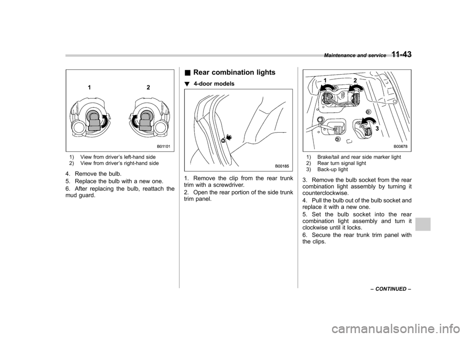
1) View from driver’s left-hand side
2) View from driver ’s right-hand side
4. Remove the bulb.
5. Replace the bulb with a new one.
6. After replacing the bulb, reattach the
mud guard. &
Rear combination lights
! 4-door models
1. Remove the clip from the rear trunk
trim with a screwdriver.
2. Open the rear portion of the side trunk
trim panel.
1) Brake/tail and rear side marker light
2) Rear turn signal light
3) Back-up light
3. Remove the bulb socket from the rear
combination light assembly by turning itcounterclockwise.
4. Pull the bulb out of the bulb socket and
replace it with a new one.
5. Set the bulb socket into the rear
combination light assembly and turn it
clockwise until it locks.
6. Secure the rear trunk trim panel with
the clips. Maintenance and service
11-43
– CONTINUED –
Page 383 of 416
12-14Specifications
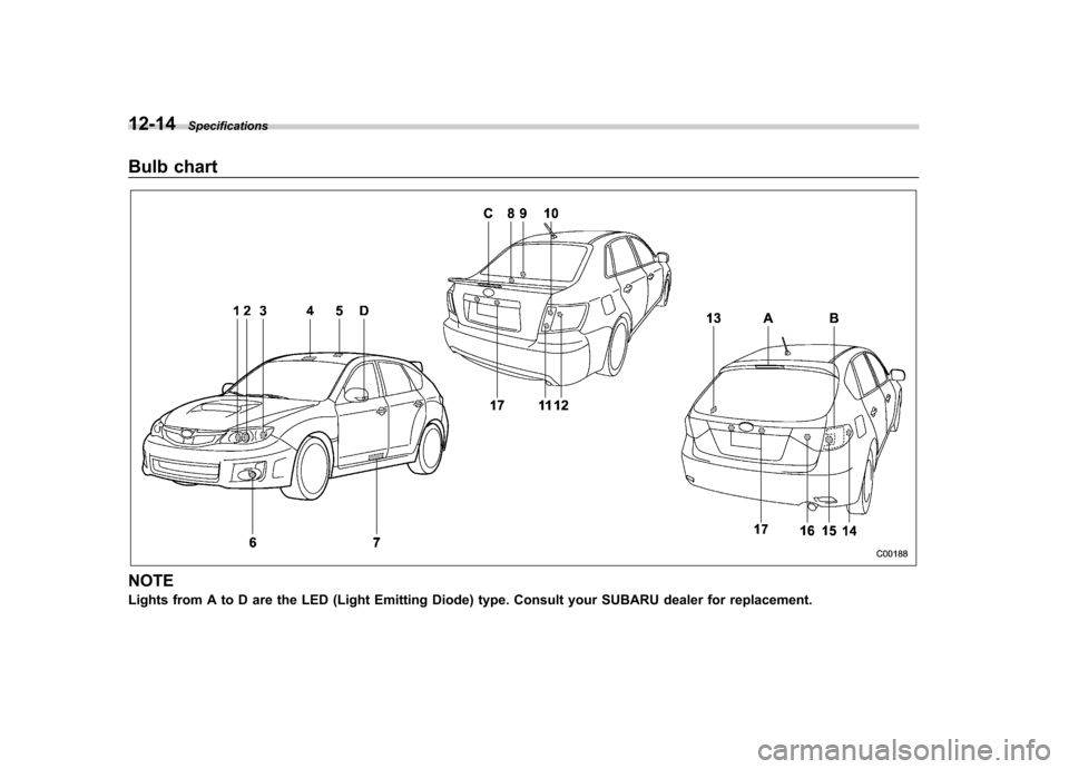
Bulb chart
NOTE
Lights from A to D are the LED (Light Emitting Diode) type. Consult your SUBARU dealer for replacement.
Page 384 of 416
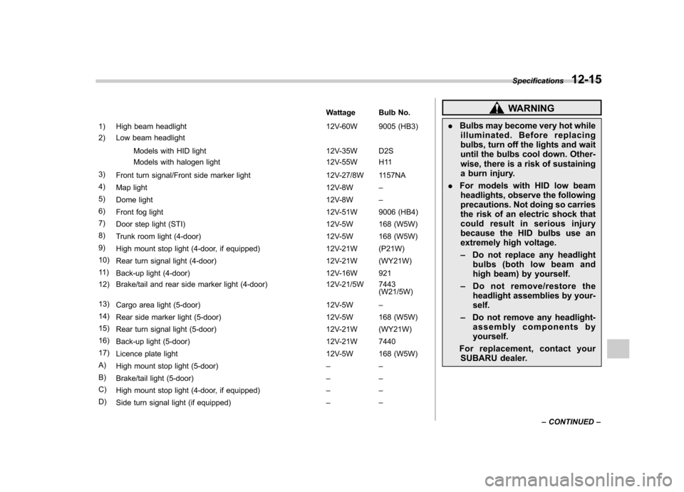
Wattage Bulb No.
1) High beam headlight 12V-60W 9005 (HB3)
2) Low beam headlight
Models with HID light 12V-35W D2S
Models with halogen light 12V-55W H11
3) Front turn signal/Front side marker light 12V-27/8W 1157NA
4) Map light 12V-8W–
5) Dome light 12V-8W–
6) Front fog light 12V-51W 9006 (HB4)
7) Door step light (STI) 12V-5W 168 (W5W)
8) Trunk room light (4-door) 12V-5W 168 (W5W)
9) High mount stop light (4-door, if equipped) 12V-21W (P21W)
10) Rear turn signal light (4-door) 12V-21W (WY21W)
11 ) Back-up light (4-door) 12V-16W 921
12) Brake/tail and rear side marker light (4-door) 12V-21/5W 7443 (W21/5W)
13) Cargo area light (5-door) 12V-5W–
14) Rear side marker light (5-door) 12V-5W 168 (W5W)
15) Rear turn signal light (5-door) 12V-21W (WY21W)
16) Back-up light (5-door) 12V-21W 7440
17) Licence plate light 12V-5W 168 (W5W)
A) High mount stop light (5-door) ––
B) Brake/tail light (5-door) ––
C) High mount stop light (4-door, if equipped) ––
D) Side turn signal light (if equipped) ––WARNING
. Bulbs may become very hot while
illuminated. Before replacing
bulbs, turn off the lights and wait
until the bulbs cool down. Other-
wise, there is a risk of sustaining
a burn injury.
. For models with HID low beam
headlights, observe the following
precautions. Not doing so carries
the risk of an electric shock that
could result in serious injury
because the HID bulbs use an
extremely high voltage. – Do not replace any headlight
bulbs (both low beam and
high beam) by yourself.
– Do not remove/restore the
headlight assemblies by your-self.
– Do not remove any headlight-
assembly components byyourself.
For replacement, contact your SUBARU dealer. Specifications
12-15
– CONTINUED –
Page 409 of 416
14-6Index
I
Ignition switch .............................................................. 3-3
Light ....................................................................... 3-4
Illumination brightness control ...................................... 3-31
Immobilizer. ................................................................. 2-2
Indicator light (security indicator light) ....................... 3-23
Indicator light Cruise control ........................................................ 3-24
Cruise control set ................................................... 3-24
Front fog light ........................................................ 3-24
Headlight .............................................................. 3-24
High beam ............................................................ 3-24
Hill start assist OFF ................................................ 3-20
Immobilizer. ........................................................... 3-23
REV ..................................................................... 3-25Security ................................................................ 3-23
Shift-up ................................................................. 3-23
SI-DRIVE .............................................................. 3-23
Traction control OFF ............................................... 3-21
Turn signal ............................................................ 3-24
Vehicle Dynamics Control OFF ................................ 3-21
Vehicle Dynamics Control operation ................. 3-20, 3-21
Information display ..................................................... 3-26
Inside mirror .............................................................. 3-37
Interior lights ............................................................... 6-2
Internal trunk lid release handle ................................... 2-24
iiPod
®operations ........................................................ 5-26 J
Jack and jack handle
................................................... 9-4
Jack-up point .............................................................. 9-5
Jump starting .............................................................. 9-9
K
Key............................................................................ 2-2 Number .................................................................. 2-2
Reminder chime ...................................................... 3-4
Replacement. .......................................................... 2-3
L
Leather seat materials ................................................. 10-5
License plate light ..................................................... 11-45
Light
Back-up (4-door) .................................................. 11-43
Back-up (5-door) .................................................. 11-45
Brake/Tail and rear side marker (4-door) .................. 11-43
Cargo area ............................................................. 6-2
Control switch ........................................................ 3-29
Dome ..................................................................... 6-2
Front fog ..................................................... 3-33, 11-42
Front position ......................................................... 3-29
High mount stop ................................................... 11-47
Ignition switch ......................................................... 3-4
License plate ....................................................... 11-45
Map .............................................................. 6-3, 11-46
Rear combination ................................................. 11-43
Trunk .................................................................. 11-47
Turn signal ........................................ 3-30, 11-42, 11-43
Limited slip differential (LSD). ....................................... 7-24